
HP StorageWorks B-Series Multi-protocol Router Blade Installation Guide (A7990-90002, June 2006)


B-Series Multi-protocol Router blade installation guide 23
3 Operating the B-Series MP Router blade
This chapter provides the following information:
• Interpreting LED activity, page 23 next
• Interpreting POST results, page 26
• Maintaining the B-Series MP Router blade, page 26
• Powering the B-Series MP Router blade on and off, page 27
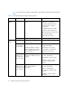
Interpreting LED activity
System activity and status can be determined through the activity of the LEDs on the switch.
There are three possible LED states:
• no light
• steady light
• flashing light
The lights are in one of the following colors:
• Green
• Amber
The status LEDs may display amber or flash during boot, POST, or other diagnostic tests. This is
normal; it does not indicate a problem unless the LEDs do not indicate a healthy state after all boot
processes and diagnostic tests are complete.
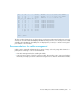
LEDs on the B-Series MP Router blade
The B-Series MP Router blade has the following LEDs:
• One system status LED (top right)
• One power status LED (top left)
• 16 FC port LEDs
• 2 GbE port LEDs
NOTE: The pairs of port LEDs for all 18 ports are arrayed to the left of the row of ports. The pairs
of port LEDs are located in the array in the same relative positions as the ports.