HP Storage SAN Visibility 6.0 User Guide Abstract This document describes how to use the HP Storage SAN Visibility user interface to review the topology and inventory in a complex Storage Area Network (SAN) environment. This document is intended for users and HP authorized service providers who use the HP Storage SAN Visibility software to obtain SAN analysis reports.
© Copyright 2006, 2013 Hewlett-Packard Development Company, L.P. Confidential computer software. Valid license from HP required for possession, use or copying. Consistent with FAR 12.211 and 12.212, Commercial Computer Software, Computer Software Documentation, and Technical Data for Commercial Items are licensed to the U.S. Government under vendor's standard commercial license. The information contained herein is subject to change without notice.
Contents 1 Overview..................................................................................................6 HP Storage SAN Visibility package contents................................................................................7 Hardware and software requirements..........................................................................................7 2 Install, repair, and remove SAN Visibility.......................................................9 Supported Operating Systems..............
Viewing raw data.........................................................................................................41 Determining the SMTP server IP address...........................................................................42 Viewing reports.................................................................................................................43 Comparing SAN................................................................................................................
Figures 1 2 3 4 5 6 7 8 9 10 11 12 13 14 15 16 17 18 19 20 21 22 23 24 25 26 27 28 29 30 31 WMI Mapper dialog box.................................................................................................10 SAN Visibility welcome screen...........................................................................................12 SAN Visibility GUI...........................................................................................................13 SAN Settings window............................
1 Overview HP Storage SAN Visibility provides a quick and easy way to review the topology and inventory in a complex Storage Area Network (SAN) environment. HP Storage SAN Visibility offers the following features: • Provides an intuitive, simple, and easy to use graphical user interface (GUI). • Collects SAN information, such as Fibre Channel (FC) switch details, host details, Host Bus Adaptor (HBA) details, and Storage Array Connectivity information, by logging in to the FC switches and the hosts.
This chapter addresses the following topics: • “HP Storage SAN Visibility package contents” (page 7) • “Hardware and software requirements” (page 7) HP Storage SAN Visibility package contents Following are the components of the HP Storage SAN Visibility bundle: • HP Storage SAN Visibility installer (SANVisibility_Setup.exe) • Product documentation • Licenses Hardware and software requirements This section discusses the hardware and software requirements for installing HP Storage SAN Visibility.
Table 1 Hardware requirements Minimum Recommended Pentium III processor 128 MB RAM 10 Base-T Ethernet port Pentium IV processor 256 MB RAM 100 Base-T Ethernet port Standard LAN connectivity with target FC switches and hosts 8 Overview
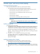
2 Install, repair, and remove SAN Visibility Supported Operating Systems Following are the prerequisites to install and run HP Storage SAN Visibility: • Microsoft Windows system with any of the following operating systems: ◦ Microsoft Windows Server 2003 Standard or Enterprise edition with Service Pack 2 ◦ Microsoft Windows XP Professional edition with Service Pack 2 ◦ Microsoft Windows Server 2008 Enterprise Edition with Service Pack 2 ◦ Microsoft Windows 7 ◦ Microsoft Windows 2008 R2 ◦ Micros
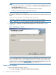
NOTE: 4. • To Upgrade to SAN Visibility , select Next in the Welcome to the InstallShield of the HP Storage SAN Visibility dialog box. • SAN Visibility user must be installed with the administrator privileges. • Installing SAN Visibility installs WMI mapper internally. Review and accept the license agreement.
2. 3. Select HP Storage SAN Visibility from the list of Currently Installed Programs. Click Change, and select Repair and follow the steps to repair the program. NOTE: WMI Mapper cannot be repaired from Add/Remove programs directly . At the time of repairing SAN Visibility, WMI Mapper is also repaired internally. Removing SAN Visibility To remove the HP Storage SAN Visibility software, complete the following steps: 1. Select Start > Settings > Control Panel > Add or Remove Programs. 2.
3 Using SAN Visibility This chapter addresses the following topics: • “SAN Visibility GUI” (page 12) • “Using SAN Visibility” (page 14) Following is a brief overview of using HP Storage SAN Visibility: 1. Specify the SAN details. 2. Specify the switch details. 3. Specify the host details. 4. Specify your contact information. 5. Run data collection. 6. Email the data collected (with .hp extension) to HP at: “SAN_Visibility@hp.com” for analysis.
• C — SAN explorer area • D — Message area • E — up and down arrow button available in the message area to expand it for a better view of the messages Figure 3 SAN Visibility GUI SAN Visibility menus Table 2 (page 13) lists the SAN Visibility menu items. Table 2 SAN Visibility file menus Menu: To... Select...
Table 2 SAN Visibility file menus (continued) Menu: To... Select... Access SAN Visibility home page Help > SAN Visibility On Web Enable Migration Recommendation Help > HP Support Engineer Settings View the welcome screen Help > Welcome Screen Access information about SAN Visibility Help > About SAN Visibility Send the logs Help > Send Logs > Select one of the following options: • Place on Desktop: Places the log file on the desktop.
Specifying SAN details The SAN Settings window displays SAN details. It enables you to add and modify a SAN group. Figure 4 (page 15) shows the SAN Settings window. Figure 4 SAN Settings window Adding SAN details To add SAN details: 1. Click SAN Settings from the navigation area. The SAN Settings window is displayed in the main display area. The default SAN name, MySAN, is displayed in the SAN Name box, as shown in Figure 4 (page 15).
To enter the Component Group Name: 1. Enter the name of your component group in the Component Group Name box. The default component group name, MyComponentGroup, is displayed in the Component Group Name box, as shown in Figure 4 (page 15). 2. Click Add. The component group name appears in the SAN explorer area under the SAN name. NOTE: 3. To add multiple component groups under the SAN, repeat the steps 1-2. Click Rename, to rename the existing Component Group name accordingly: 1.
Adding a switch To add a switch: 1. Click Switch Settings from the navigation area. The Switch Settings window is displayed in the main display area. 2. Select one of the following options from the main display area: • IP Address: If you know the IP address of the switch to scan. a. Enter the IP address of the switch to be scanned in the IP Address box, as shown in Figure 5 (page 16). b. Select Discover connected switches check box if you want to discover all the connected switches. c.
Figure 6 Brocade AG mode switch example Modifying switch details To modify switch details: 1. Select the switch you want to modify from the SAN explorer area to view its details. 2. Modify the switch details as required. 3. Click Update to save the modified switch details. Removing a switch To remove a switch from the component group: 1. Select the switch you want to remove from the SAN explorer area. 2. Right-click and select Remove from the pop-up menu, as shown in Figure 7 (page 18). 3.
Removing a component group To remove a component group from the SAN: 1. Select the component group that you want to remove from the SAN explorer area. 2. Right-click and select Remove from the pop-up menu, as shown in Figure 8 (page 19). 3. The Delete Confirmation window is displayed with the following message: Do you want to delete the XYZComponentGroup? • Click Yes, to delete the ComponentGroup. • Click No to cancel the deletion. The component group is removed from the SAN.
4. Click Rename. The component group is renamed. Figure 9 Renaming component group Clear All a component group You can use the Clear all option is used to collapse the components under the respective Component Group. 1. Select the component group that you want to collapse. 2. Right-click and select Clear All from the pop-up menu, as shown in Figure 10: Clear All component group.
Figure 10 Clear All component group Specifying host details The Host Settings window enables you to discover and add hosts in a SAN environment. Figure 11 (page 21) displays the Host Settings window.
Supported operating systems The following operating systems support host discovery: Sr. No: OS Type OS Name OS Version 1 Physical HPUX 11.23,11.31 2 Virtual ESX 3.0, 3.5, 4.0,4.1 3 Virtual ESXi 3.5, 4.0,4.1,5.0, 5.
ESX, HP-UX, Linux Ensure that SSH is running and password authentication is enabled. To enable password authentication, set passwordAuthentication.in /etc/ssh/sshd_config file to yes and restart the ssh service. NOTE: In the ESX environment, it is mandatory to use the above mentioned configurations for 3.0 ,3.5 and 4.0 OS versions. ESX, HP-UX Ensure the following: • The CIM server is running on the server.
Specifying customer details The Customer Details window enables you to enter your contact information, SMTP server details, and preferences for receiving additional HP product information. Figure 12 (page 24) displays the Customer Details window. Figure 12 Customer Details window Adding contact details To add your contact details: 1. Click Customer Details from the navigation area. Customer Details window appears in the main display area. 2.
Specifying advanced settings (optional) The Advanced Settings window enables you to do the following tasks: • “Specifying HBA-Host map details (optional)” (page 25) • “Specifying FICON switch details (optional)” (page 27) • “Specifying type of SAN components to be displayed in the processed report (optional)” (page 28) • “Customizing SAN device labels to be displayed in the topology diagrams (optional)” (page 30) • “Checking compatibility between different SAN components” NOTE: Specifying HBA-Host
1. 2. 3. 4. Click Advanced Settings from the navigation area of the SAN Visibility GUI. The Advanced Settings window is displayed. Click the Map HBA to Host tab. Click Import File to select a HBA-Host map file. Browse and select the HBA-Host map file that you want to load, and click Open. Figure 14 (page 26) displays the HBA-map details. NOTE: You can only load a .csv file or a Fnames.conf file. Figure 14 HBA-Host map details window You can also modify an imported host map file.
Example: HBA-Host map file # HBAWWN,HostName 20:00:00:00:c9:64:2a:69,Sanvishost1.xyz.com 20:00:00:00:c9:76:50:57,Sanvishost2.xyz.com Specifying FICON switch details (optional) HP Storage SAN Visibility 3.0 and above supports data collection from FICON enabled switches in a SAN environment consisting of IBM mainframe servers. To receive reports on FICON supported devices in your SAN, load the IOCP files in the text format in the SAN Visibility Advanced Settings window.
2. Click Remove. The selected IOCP file is removed. Specifying type of SAN components to be displayed in the processed report (optional) HP Storage SAN Visibility provides an option to filter the type of SAN components you want to view in your processed report. NOTE: You can not filter a switch from the processed report. A switch can not be filtered from the processed report as it is an integral part of the fabric and is required for SAN Visibility data collection.
Example 1 Filtering host and HBA details in the processed report Figure 17 (page 29) shows an example of how the processed report appears if you have opted not to display host and HBA details in the processed report. Even though your SAN environment may contain hosts and HBAs, the processed report, including the topology diagram, will not display the host and HBA details.
Example 3 Filtering virtual machine details in the processed report Figure 19 shows an example of how the processed report appears if you have opted not to display virtual machine details in the processed report. Even though your SAN environment may contain virtual machines, the processed report, including the topology diagram, will not display the virtual machine details.
Figure 20 Customize topology window 3. Select the HBA, switch, storage, and host labels as per your preference. The SAN topology diagram sent to you will contain the SAN component details as per your selection.
Example 4 Customizing storage device labels in the processed report Figure 21 (page 32) shows an example of how the processed report looks like if you have opted to view only specific SAN device labels in the processed report. Only the SAN device labels that are selected in the Customize Topology Labels window will be displayed in the processed SAN topology diagram. Figure 21 Customize topology label window A — Array details.
Figure 22 Compatibility Check window Using SAN Visibility 33
3. Deselect one of the following options, if you do not want to check the compatibility between the SAN components: • • Enable for Compatibility Analysis: This option enables you to perform a standard compatibility analysis. ◦ The feature will use SDG guidelines and information available on SPOCK as the source for compatibility matrix. ◦ The recommendations will be generated for HP hardware (or HP OEM hardware) only.
Initiating data collection You can initiate data collection either for all the component groups or for a specific component group. HP Storage SAN Visibility supports switches configured with N_Port ID Virtualization (NPIV) mode. NPIV is an industry-standard Fibre Channel (FC) protocol that provides a means to assign multiple FC addresses on the same physical link. SAN Visibility identifies NPIV enabled Brocade, Cisco and QLogic switches.
a. Click Schedule. The Schedule Data Collection window is displayed. Figure 24 Schedule Data Collection b. Select the Start time. By default, the start time is displayed as 12:00 AM. c. d. Select an option to schedule data collection. You can schedule data on a daily, weekly, or monthly basis. Select the start date and end date to schedule data collection. By default, the current date is displayed as the start date and end date. e. f. g. Click Schedule to schedule data collection.
6. Select a format for the report by selecting HTML Report or Microsoft Excel Report check box. You also have an option to receive the report in both the formats. The processed reports are sent in separate emails. NOTE: 7. The size of the processed report may be large depending on your SAN configuration. Click Start Data Collection to initiate data collection for a specific component group, or for all the component groups depending on the requirement.
2. 3. 4. 5. 6. Enter the CIMOM server IP address in the CIMOM Server IP Address box. Enter the user name in the User Name box. Enter the password in the Password box. Enter the server port number in the Server Port box (default: 5988 for http and 5989 for https). Click Ok. The authorized user setting is saved, and the credentials entered is used to communicate with the Brocade SMI-Agent during the next data collection.
6. Email this raw data file to: “SAN_Visibility@hp.com” with the following subject line: "HP Storage SAN Visibility Report Request". NOTE: If the mail client is not configured on the system on which SAN Visibility is installed, then after the data collection is complete, transfer the raw data file (.hp extension) to a system where the mail client is configured, attach the raw data file, and send it to: “SAN_Visibility@hp.com”.
Figure 26 SMTP Server details EVA to 3PAR Storage Migration SAN Visibility provides a 3PAR StoreServ Storage migration option. Hence, this feature can be used as a pre-check for array migration. In HP Storage SAN Visibility you can select an EVA model (From Array Model) and a 3PAR StoreServ Storage model (To Array Model) for the migration recommendation. Field/support engineers use the SAN Visibility Migration feature before migrating from EVA arrays to 3PAR StoreServ Storage array in a customer’s SAN.
Figure 27 EVA to 3PAR StoreServ Storage Migration screen NOTE: Click Close to skip the migration process. The SAN Visibility raw report is sent to SAN_Visibility@hp.com, which contains the user selected migration recommendation request. If there are any compatible switches and hosts, then the outdated firmware/driver is reported. The report with recommendation for migration is sent back to the configured email address.
Figure 28 Raw Data window Determining the SMTP server IP address To find the SMTP server IP address, complete the following steps: 1. Select Start > Run, and enter cmd in the box. 2. Click OK to open the MS-DOS command prompt. 3. Enter the nslookup command, where is your domain name, and press Enter. The primary DNS server address is displayed. 4. 5. 6. 7. 8. Enter the nslookup command, and press Enter to go to the shell prompt.
Viewing reports The SAN Visibility software enables you to automatically email the collected raw file to HP for processing. The processed report, as shown in Figure 30 (page 45), is mailed back to the email address specified in the Customer Details screen. Internet Explorer 8 or Internet Explorer 9 is required to view the HTML report. You have an option to receive the processed report in HTML or Microsoft Excel format. It normally takes up to 1 business day to send back the processed report to the customer.
Hosts Displays the list of hosts. Select an host from the list to view the detailed host report. Performance Charts Provides I/O performance statistics on a per port basis for each switch. Performance charts are generated only when you have selected the Capture Performance Data check box in the Data Collector screen. Zone Report Summarizes the zones identified and displayed in the fabric layout. If there are multiple zones in a fabric, each zone and its member devices are displayed in a separate table.
Figure 30 Processed report Comparing SAN SAN Visibility provides an option to compare SANs and generate reports. To use this feature, you must have the SVReport.comp file. The SVReport.comp file is bundled with the processed report. To compare SANs, complete the following steps: 1. Select SAN Comparison > Compare SAN. The SAN Comparison window is displayed. 2. Select File > Open > Dataset1. By default, it opens the ExtractedProcessedReports folder. 3. 4. Select the SVReport.comp file for comparison.
Figure 31 SAN comparison details 6. Select Filter and choose the components for comparison. Select Highlight Changes > Dataset1 or Dataset2 to view the changes. You can filter SAN based on the following components: 7. • Arrays • HBAs • Hosts • Switches • Zones Select Generate Report > Compare Dataset1 with Dataset2 or Compare Dataset2 with Dataset1 to generate the compared report. A compared report is generated. By default, it opens the My Documents folder.
Opening an existing configuration file SAN Visibility enables you to open an existing configuration file [.xml extension] that is created and saved earlier by SAN Visibility. To open an existing configuration file, complete the following steps: 1. Select File > Open. 2. Locate and select the previously saved configuration file you want to open. NOTE: Previously saved configuration files from SAN Visibility can be opened from SAN Visibility.
4 Support and other resources Contacting HP For worldwide technical support information, see the HP support website: http://www.hp.
To make comments and suggestions about product documentation, please send a message to: “docsfeedback@hp.com”. All submissions become the property of HP. Product feedback To make comments and suggestions about HP Storage SAN Visibility, please send a message to: “SAN_Visibility@hp.com”, with the subject as “HP SAN Visibility query”.
A DCOM configuration To configure DCOM: 1. Click Start > Programs > Administrative Tools > Component Services. 2. Expand the Component Services node followed by the Computers node. 3. Right-click My Computer and select Properties. 4. Click Default Properties and do the following: 5. 6. 7.
To verify that the Local System account is configured for the IIS Admin service: a. Click the Start > Settings > Control Panel > Tools > Services. b. Double-click WMI Service. c. On the Log On tab, ensure that the option for Local System Account is selected. d. Under Services, check the services listed to verify that each has the Log On option set to the Local System account.
B Troubleshooting This chapter discusses some common issues that you may encounter while using SAN Visibility software, including: • “Network connectivity issues” (page 52) • “SNMP access failures” (page 52) • “SMI-S Access failures” (page 53) • “Changing SNMP proxy settings for HP Storage 8/20q and QLogic FC switches” (page 53) Network connectivity issues Data collection can fail because of any of the following network issues: • No power. • The LAN cable is unplugged.
SMI-S Access failures While collecting data through SMI-S for Brocade switches, if there are any connection failures to the switches or if the SMI agent is stopped, then the data collection falls back to SNMP, and a report is generated. For more information, contact HP or visit Servers & Storage expertise center at: http://www.hp.com/ sbso/serverstorage/index.
C Error codes This chapter discusses the error codes that may be displayed while using SAN Visibility software. Troubleshooting the error codes Table 6 (page 54) discusses the error codes and troubleshooting information. Table 6 Error codes and troubleshooting Error Code Description Possible Cause 101 Data collector service (HPSanVisibilityDataCollector) is not running SAN Visibility data collector component runs From your Desktop, select Start as Windows service.
Table 6 Error codes and troubleshooting (continued) Error Code Description Possible Cause Troubleshooting 202 Data Collection failed This error occurs when data collection for a Send the detailed information particular switch or all switches fails. There about the switch and its firmware can be one or more reasons for this, such as: to: • Any unsupported firmware or unsupported “SAN_Visibility@hp.
Table 6 Error codes and troubleshooting (continued) Error Code Description Possible Cause Troubleshooting 303:001 Input Error This error occurs when the SMTP server address provided is invalid. Provide a valid SMTP server address. 303:002 Fatal Error - MFC initialization failed This error occurs when the required dll files Reinstall the software. are missing. 303:003 Not enough memory This error occurs when the system on which SAN Visibility is running is out of memory.
Table 6 Error codes and troubleshooting (continued) Error Code Description Possible Cause Troubleshooting 406 Failed data collection for the host This error occurs when the supported interfaces fails to collect data for a specified host. Ensure that the necessary configurations are performed on the specified server. For more information, see “Server configurations” (page 22). 407 The connection to the Host IP failed This error occurs when sufficient OS information is not available to collect data.
Glossary This glossary defines terms used in this guide or related to this product and is not a comprehensive glossary of computer terms. A CIMOM Common Information Model Object Manager. F Fabric A contiguous switched network composed of high-speed fiber connections. Each fabric is a single instantiation of the fabric services. A fabric is an active and intelligent non-shared interconnect scheme for nodes. G GUI Graphic User Interface.
W WINRM Windows Remote Management. WWN World Wide Name. A unique Fibre Channel identifier consisting of a 16-character hexadecimal number. A WWN is required for each Fibre Channel communication port.