Part I Architecture SAN architecture is presented in these chapters: • “SAN design overview” (page 16) • “SAN fabric topologies” (page 23) • “Fibre Channel routing” (page 43) • “Fibre Channel over Ethernet” (page 62)
1 SAN design overview SANs provide the data communication infrastructure for advanced, cost-efficient storage systems. SAN technology offers investment protection, management features, and I/O price performance to minimize capital expense. HP SAN architecture provides open network storage solutions for all sizes and types of businesses, including small-to-medium-sized IT departments and enterprise environments.
expenses for backup hardware are reduced. Increased system availability can help prevent costly downtime and lost data. • Centralized management You can manage consolidated storage by using web-based tools from any location, thus reducing labor costs. • Security SANs support network security measures, such as authentication, authorization, access control, and zoning. • Online scalability You can add storage capacity or expand the fabric as needs change.
SAN components A SAN consists of the following hardware and software components: • Switches A Fibre Channel switch creates the fabric of the SAN. By interconnecting switches, you can create scalable SANs with thousands of port connections. • Routers, bridges, and gateways Router functionality provides high levels of scalability, dynamic device sharing, and Fibre Channel network fault isolation.
SAN infrastructure You use fabric switches to create the SAN communication paths. The number of storage systems that can be connected is determined by the number of ports available and other hardware constraints. SANs enable expansion by scaling storage capacity across numerous systems and long distances. Scaling increases the number of devices and connections in a SAN. You can increase the number of switches in a fabric, or you can use routing technology to connect multiple SAN fabrics or multiple VSANs.
NOTE: This guide describes specific switch and fabric rules for SAN configuration. A heterogeneous environment requires coordination of components based on their rules to create a consolidated system. You must also consider the restrictions and requirements of the servers, HBAs, operating systems, cables, and other components.
multiple interswitch cable segments. Fibre Channel routing interconnects independent SAN islands (fabrics) or VSANs to form a single, geographically distributed SAN. For information about supported distances, see “B-series switches and fabric rules” (page 91). • Data availability A resilient SAN environment minimizes vulnerability to fabric or device failures and maximizes performance.
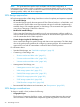
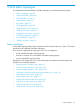
• Switch and hop counts Minimize the number of hops between devices that communicate regularly in the SAN. For information about switches and hop counts, see: • ◦ “B-series switches and fabric rules” (page 91) ◦ “C-series switches and fabric rules” (page 123) ◦ “H-series switches and fabric rules” (page 140) Oversubscription For improved performance, reduce the potential for oversubscription.
2 SAN fabric topologies This chapter discusses HP standard SAN fabric topologies.
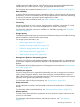
Routed SAN fabrics HP standard fabric topologies support Fibre Channel routing. Fibre Channel routing enables connectivity between devices in multiple fabrics, Virtual Fabrics, or multiple VSANs. HP supports the following routed fabric technologies: • “B-series Meta SAN” (page 35) • “C-series VSANs with IVR” (page 36) • “H-series switches with TR” (page 37) FCoE SAN fabrics HP standard fabric topologies can integrate with FCoE technology.
(32 to 40 ports), or a Core or Director switch (64 to 240 ports), which have higher port counts. For a high-availability SAN, use two switches configured in a dual-fabric SAN.
Switch models All HP Fibre Channel switches are supported for use in a cascaded fabric topology. Cascaded fabric topologies typically use the SN6000 Fibre Channel Switch; the 8/20q Fibre Channel Switch (or the HP Simple SAN Connectivity Kit); or SAN, Fabric, or Edge switches, which support smaller incremental growth. NOTE: Over time, a cascaded fabric topology can result in increased hops between switches. B-series, C-series, and H-series fabrics must not exceed seven hops.
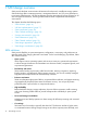
As you add switches, ISLs are connected to two or more adjacent switches to maintain mesh connectivity, ensuring path redundancy throughout the fabric (Figure 4). The additional ISL connectivity provides communicating devices with more paths through the fabric. This dramatically reduces the chance that, as you add switches, you will exceed the maximum hop count. Figure 4 ISL connections in a meshed fabric 25092a Switch models All HP Fibre Channel switches are supported for use in a meshed fabric topology.
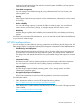
NOTE: HP does not recommend the ring fabric for applications requiring many-to-many connectivity. Figure 5 Ring fabric 25093a If the ring fabric has fewer than 12 switches, you can add switches (called satellite switches) outside the ring to create more user ports (Figure 6). Satellite switches are not supported. NOTE: Adding satellite switches slightly reduces fabric availability.
Figure 6 Ring fabric with satellite switches 25094a Switch models All HP Fibre Channel switches are supported for use in a ring fabric topology. Ring fabric topologies typically use the SN6000 Fibre Channel Switch; the 8/20q Fibre Channel Switch (or the HP Simple SAN Connectivity Kit); or SAN, Fabric, or Edge switches, which support smaller incremental growth. To meet higher port-count requirements, use Core or Director switches.
Figure 7 Core-edge fabric (typical depiction) 25095a Core-edge fabric topologies are typically depicted as shown in Figure 7 (page 30), but can also be depicted hierarchically as shown in Figure 8 (page 30). Both figures represent the same physical implementation. How a topology is logically represented can help you understand the potential performance of a core-edge topology.
Table 1 Core-edge fabric topology types Topology type Description Fat tree At least 50% of edge ports are dedicated as ISLs, resulting in an ISL ratio of 1:1. Skinny tree Less than 50% of edge ports are dedicated as ISLs, resulting in an ISL ratio of x:1, where x is 2 or more. Recommended ISL ratios The core-edge fabric type has a high fabric cross-sectional bandwidth (the maximum amount of data that can pass through ISLs at the fabric midpoint, which is the central connection or core of the fabric).
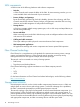
Figure 9 Core-edge fabric (4 x 12) 8 16 24 32 40 48 56 1 9 17 25 33 41 49 57 2 10 18 26 34 42 50 58 3 11 19 27 35 43 51 59 4 12 20 28 36 44 52 60 5 13 21 29 37 45 53 61 6 14 22 30 38 46 54 62 7 15 23 31 39 47 55 63 0 8 16 24 32 40 48 56 1 9 17 25 33 41 49 57 2 10 18 26 34 42 50 58 3 11 19 27 35 43 51 59 4 12 20 28 36 44 52 60 5 13 21 29 37 45 53 61 6 14 22 30 38 46 54 62 7 15 23 31 39
Table 3 (page 33) lists the data access performance ratings for each SAN fabric topology.
C-series switches Table 5 (page 34) lists the C-series switch and port maximums for specific fabric topologies.
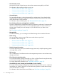
• “C-series VSANs with IVR” (page 36)—Implemented using C-series IVR. IVR provides selective Fibre Channel routing connectivity between devices in different VSANs. Ports on one or more switches can be assigned to different VSANs. • “H-series switches with TR” (page 37)—Implemented using the TR feature, which is available with firmware 8.x (or later).
Benefits A Meta SAN: • Allows fabric connections (without the need to merge fabrics), providing a high level of fault isolation and centralized fabric management • Connects multiple SAN islands (independent fabrics), enabling selective resource sharing • Eliminates the need to move and re-cable equipment in different fabrics • Allows connection of fabrics with the same domain ID and zoning definitions • Reduces the impact of scaling limits for individual fabrics • Increases levels of storage cons
Benefits A VSAN: • Isolates fabric services and minimizes fault propagation • Allows multiple secure VSANs over the same physical infrastructure • Restricts device access for improved control and security • Provides selective device access and sharing using the IVR feature H-series switches with TR The TR feature provides inter-fabric routing on a per-port basis, allowing controlled access between devices on an H-series switch (local) fabric and devices on a remote fabric consisting of B-series or C
Data availability SAN data availability depends on the reliability of the SAN fabric, servers, and storage systems during routine operations.
switch automatically reroutes data through an alternate fabric path and there is no interruption in server I/O activity. Figure 11 Level 2: single resilient fabric 25099a Level 3: single resilient fabric with multiple device paths Level 3 is the same as level 2 but also provides multiple server and storage system paths to the fabric to increase availability (Figure 12).
performance and a higher number of available ports, since all fabrics can be accessed simultaneously during normal operations. Figure 13 Level 4: multiple fabrics and device paths (NSPOF) A B 25101a Using two fabrics may increase implementation costs, but it also increases the total number of available ports. For example, in a single meshed fabric with four switches, you have a maximum of 52 user ports for servers and storage.
Table 8 Calculating for data availability levels Fabric design Hardware cost Number of available ports Level 1: single connectivity fabric x1 # ports = n – number of ISL ports2 Level 2: single resilient fabric x + additional ISLs # ports = n – number of ISL ports Level 3: single resilient fabric with multiple device paths x + additional ISLs + additional HBAs # ports = n – number of ISL ports – additional HBA ports3 Level 4: multiple fabrics and device paths (NSPOF) x + additional ISLs + additi
Migrating a meshed fabric SAN This section describes migration paths for a meshed fabric SAN. Meshed to ring You can migrate a meshed fabric SAN to a ring fabric SAN by removing the cross-connected ISLs and leaving the outer-connected ISLs as a ring. Use the available ports for device connections or for redundant ring ISL connections. Meshed to core-edge Use the method described in “Cascaded to core-edge” (page 41). Migrating a ring fabric SAN This section describes migration paths for a ring fabric SAN.
3 Fibre Channel routing This chapter describes Fibre Channel routing in an HP SAN environment.
• • Fabric, Virtual Fabric, or VSAN independence ◦ Isolation of fault domains ◦ Separate fabric services Centralized SAN fabric management ◦ Common fabric management ◦ Tape backup consolidation Fabric, Virtual Fabric, and VSAN independence Fibre Channel routing identifies data frames in a fabric, Virtual Fabric, or VSAN for transfer to other fabrics, Virtual Fabrics with IFR, or VSANs with IVR.
SAN scaling and routing This section describes two methods for increasing the size of SANs: • Increase the Fibre Channel switch capability within a fabric. • Connect independent fabrics using a Fibre Channel router, Virtual Fabrics with IFR, or VSANs with IVR. Switch scaling The switches that make up fabrics define the fabric limits. This section describes the relationship between switches.
Simple fabric services SNS provides a mapping between device names and their addresses in a fabric. To ensure that the mapping is up-to-date, every switch in the fabric implements SNS. Coordinating fabric services Each fabric maintains a unique set of fabric services. When two fabrics are connected, their two sets of services merge to form a single set. As fabrics grow, coordinating the fabric services across switches, hosts, and storage devices becomes more challenging.
◦ Multi-protocol Router Blade (MP Router Blade for the 4/256 SAN Director) ◦ Multi-protocol Router (MP Router) • A B-series switch with IFR connects multiple Virtual Fabrics, as shown in Figure 15 (page 47). • A C-series switch with IVR connects multiple VSANs, as shown in Figure 16 (page 47). • An H-series switch with TR connects to other B-series or C-series fabrics, as shown in Figure 17 (page 47).
B-series fabric groups In B-series routing configurations, devices in different fabrics can be grouped to form LSANs. An LSAN is similar to a Fibre Channel zone, but can extend through a router to include devices in other fabrics. This configuration, which includes the physical fabrics (subnetworks), LSANs, and router, is called a Meta SAN. A Meta SAN consolidates multiple fabrics into a single entity. Figure 14 (page 47) shows Fabric 1, Fabric 2, and Fabric 3, each containing one or more switches.
through one TR_Port. Multiple devices can share TR_Ports, and you can configure multiple TR_Ports to the same remote fabric. HP currently supports connection to B-series and C-series remote fabrics. Figure 17 (page 47) shows how one or more remote fabrics can connect to an H-series switch. Remote Fabric 1, Remote Fabric 2, and the H-series switch fabric each contain one or more switches. Devices connected through routing must comply with the configuration rules for the TR function.
Figure 19 B-series Virtual Fabric IFR LF1 LF3 LF3 LF1 LF2 LF2 LF3 LF1 LF2 25266b As shown in Figure 20 (page 50), VSANs can include devices that connect to a single switch or multiple switches in the SAN. Devices in different VSANs communicate using IVR. Multiple switches can be connected in any supported fabric configuration.
are the two devices and the TR_Port that connects them. CLI commands for adding this zone to the remote fabric zone set are generated automatically.
Figure 23 Dual-redundant Virtual Fabric FC Switch (IFR) VF A1 VF A2 IFR SAN A FC Switch (IFR) VF B1 VF B2 IFR SAN B 25267b Figure 24 Dual-redundant VSAN FC Switch (IVR) VSAN A1 VSAN A2 IVR SAN A FC Switch (IVR) VSAN B1 VSAN B2 IVR SAN B 25107b Supported routing configurations Routing requires additional configuration rules for fabrics.
Figure 25 1606 Extension SAN Switch or MP Router connecting core switches 1606 Extension SAN Switch, 400 MPR, or MPR (FC Routing) 25108c An alternative core switch routing configuration is to use the 8 Gb/s switch integrated Fibre Channel routing feature or MP Router Blades in the SAN Directors.
Figure 27 VSANs connecting core switches VSAN 3 VSAN 1 VSAN 2 VSAN 3 VSAN 2 VSAN 1 VSAN 3 VSAN 1 VSAN 2 25109a Routing through an IP network When connecting fabrics through IP, 1606 Extension SAN Switches or DC Dir Switch MP Extension Blades, MP Routers or Blades serve as FCIP gateways with Fibre Channel routing. Routers that communicate with the FCIP protocol must be installed in pairs (Figure 28 and Figure 29).
Figure 30 (page 55) shows IVR connecting VSANs through IP. Figure 30 IVR connecting VSANs through IP VSAN 1 VSAN 2 . . VSAN n VSAN 1 VSAN 2 . . VSAN n FC Switch (IVR) IP FCIP with IVR FC Switch (IVR) 25111a High-availability router configurations In high-availability configurations, use pairs of 8 Gb/s switches with integrated Fibre Channel routing, 1606 Extension SAN Switches, routers, or IFL pairs to provide redundant paths between fabrics.
Figure 31 High-availability 1606 Extension SAN Switch configurations 1606 Extension SAN Switch Fabric A1 Fabric A2 1606 Extension SAN Switch Fabric B1 Fabric B2 NSPOF configuration 1606 Extension SAN Switch Fabric A1 Fabric A2 1606 Extension SAN Switch Fabric B1 Fabric B2 1606 Extension SAN Switch Fabric A1 Fabric A2 26597b 56 Fibre Channel routing
Figure 32 High-availability MP Router configurations 400 MPR or MPR (FC Routing) Fabric A1 Fabric A2 400 MPR or MPR (FC Routing) Fabric B1 Fabric B2 NSPOF configuration 400 MPR or MPR (FC Routing) Fabric A1 Fabric A2 400 MPR or MPR (FC Routing) Fabric B1 Fabric B2 400 MPR or MPR (FC Routing) Fabric A1 Fabric A2 25112c 400 MP Router and MP Router Blade use cases For configuration examples, see the 400 MP Router and MP Router Blade use-case white papers: http://h18006.www1.hp.
Routing use cases This section describes use cases for routing. SAN island consolidation and scaling B-series routing consolidates SAN islands (multiple independent fabrics) into a Meta SAN. This modular SAN design offers: • Simplified scalability that allows you to scale a SAN without having to merge fabrics. • Selective sharing of devices in different fabrics so that only devices required for specific functions are seen across fabrics.
59) and Figure 37 (page 60) show a configuration in which the 1606 Extension SAN Switches or 400 MP Routers are used as both an FCIP gateway and Fibre Channel switch.
Figure 37 NSPOF configuration with 400 MP Router providing Fibre Channel routing and FCIP with direct connect devices 400 MPR 400 MPR VEX Fabric A1 IP A VE Fabric A2 FCIP with FC routing 400 MPR 400 MPR VEX Fabric B1 IP B VE Fabric B2 FCIP with FC routing 25282c Figure 38 NSPOF configuration with MP Router providing Fibre Channel routing and FCIP MPR Fabric A1 MPR Fabric A2 IP A FCIP with FC routing MPR Fabric B1 MPR IP B FCIP with FC routing Fabric B2 25114b Tape backup consolidation
Figure 39 1606 Extension SAN Switch or MP Router consolidating tape backup in a Meta SAN 1606 Extension SAN Switch, 400 MPR, or MPR (FC Routing) Fabric 2 Fabric 3 Fabric 1 Fabric 4 25115c Independent fabrics connected through a 1606 Extension SAN Switch or MP Router cannot have a direct ISL connection (Figure 40). A direct ISL connection between fabrics bypasses the MP Router, resulting in a full fabric merge.
4 Fibre Channel over Ethernet Fibre Channel over Ethernet is a protocol in which Fibre Channel frames can be sent over Ethernet networks. This allows Fibre Channel to use 10-GbE networks while preserving the Fibre Channel protocol. Simultaneously, the 10-GbE network supports Ethernet data thus creating a single converged network for Ethernet and Fibre Channel.
The HP FCoE module and switch product set consists of the following: • HP c-Class BladeSystem Virtual Connect FCoE capable modules: ◦ HP Virtual Connect FlexFabric 10Gb/24-Port Module for c-Class BladeSystem ◦ HP Virtual Connect Flex-10/10D Ethernet Module for c-Class BladeSystem • HP 6125XLG Ethernet Blade Switch—Provides a converged fabric solution that supports Ethernet, native FCoE, and iSCSI protocols that enables connectivity for FCoE or iSCSI storage solutions.
Fibre Channel ports on the HP B-series FCoE CN switches and HP C-series CN switches can be used for ISL connections to an existing Fibre Channel fabric, or to an HP Fibre Channel storage system or HBA. Table 9 (page 64) lists the number of ports for each HP FCoE CN switch.
• “HP StorageWorks DC SAN Director Switch 10/24 FCoE Blade” (page 67) • “HP C-series Nexus 5010/5020 Converged Network Switches” (page 67) • “Cisco Nexus 5548UP/5596UP Converged Network Switches” (page 68) • “HP CN1000E and CN1100E” (page 70) • “HP StoreFabric CN1100R” (page 71) • “HP CN1000Q” (page 71) • “FCoE storage systems” (page 71) Converged network switches and blades HP FlexFabric 5900CP Switch The HP FlexFabric 5900CP Switch is a ToR converged L2/L3 switch with 48 converged ports and
• Powerful QoS features: ◦ Creates traffic classes based on access control lists (ACLs), IEEE 802.1p precedence, IP, DSCP or Type of Service (ToS) precedence. ◦ Supports filter, redirect, mirror, or remark. ◦ Supports the following congestion actions: strict priority (SP) queuing, weighted round robin (WRR), weighted fair queuing (WFQ), weighted random early discard (WRED), weighted deficit round robin (WDRR), and SP+WDRR.
Considerations • The port types are fixed. You cannot use 10-GbE ports for FC connections, and you cannot use FC ports for 10-GbE connections. • L3 routing features are not currently supported. • 10-GbE ports support virtual F_Ports only (virtual E_Ports are not supported). HP StorageWorks DC SAN Director Switch 10/24 FCoE Blade The HP DC SAN Director Switch 10/24 FCoE Blade is a rebranded version of the Brocade FCOE10-24 blade.
Features • L2 access: ◦ IEEE DCB and FCoE support IEEE DCB is a Cisco unified fabric product with additional proprietary features.
• • Cisco Nexus 5596UP (2 RU) ◦ Up to 96 ports—48 unified ports and 3 16-port expansion modules ◦ 48 unified ports can be configured as 1- and 10-GbE and FCoE, or 8/4/2/1 Gb/s FC ports Optional expansion modules include: ◦ 16-port Unified Port Expansion Module—Up to 16 of 1/10 GbE FCoE ports or 16 of 8/4/2/1 Gb/s FC ports ◦ 8-port FC (8/4/2/1-Gb) + 8-port Ethernet and FCoE (1/10 GB) module Cisco Fabric Extender for HP BladeSystem The Cisco Fabric Extender for HP BladeSystem (Model B22HP) provide
Figure 41 FC and FCoE storage with Cisco Fabic Extender for HP BladeSystem configuration Blade servers with CNAs and Cisco Fabric Extender* for HP BladeSystem (*with C-series FCoE switches only) C-series FCoE switches FC switches 3PAR P6300 EVA P6500 EVA FCoE/iSCSI/FC EVA/SAS storage 10-GbE FCoE/iSCSI connection 10-GbE connection Fibre Channel 26663c Converged network adapters Servers with CNAs require fewer adapters per server and, therefore, 75% fewer cable connections for network and FC attachments.
Considerations • x8 PCI Express Gen2 card • Requires 14.5 W of power • 1 GbE is not supported HP StoreFabric CN1100R Features The HP StoreFabric CN1100R Dual Port CNA has the following features: • Ships with half-height and full-height brackets • Dual ports for redundancy • Full 10-Gb/s bandwidth on both ports • Each port can operate as a NIC and/or FCoE port • Two SFP+ connectors • Supports optical or copper cables Considerations • Requires an x8 PCI Express Gen2.
3PAR StoreServ 10400/10800/7200/7400/7450 with 10GbE FCoE host ports FCoE host ports For more information, see the 3PAR StoreServ FCoE product documentation. Operating system and multipath software support For the latest information on operating system and multipath software support, see the HP SPOCK website at http://www.hp.com/storage/spock. You must sign up for an HP Passport to enable access.
Table 11 P9500 10-GbE FCoE operating system and multipath software support Operating system Clusters P9500 storage system Multipath software Microsoft Windows Server 2008 MPIO with HP DSM (supports both CN1000E and CN1100E) MPIO with Microsoft DSM (supports both CN1000E and CN1100E) Microsoft Windows Server 2003 MPIO with HP DSM (supports CN1000E only) MPIO with Microsoft DSM (supports CN1000E only) Red Hat Linux, SUSE Linux Device Mapper None VMware VMware embedded None Microsoft Windows Ser
Operating system and multipath software support For the latest information on operating system and multipath software support, see the HP SPOCK website at http://www.hp.com/storage/spock. You must sign up for an HP Passport to enable access. Table 12 (page 74) provides the operating system and multipath software support for P63xx/P65xx EVA 10-GbE iSCSI/FCoE.
Figure 44 (page 75) depicts blade server FC/FCoE configurations with B-series, C-series, or HP FlexFabric FCoE switches and either Pass-Thru modules, 6120XG or 6125XLG DCB switches, or Virtual Connect modules. • If Pass-Thru modules are used, this configuration is supported with B-series or C-series FCoE and corresponding FC switches. • If 6120XG switches are used, this configuration is supported with C-series FCoE switches and FC switches only.
Figure 45 Blade server mixed FC/FCoE storage with HP 5820 switches Blade servers with CNAs and Pass-Thru modules or HP 5820* switches (*with B-series or C-series FCoE switches) FCoE switches FC switches 3PAR P63xx EVA P65xx EVA FCoE/iSCSI/FC EVA/SAS storage 10-GbE FCoE/iSCSI connection 10-GbE connection Fibre Channel 76 Fibre Channel over Ethernet 26667c
FCoE configuration rules This section describes configuration rules for the HP FCoE solution. The rules are defined for the CNAs and each of the FCoE CN switch series. Figure 46 (page 77) shows a converged SAN fabric with servers using CNAs only. NOTE: Fibre Channel HBAs can also be connected to B-series, C-series, or HP FlexFabric 5900CP converged ports as F_Ports.
Figure 47 (page 78) shows a converged SAN fabric with servers using CNAs connected to a B-series CN switch and a DC SAN Director Switch 10/24 FCoE Blade.
Figure 48 (page 79) shows a converged fabric that has servers with CNAs and servers with FC HBAs and NICs. NOTE: Fibre Channel HBAs can also be connected to B-series, C-series, , or HP FlexFabric 5900CP Converged Network switch F_Ports.
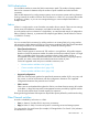
Figure 49 (page 80) shows an FCoE end-to-end direct-connect storage configuration using an MPX200 Multifunction Router and P6000/EVA Fibre Channel storage systems. This provides 10-GbE FCoE and iSCSI connectivity for up to two P6000/EVA Fibre Channel storage systems without requiring any Fibre Channel switches.
Figure 50 FCoE end-to-end MPX200 fabric-connect P6000/EVA FC storage configuration Servers with NICs Servers with CNAs FCoE/IP /iSCSI iSCSI/IP Converged network X-series CN switches IP FCoE/iSCSI MPX200 FCoE/iSCSI target HP StorageWorks MPX200 MGMT 10GbE4 IOIOI FC1 10GbE3 HP StorageWorks MPX200 10 - 1 GbE Blade MPX200 Multifunction Router FC2 GE1 GE2 MGMT 10GbE4 IOIOI FC1 10GbE3 Ethernet network 10 - 1 GbE Blade MPX200 Multifunction Router FC2 GE1 GE2 Fibre Channel Fabric B Fabri
CNA configuration rules Table 13 HP CNA requirements Item Description Number of CNAs per server (maximum) 2 • SFP+ optical: CN1100E, CN1100R, and CN1000Q 100m; CN1000E 40m Cable types and distances • Copper: CN1100R 5m; CN1100E, CN1000E, and CN1000Q 7m and 10m (with C-series FCoE CN switches only) For current firmware and driver support, see the HP SPOCK website at http://www.hp.com/ storage/spock. You must sign up for an HP Passport to enable access.
Table 14 HP 5820X CN switch fabric rules (continued) Rule number 6 Description Up to two 5820 FCoE modules are supported in a single 5820X switch. However, when using two A5280 FCoE modules, consider the following: • When two 5820 FCoE modules are connected to the same SAN, the FCoE modules attempt to load balance the server load across the two FCoE modules as servers are added by distributing the CNA logins between the two modules.
• Integrated Fibre Channel routing • FICON • Admin Domains • TI Zones • M-EOS Interop • Nondisruptive firmware upgrade Table 16 (page 84) provides a comparison of the high-availability features for the B-series FCoE CN switch.
ports are dual speed, supporting both 10-GbE and 1-GbE. The switch has one expansion slot that can accommodate up to 8 Fibre Channel switch ports. Expansion modules for the C-series Nexus 5000 Series switches The C-series Nexus 5000 Series switches can accommodate expansion modules that connect Fibre Channel SANs to 8, 4, 2, or 1 Gb/s Fibre Channel switch ports. Use these modules to increase the number of 10-GbE, Cisco IEEE DCB, and FCoE ports.
Table 17 Nexus switches for NX-OS Maximum number of Fibre Channel ports Maximum number of Ethernet ports C-series Nexus 5020 16 52 C-series Nexus 5010 8 26 Cisco Nexus 5548UP 48 with expansion module 48 with expansion module Cisco Nexus 5596UP 96 with expansion modules 96 with expansion modules Switch Table 18 (page 86) describes Nexus expansion module support.
Table 19 C-series Nexus 5000 series and Cisco Nexus 5500 series switch high-availability feature comparison Redundant/ hot-swappable power Redundant/ hot-swappable cooling Redundant control processor Nondisruptive code activation Expansion module support Nexus 5020 Yes/Yes Yes/Yes No No Yes Nexus 5010 Yes/Yes Yes/Yes No No Yes Nexus 5548UP Yes/Yes Yes/Yes No No Yes Nexus 5596UP Yes/Yes Yes/Yes No No Yes Switch Protocol support FCIEEE DCB 10-GbE FCoE FCFCoECEE compliant DCBX Us
Windows 2003 (x86, x64) and 2008 (x86, x64) • BFS is supported on all supported HP servers. • The information in HP Boot from SAN Configuration Guide is accurate for Windows BFS on a CNA based server for Windows 2003 with the following exceptions: ◦ You must install an HP CNA driver kit, available for download at the HP website:http:// www.hp.com/support/downloads ◦ For Windows 2003, press F6 to prompt for the driver disk.
SUSE Linux Enterprise Server • BFS is supported on all supported HP servers. • The information in HP Boot from SAN Configuration Guide is accurate for BFS on a CNA based server with the following exception: ◦ Use the GUI to load the driver. See Figure 52. Figure 52 SLES installation The HP Boot from SAN Configuration Guide is available at http://h18006.www1.hp.com/storage/ networking/bootsan.html. Under Features, click Boot from SAN documentation.