HP SC08Ge Host Bus Adapter Installation Guide Part Number 493938-001 June 2008 (First Edition)
© Copyright 2008 Hewlett-Packard Development Company, L.P. The information contained herein is subject to change without notice. The only warranties for HP products and services are set forth in the express warranty statements accompanying such products and services. Nothing herein should be construed as constituting an additional warranty. HP shall not be liable for technical or editorial errors or omissions contained herein. Microsoft and Windows are U.S. registered trademarks of Microsoft Corporation.
Contents Features....................................................................................................................................... 4 Board features .......................................................................................................................................... 4 Summary of specifications .......................................................................................................................... 4 Installation procedure .........................
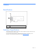
Features Board features Item Description 1 Two external mini SAS 4x connectors Summary of specifications The HP SC08Ge Host Bus Adapter is a low-profile, 64-bit PCIe adapter that supports transfer rates of up to 3 Gb/s for SAS and 1.5 Gb/s for SATA. For more information about the features, specifications, and compatibility of the adapter, see the QuickSpecs on the product-specific page of the HP website (http://www.hp.com).
Installation procedure Installation overview WARNING: To reduce the risk of personal injury or damage to the equipment, consult the safety information and user documentation provided with the server before attempting the installation. Many servers are capable of providing energy levels that are considered hazardous and are intended to be serviced only by qualified personnel who have been trained to deal with these hazards.
For more information, see "Electrostatic Discharge (on page 13)." 1. Depending on the server model, remove or open the server access panel. WARNING: To reduce the risk of personal injury from hot surfaces, allow the drives and the internal system components to cool before touching them. 2. Locate the PCIe bus expansion slots, and select the slot that you want to use. (For more information, see the server documentation.) 3.
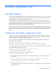
SAS BIOS configuration utility SAS BIOS features The SAS BIOS is the bootable ROM code that manages SAS hardware resources. It is specific to a family of SAS controllers and processors. The SAS BIOS integrates with a standard system BIOS, extending the standard disk-service routine provided through INT13h. During initialization, the SAS BIOS determines if the system BIOS has already installed other hard disks, such as an IDE drive.
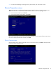
The SAS BIOS configuration utility can detect devices that the SAS BIOS cannot control (for example, tape drives and scanners). However, the configuration utility can still be used to modify certain parameters for these devices. Configuration utility screens All SAS BIOS configuration utility screens contain the following areas, starting at the top of the screen: • Header—Identifies the utility and version number.
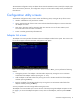
Adapter Properties screen The Adapter Properties screen provides information about the adapter, and gives you access to other screens that enable you to view information about devices connected to the adapter. To view information about devices connected to the adapter, move the cursor to the SAS Topology field, and then press the Enter key.
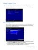
• To clear Device Mappings for missing devices, press C at any time while on this screen. Device Properties screen The Device Properties screen displays information about a specific device. To access this screen, press Alt+D when the cursor is in the Device Identifier field of a device on the SAS Topology screen. • To move to the next device, press Alt+N. • To move back to the previous device, press Alt+P. This screen also provides access to the Format and Verify screens.
CAUTION: After a format is started it cannot be paused or cancelled. To begin the format, press F. The formatting procedure sets the sector size to 512 bytes, even if the drive was previously formatted to another sector size. This is the only sector size that the SAS BIOS configuration utility supports on RAID volumes. Device Verify screen Use the Device Verify screen to verify a particular device. To access this screen, press Enter in the appropriate field on the Device Properties screen.
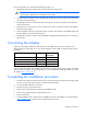
Exit Menu screen The SAS BIOS configuration utility must be exited properly because some changes take effect only during the exit process. To access the Exit Menu screen, press Esc from any screen in the utility. If an option is not relevant or not available, it is deactivated. Performing configuration tasks Locating a disk drive There are two ways to physically locate a disk drive: • On the Create New Array screen, the drive locator LED is on when a drive is selected to be part of a RAID volume.
Electrostatic discharge Preventing electrostatic discharge To prevent damaging the system, be aware of the precautions you need to follow when setting up the system or handling parts. A discharge of static electricity from a finger or other conductor may damage system boards or other static-sensitive devices. This type of damage may reduce the life expectancy of the device. To prevent electrostatic damage: • Avoid hand contact by transporting and storing products in static-safe containers.
Regulatory compliance notices Federal Communications Commission notice Part 15 of the Federal Communications Commission (FCC) Rules and Regulations has established Radio Frequency (RF) emission limits to provide an interference-free radio frequency spectrum. Many electronic devices, including computers, generate RF energy incidental to their intended function and are, therefore, covered by these rules.
• Connect the equipment into an outlet on a circuit that is different from that to which the receiver is connected. • Consult the dealer or an experienced radio or television technician for help. Declaration of conformity for products marked with the FCC logo, United States only This device complies with Part 15 of the FCC Rules.
This Class B digital apparatus meets all requirements of the Canadian Interference-Causing Equipment Regulations. Cet appareil numérique de la classe B respecte toutes les exigences du Règlement sur le matériel brouilleur du Canada.
Japanese notice Korean notice Class A equipment Class B equipment Regulatory compliance notices 17
Acronyms and abbreviations LBA logical block addressing NVRAM non-volatile memory RBSU ROM-Based Setup Utility SAS serial attached SCSI SATA serial ATA Acronyms and abbreviations 18