User's Manual HP 9000 Model A-180 Manufacturing Part Number : Z4045-90002 February 2000
Notice Hewlett-Packard makes no warranty of any kind with regard to this material, including but not limited to, the implied warranties of merchantability and fitness for a particular purpose. Hewlett-Packard shall not be liable for errors contained herein or for incidental or consequential damages in connection with the furnishing, performance, or use of this material. Hewlett-Packard assumes no responsibility for the use or reliability of its software on equipment that is not furnished by Hewlett-Packard.
Contents 1. A-Class System Overview and Reference A-Class Server - System Overview . . . . . . . . . . . . . . . . . . . . . . . . . . . . . . . . . . . . . . . . . . . . . . . . . . . . . . System Hardware Overview. . . . . . . . . . . . . . . . . . . . . . . . . . . . . . . . . . . . . . . . . . . . . . . . . . . . . . . . . . System Software Overview. . . . . . . . . . . . . . . . . . . . . . . . . . . . . . . . . . . . . . . . . . . . . . . . . . . . . . . . . . .
Contents A-Class Server System Software Configuration . . . . . . . . . . . . . . . . . . . . . . . . . . . . . . . . . . . . . . . . . . . 59 Overview . . . . . . . . . . . . . . . . . . . . . . . . . . . . . . . . . . . . . . . . . . . . . . . . . . . . . . . . . . . . . . . . . . . . . . . . . 59 3. A-Class System Service A-Class System Repair . . . . . . . . . . . . . . . . . . . . . . . . . . . . . . . . . . . . . . . . . . . . . . . . . . . . . . . . . . . . . . . Overview . . . . . . . . . . . . . .
Contents A-Class Server I/O Card Removal and Replacement . . . . . . . . . . . . . . . . . . . . . . . . . . . . . . . . . . . . . . . 97 Introduction. . . . . . . . . . . . . . . . . . . . . . . . . . . . . . . . . . . . . . . . . . . . . . . . . . . . . . . . . . . . . . . . . . . . . . . 97 Electrostatic Discharge Precautions . . . . . . . . . . . . . . . . . . . . . . . . . . . . . . . . . . . . . . . . . . . . . . . . . . . 97 Before You Do Anything... . . . . . . . . . . . . . . . . . . . . . . . . .
Contents 8
A-Class System Overview and Reference 1 Chapter 1 A-Class System Overview and Reference 9
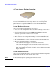
A-Class System Overview and Reference A-Class Server - System Overview A-Class Server - System Overview The A-Class server is a compact addition to the HP9000 server family, targeted at the ISP server market. The A-Class server design allows the use of existing qualified peripherals and I/O add-in options. It is a PCXL-2 (PA-7300 RISC Processor) based platform designed to support the UNIX Internet Service Provider (ISP) market.
A-Class System Overview and Reference A-Class Server Service Reference Information A-Class Server Service Reference Information Overview Service reference data consists of the following: Chapter 1 • 11”x14” maintenance label • A A-Class Server System Block Diagram for maintenance personnel and operators. • The A-Class Server System Regulatory Compliance Statements required by the U. S. government and required by some countries that import HP products.
A-Class System Overview and Reference A-Class Server System Block Diagram A-Class Server System Block Diagram Overview The A-Class server block diagram is included for information.
A-Class System Overview and Reference A-Class Server System Regulatory Compliance Statements A-Class Server System Regulatory Compliance Statements Overview Regulatory Compliance statements are required by some countries for international importation of A-Class servers.
A-Class System Overview and Reference A-Class Server System Regulatory Compliance Statements Regulatory Information For your protection, this product has been tested for conformance to various national and international regulations and standards. The scope of this regulatory testing includes electrical and mechanical safety, electromagnetic emissions, immunity, acoustics and hazardous materials. When required, approvals are obtained from third party test agencies.
A-Class System Overview and Reference A-Class Server System Regulatory Compliance Statements Declaration of Conformity FCC STATEMENT (USA Only) The United States Federal Communications Commission has specified that the following notice be brought to the attention of users of this product: NOTE This equipment has been tested and found to comply with the limits for a Class A digital device, pursuant to part 15 of the FCC rules.
A-Class System Overview and Reference A-Class Server System Regulatory Compliance Statements for repair and/or warranty information. If the trouble is causing harm to the telephone network, the telephone company may request that you remove the equipment from the network until the problem is resolved. • No repairs are to be made by you. Repairs are to be made only by Hewlett-Packard or its licensees. Unauthorized repairs void registration and warranty.
A-Class System Overview and Reference A-Class Server System Regulatory Compliance Statements Japan RFI Statement Korean RFI Statement Taiwan RFI Statement Japan-Only JATE Mark Japan Harmonic Statement Chapter 1 17
A-Class System Overview and Reference A-Class Server System Regulatory Compliance Statements Acoustics (Germany) Acoustic noise level per ISO 9296 (25° C): LpAm <57dB (operators position) GerÌuschemission nach ISO 9296 (25° C): LpAm <57dB (Arbeitsplatte) UK General Approval (United Kingdom only) Pursuant to Section 22 of Telecommunications Act of 1984, this product is approved for indirect connection to Public Telecommunications systems within the United Kingdom under the General Approval number NS/G/12
A-Class System Overview and Reference A-Class Server System Regulatory Compliance Statements CAUTION Users should not attempt to make such connections themselves, but should contact the appropriate electric inspection authority, or electrician, as appropriate. National Post and Telecom Agency Statement (Sweden only) The LAM Interface shall be connected to SELV (max.42.4 V peak, or 60 V DC) according to EN 60950. (The internal modem complies with this requirement.
A-Class System Overview and Reference A-Class Server System Regulatory Compliance Statements The operation of this equipment on the same line as telephones or other equipment with audible warning devices or automatic ring detectors will give rise to bell tinkle or noise and may cause false tripping of the ring detector. Should such problems occur, the user is not to contact Telecom Faults Service.
A-Class Server Installation 2 Chapter 2 A-Class Server Installation 21
A-Class Server Installation A-Class Server System Installation A-Class Server System Installation Overview The sections listed below describe the procedures you will use to prepare for, install, and begin operation of, your A-Class server: A-Class Server Site Preparation. Contains environmental requirements for preparing the area where your server is to be located. Stand-Alone A-Class Server Unpack and Install Instructions.
A-Class Server Installation A-Class Server Site Preparation A-Class Server Site Preparation Overview This section contains the following environmental requirements for preparing a site for the A-Class Server: Space Requirements. Space requirements for both stand-alone and cabinet-mounted A-Class servers. Input Power Requirements. Nominal input voltage, nominal frequency, and typical current requirements. Cooling Requirements.
A-Class Server Installation A-Class Server Site Preparation 23” (58.42cm) Stand-Alone Server Minimum Service Access Requirements Access Location CAUTION Rear 15 cm (6 in.) Sides 7.5 cm (3 in.) Front 7.5 cm (3 in.) Stacking A-Class servers in any manner and mounting in any cabinet other than a Hewlett-Packard approved cabinet, is not supported. While they are constructed to be strong, A-Class servers have not been tested for stacking load carrying capacity.
A-Class Server Installation A-Class Server Site Preparation Cabinet Product Number Description Max. A-Clas s Server s EI A External Dimensions (width x depth x height) Centimeters Inches A4901A Factory Integrated 1.6m x 19” Cabinet 33 16 59.7 x 100.3 x 161.3 23.5 x 39.5 x 63.5 A4902A Factory Integrated 2.0m x 19” Cabinet 41 20 59.7 x 100.3 x 196.9 23.5 x 39.5 x 77.5 J1502A Field Integrated 1.25m x 19” Cabinet 25 12 59.7 x 100.3 x 125.7 23.5 x 39.5 x 49.5 J1501A Field Integrated 1.
A-Class Server Installation A-Class Server Site Preparation • Nominal Frequency: 50 or 60 Hz • Typical current requirements: 1.0A at 100V 0.43A at 240V. If an Uninterruptible Power Supply (UPS) is to be used, ensure that it is properly connected to the server. Refer to the, External Connections section for UPS information. Power cord plugs for stand-alone servers are configured to meet unique power configurations used all over the world.
A-Class Server Installation Stand-Alone A-Class Server Unpack and Install Instructions Stand-Alone A-Class Server Unpack and Install Instructions Overview Unpacking the A-Class server consists of opening and unloading the carton. Inside the carton you will find, in addition to the server, an accessory kit and a packet containing installation instructions and regulatory information.
A-Class Server Installation Stand-Alone A-Class Server Unpack and Install Instructions Unpack the Server CAUTION Do not set the server on its side, or in any position other than upright on its rubber “feet,” for operation. Failure to observe this precaution may result in component damage or loss of system reliability. Carefully unwrap the server and set it upright on the work surface. Open the Accessory Kit Open the Accessory Kit and verify that the contents agree with the packing list.
A-Class Server Installation Cabinet-Mounted A-Class Server System Unpack and Install Cabinet-Mounted A-Class Server System Unpack and Install Overview A-Class servers can be procured in two modes: stand-alone or pre-installed in a cabinet at the factory. Stand-alone servers can be configured for installation in an existing HP-supported cabinet.
A-Class Server Installation Cabinet-Mounted A-Class Server System Unpack and Install WARNING Wear protective glasses while cutting the plastic bands around the shipping container. These bands are under tension. Failure to heed this warning can result in serious eye injury if the bands snap back and hit you in the face when cut. Step 1. Cut the plastic polystrap bands around the shipping container. Step 2.
A-Class Server Installation Cabinet-Mounted A-Class Server System Unpack and Install Step 3. Remove the brackets securing the cabinet to the pallet (callout 4). 4 4 4 Step 4. Insert the ramps in the notches provided on the pallet (callout 5). Remove the side panels from the cabinet and set them aside (callout 6).
A-Class Server Installation Cabinet-Mounted A-Class Server System Unpack and Install WARNING A fully configured 2.0 meter cabinet can weigh up to 362.8 kg (800 lbs). Always use at least two people to roll the cabinet off of the pallet. Failure to heed this warning can result in serious injury or equipment destruction. Step 5. Use at least two people to roll the cabinet off of the pallet and down the ramp (callout 7).
A-Class Server Installation Cabinet-Mounted A-Class Server System Unpack and Install • Check the rear door for dents, scratches, proper fit when its closed, and operation. Cabinet Interior Checklist: Open the rear door and inspect the inside of the cabinet: NOTE • Inspect all cables, make sure they are secure. • Inspect all rails for signs of damage. • Check all mounting screws for tightness. • Check all components for signs of shifting during shipment or any signs of damage.
A-Class Server Installation Cabinet-Mounted A-Class Server System Unpack and Install The cabinet/server system assembly is now ready for the power up process. Refer to the section titled, A-Class Server Power Up and Boot Procedures. PowerTrust UPS Option Unpack the PowerTrust UPS and read all the installation information in the PowerTrust System Guide, part number 5961-8383.
A-Class Server Installation Cabinet-Mounted A-Class Server System Unpack and Install pallet. Contact your local Hewlett-Packard Sales and Support Office regarding shipment. Failure to heed this warning can result in serious injury or equipment destruction. To repackage the cabinet, follow the repacking checklist and refer to the unpacking instructions for detail. Repacking Checklist: • Assemble the HP packing materials that came with the cabinet. • Connect the loading ramp to the pallet.
A-Class Server Installation Cabinet-Mounted A-Class Server System Unpack and Install Cabinet Product Number C2787A Assembl ed by: Field Size (Height x Width) 2.0m x 19” Maximum Servers 20 Adapter Kit Number A5214A Cabinet Loading Requirements A-Class servers require two EIA of cabinet space (each two EIA of space is equivalent to the height of a server without the server’s “feet”). Ensure that the cabinet has this amount of space available.
A-Class Server Installation Cabinet-Mounted A-Class Server System Unpack and Install • Hold the tabs upright and slide the server all the way into cabinet until the tabs butt up against the columns on each side. Step 4. Fasten the both front anchor brackets securely to both front cabinet columns with the prepositioned sheet metal nuts. Step 5. Attach a plastic end cap to each anchor bracket. Step 6. At the rear of the cabinet, position the rear rail mounting clamps on each rail at the back of the server.
A-Class Server Installation Cabinet-Mounted A-Class Server System Unpack and Install External Connections External devices are interfaced with the A-Class server by means of specific connectors located in the rear of the server. Exterior connections to the server include ports for: • Small Computer System Interface (SCSI) devices • System Consoles • Local Area Networks (LANs) • Power Cords.
A-Class Server Installation Cabinet-Mounted A-Class Server System Unpack and Install Connect external DDS (Digital Data Storage) tape and DVD/ CDROM drives to A-Class servers as shown in the diagram below. Connecting these devices in this manner reduces the likelihood of excessive parity errors and unexpected interrupts from occurring on the SCSI bus. Connect a System Console • Using the ASCII Terminal as a System Console.
A-Class Server Installation Cabinet-Mounted A-Class Server System Unpack and Install Connect Power Cords CAUTION Do not press and hold the Web Console Reset button (located on the rear of the server between the LAN Web Console receptacle and the ASCII terminal receptacle) while connecting the server power cord. Failure to observe this precaution will cause erasure of all settings in the Web Console that is connected to the server. Connect the power cord that is provided with the system to the server.
A-Class Server Installation Installing Internal Add-On Components Installing Internal Add-On Components This section explains how to install internal add-on components into A-Class servers. Internal add-on components include memory, cache memory, embedded disks and I/O cards. For cabinet mounted servers, it is necessary to remove the server from the cabinet to install internal add-on components.
A-Class Server Installation Installing Internal Add-On Components Electrostatic Discharge Precautions. The procedures in this section require opening the server and exposing the system to electrostatic discharge. Always observe all electrostatic precautions when working with components inside or out of the server. Failure to follow these precautions may result in component damage or loss of system reliability. • Use a grounding mat and an anti-static wrist strap.
A-Class Server Installation Installing Internal Add-On Components A-Class servers provide 2 slots for Cache Memory. The following rules govern the installation memory in A-Class Servers. • Cache Memory must be installed in SIMM pairs. • The capacity of SIMMs must be the same. Follow the steps below to install Cache Memory in A-Class servers. Electrostatic Discharge Precautions. The procedures in this section require opening the server and exposing the system to electrostatic discharge.
A-Class Server Installation Installing Internal Add-On Components • Use a grounding mat and an anti-static wrist strap. • Wear the anti-static wrist strap to ensure that any accumulated electrostatic charge is discharged from your body to ground. Before You Do Anything... • Power down the system. • Unplug the server. Cabinet-mounted servers must be removed from the cabinet before proceeding.
A-Class Server Installation Installing Internal Add-On Components Set the upper drive to ID to 5 Set the lower drive to ID to 6 Step 5. Install the first embedded disk drive in the lower slot and the second embedded disk in the upper slot of the disk carrier. Orient the disk drive and the carrier such that the power and data connectors on the disk drive are on the same side as the sheetmetal tabs.
A-Class Server Installation Installing Internal Add-On Components Step 7. Install the disk carrier by inserting the two sheetmetal tabs on the disk carrier into the cut-outs in the server chassis. Secure the disk carrier using the slotted T15 TORX screw removed in step 1. Step 8. Proceed to A-Class Server Power Up and Boot Procedures. Installing Input/Output (I/O) Cards. This section describes how to install I/O cards into A-Class servers.
A-Class Server Installation Installing Internal Add-On Components Example: A3342A is not installed. ‘CONSOLE PATH’ value is 8/16/4. Server firmware directs output to 8/16/4.0. Install A3342A. The ‘CONSOLE PATH’ value is still 8/16/4 but server firmware directs output to 8/4/0.0. Where the console is connected never changes. NOTE When the A3342A HSC Remote Management card is installed, do not move the console cable from the server connector labeled “Console 8/16/4.
A-Class Server Installation Installing Internal Add-On Components • Use a grounding mat and an anti-static wrist strap. • Wear the anti-static wrist strap to ensure that any accumulated electrostatic charge is discharged from your body to ground. Before You Do Anything... • Power down the system. • Unplug the server. Cabinet-mounted servers must be removed from the cabinet before proceeding.
A-Class Server Installation A-Class Server Power Up and Boot Procedures A-Class Server Power Up and Boot Procedures Overview This Section discusses the following power up and boot procedures: • Power Up All External Devices • Power Up the Server • Configuring the integrated A-Class Web Console.
A-Class Server Installation A-Class Server Power Up and Boot Procedures Configuring the integrated A-Class Web Console CAUTION The integrated A-Class Web Console is preconfigured with IP address 192.0.0.192. Power-off any other devices with the same IP address before proceeding with integrated A-Class Web Console configuration. Each A-Class server must be configured to the integrated A-Class Web Console with an individual IP address.
A-Class Server Installation A-Class Server Power Up and Boot Procedures Configure the Web Browser Enable Java™ on your Web browser (Internet Explorer™ version 3.02 or Netscape Navigator™, version 3.01 or later). Temporarily add 192.0.0.192 to the list of URLs in your browser proxy configuration (under options). Configure The integrated A-Class Web Console Software NOTE During the configuration of your Secure web console, you must construct an IP gateway in the “configure IP” screen.
A-Class Server Installation A-Class Server Power Up and Boot Procedures Press OK to continue. The following administrator account creation screen will appear: The data required for this screen is defined below: Name is the full name of the Secure Web Console Administrator. Function is the job title of the Secure Web Console Administrator. Information can be used for additional data about the Secure Web Console Administrator. For example: phone number, location, etc.
A-Class Server Installation A-Class Server Power Up and Boot Procedures When all fields have been completed, the following “Configure IP” screen will appear: The data required for this screen is defined below: Chapter 2 • Secure Console Name (the name given to the integrated A-Class Web Console) • IP address (the IP for the integrated A-Class Web Console port) • IP subnet mask (the IP for the subnet mask for your site) • IP gateway (the IP gateway address) • System name (the name given to the A-
A-Class Server Installation A-Class Server Power Up and Boot Procedures After entering this information, press OK. The final screen in this series will appear: NOTE Disregard step 2, “Connect the serial cable from the system to the Secure Web Console.” Step 2 applies only to the stand-alone version of the HP Secure Web Console product. In A-class servers, this product is already installed internally. Press OK to continue. NOTE Pressing OK will NOT reboot the A-Class server.
A-Class Server Installation A-Class Server Power Up and Boot Procedures Configuring the Web Console To configure the Web console for other A-Class servers, repeat all of the steps in this section. Use arp -a to display arp entries and use arp-d to delete the previous entry for IP 192.0.0.192. For example, to configure the Web Console for A-Class servers with MAC addresses of 0060b0a60ale and 001083a62a3e using a PC with an IP of 15.43.251.93, proceed as follows: At the C:\> prompt, type: route add 192.0.0.
A-Class Server Installation A-Class Server Power Up and Boot Procedures Reply from 192.0.0.192: bytes=32 time=10ms TTL=255 Reply from 192.0.0.192: bytes=32 time=10ms TTL=255 Reply from 192.0.0.192: bytes=32 time=10ms TTL=255 Return to Configure the Web Browser and Configure The integrated A-Class Web Console Software. Operating System Software Installation HP-UX may be installed from removable media (DDS or CDROM) or via a LAN (Ignite-UX). A-Class servers require a server firmware version of 39.
A-Class Server Installation A-Class Server Power Up and Boot Procedures INSTALL HP-UX Press Enter. The console will display another menu. Select: STANDARD LVM CONFIGURATION Press Enter. The console will display another menu. To the query: INTERACT WITH SD-UX? type: no Press Enter. The system will begin the software installation process. Step 2.
A-Class Server Installation A-Class Server Power Up and Boot Procedures Step 7. To add “btlan3” driver support to the kernel, edit the /stand/system file and add the line: btlan3. To access the file, type the following command when the system prompt “#” displays: vi /stand/system. When the file opens, add the “btlan3” line. Step 8. Now, rebuild the kernel and reboot the system. Type the following command when the system prompt “#” displays: mk_kernel -o /stand/vmunix Press Enter.
A-Class Server Installation A-Class Server System Software Configuration A-Class Server System Software Configuration Overview Instructions for configuring software for both the A-Class server and the A-Class Secure Web Console can be found at: http:/docs.hp.com/. For hardware configuration, refer to Chapter 3, “A-Class System Service,” on page 61.
A-Class Server Installation A-Class Server System Software Configuration 60 Chapter 2
A-Class System Service 3 Chapter 3 A-Class System Service 61
A-Class System Service A-Class System Repair A-Class System Repair Overview The sections listed below describe the procedures you will use to identify fault conditions in your server, troubleshoot the system, exchange the server Field Replaceable Units (FRUs), and configure system hardware: • “A-Class System Repair”. Describes the LED patterns displayed during normal operation and when fault conditions occur. • “A-Class Server Fault Condition Recognition”.
A-Class System Service A-Class Server Fault Condition Recognition A-Class Server Fault Condition Recognition Overview The existence of fault conditions are determined by reviewing Front Panel LED Status codes (shown below), or reviewing Review Console Messages. The following subsections describe fault condition review procedures. Review Front Panel Status LEDs Front panel LEDs display either normal operation or fault status of the A-Class server.
A-Class System Service A-Class Server Fault Condition Recognition Review Console Messages Console messages are also used to display fault conditions on the system console if a System Panic or HPMC fault occurs. If the memory dump function is properly configured, a memory dump (core dump) will automatically print to a hard disk file or other designated data storage following a System Panic, HPMC fault, or Transfer Of Control (TOC).
A-Class System Service A-Class Server Trouble Shooting A-Class Server Trouble Shooting Overview Troubleshooting an A-Class server is performed to the “Field Replaceable Unit” (FRU) level. Diagnostic testing can be performed on the A-Class server and most components can be removed and replaced by the customer or customer representative. NOTE The information in this section is meant for users who have at least a minimum level of hardware troubleshooting experience.
A-Class System Service A-Class Server Trouble Shooting A-Class Server Selftest Failures/Warnings A power-on selftest is conducted each time power is applied to the server. Failures that occur at this point will either prevent selftest from completing or, upon initial completion of selftest, display warnings on the console. NOTE Warnings will include a brief description of the fault.
A-Class System Service A-Class Server Trouble Shooting NOTE The LED pattern is only valid if the Firmware Main Menu is not displayed at the Console.
A-Class System Service A-Class Server Trouble Shooting • Use a grounding mat and an anti-static wrist strap. • Wear the anti-static wrist strap to ensure that any accumulated electrostatic charge is discharged from your body to ground. Before You Do Anything... • Power down the system. • Unplug the server. NOTE Cabinet-mounted servers must be removed from the cabinet before proceeding. • Remove the top of the server by unscrewing the knurled captive screws on each side of the rear of the server.
A-Class System Service A-Class Server Trouble Shooting Random Access Memory (RAM) Module Fault. This fault occurs when a RAM failure prevents the system from completing selftest. Chassis codes provided by the HSC Remote Management card are useful in troubleshooting this type of error. For example, FLT 7xxx indicates a failure in the memory selftest. NOTE SIMM is an acronym for Single Inline Memory Module. A SIMM has components on one side of the card, only.DIMM is an acronym for Dual Inline Memory Module.
A-Class System Service A-Class Server Trouble Shooting Step 2. If the fault does not recur, the problem was caused by the SIMM that is not presently installed. Boot the system and resume normal operations. If the fault recurs, proceed to step 3. Step 3. Power down the server and replace the RAM SIMM in slot B with the other original RAM SIMM. Power up and observe front panel LEDs. Step 4. If the fault does not recur, the problem is with the RAM SIMM that was previously installed in slot B.
A-Class System Service A-Class Server Trouble Shooting Step 5. If the fault recurs, the I/O card in the bottom slot is the cause of the I/O Subsystem or I/O Board Fault. Replace that I/O board. Step 6. If the fault does not recur, install the second I/O card, power up the server, and observe the front panel LEDs. Step 7. If the problem recurs, replace the top I/O card. Step 8. If replacing the I/O card does not clear the I/O Subsystem or I/O Board Fault, the problem is with the system board.
A-Class System Service A-Class Server Trouble Shooting Second Level Cache Memory HPMC Fault. SLC faults occur when an HPMC, in response to a SLC failure, prevents the system from completing selftest. Chassis codes provided by the HSC Remote Management card are useful in troubleshooting this type of error. If power cycling the server clears the fault, continue troubleshooting by using the “ser pim” command at the firmware main menu screen.
A-Class System Service A-Class Server Trouble Shooting Firmware Warning Messages Description/Action Required WARNING: FAN FAILURE HAS BEEN DETECTED. THE SYSTEM WILL BE POWERING DOWN. PLEASE CALL YOUR SERVICE REPRESENTATIVE A chassis fan failure requires replacing the EBU. ERROR: A3342A AP Card must be in bottom slot only. Move the AP A3342A card to the bottom slot. ERROR: HSC card in wrong slot. Move to bottom slot. A mix of HSC and PCI cards has been detected.
A-Class System Service A-Class Server Trouble Shooting The HSC Remote Management card shows status information on the console just above the function key display (shown above) and is followed by the CM> prompt. The information displayed is shown below: OSTAT Chassis Code REMOTE : stat us activit y password ACCESS FAULT: CM> HSC Remote Management status information is defined as follows: Status Code Definition OSTAT Operating STATus. Values can be OFF, FLT, TEST, INIT, SHUT, WARN RUN and ALL.
A-Class System Service A-Class Server Trouble Shooting INIT C4CC INIT C4CD INIT 3002 TEST 30BC INIT 30BC INIT C300 TEST 1030 q Service Menu: Enter command > • OSTAT values of TEST and INIT are common during selftest. • OSTAT values of RUN and SHUT are common when the HP-UX operating system is running. • OSTAT values FLT, OFF, and WARN are used to indicate when the server firmware has failed a test or detected a problem that does not keep selftest from finishing.
A-Class System Service A-Class Server Trouble Shooting Major Code Category Description Corrective Action 9xxx Console Initialization Refer to Troubleshooting the ASCII Console or Troubleshooting the Secure Web Console Axxx Boot Device Initialization Refer to Troubleshooting Embedded Disks Bxxx O.S. Panic Codes Refer to http://docs.hp.
A-Class System Service A-Class Server Trouble Shooting If an HSC Remote Management card is not installed, there will be no output to the console screen until selftest completes. If the ASCII console does not respond to input or does not display any output: • Make sure that the ASCII console is correctly connected to the server. Refer to Chapter 2. • Make sure that the LAN Web Console is NOT connected. If it is, instead of going to the ASCII console, output will re-directed to the LAN Web Console.
A-Class System Service A-Class Server Trouble Shooting each. The Secure Web Console displays the operational status of all components and peripherals, including its own, on the console screen. The screen will display selftest data output in one of two ways: If an HSC Remote Management card is installed, the output appears at the bottom of the screen and is updated until selftest is complete and the firmware Main Menu screen appears.
A-Class System Service A-Class Server Trouble Shooting NOTE Resetting the Web console to its default configuration will require the Web console to be reconfigured. Refer to Chapter 2 for the procedure. 6. Connect an ASCII console to the RS232 port on the rear of the server and remove the LAN cable from the LAN Web console port on the rear of the server. Refer to the Troubleshooting the ASCII Console section for ASCII Console operation tips.
A-Class System Service A-Class Server Trouble Shooting FFFFFFF6 00000000 00000000 00000000 00000100 00000000 00000000 00000000 00000000 00000000 00000000 00000000 00000000 454E4841 00000000 00000000 00000000 00000012 00000000 00000000 00000000 00000000 00000000 00000000 00000000 00000000 00000000 00000000 00000000 00000000 454E4841 00000000 Failed to Initialize To troubleshoot a recurring embedded disk fault: 1.
A-Class System Service A-Class Server Corrective Action A-Class Server Corrective Action Overview Many of the components that comprise an A-Class server are field-replaceable. You can troubleshoot the server, identify the defective component, and replace it at your site. This section contains links to parts ordering information, and removal and replacement instructions for each field-replaceable component.
A-Class System Service Ordering Repair Parts for the A-Class Server Ordering Repair Parts for the A-Class Server Overview Repair parts ordering methods vary widely among the world-wide locations that HP serves. Please call either your local HP Response Center or your authorized HP Service Representative for the ordering procedures for your location. Ensure that you have the part and model numbers available to expedite service.
A-Class System Service Ordering Repair Parts for the A-Class Server Table 3-1 Replacement Part Number A2874-66005 Chapter 3 A-Class FRUs (Continued) Exchange Part Number A2874-69006 Description HSC Fast Wide SCSI Card 83
A-Class System Service A-Class Server RAM Removal and Replacement A-Class Server RAM Removal and Replacement Overview This section provides step-by-step instructions and general installation rules for removing and replacing RAM boards in the A-Class Server. The following subsections apply: CAUTION • RAM Removal • RAM Replacement • RAM Removal and Replacement Rules The procedures in this section require opening the system cabinet and exposing the system to electrostatic discharge.
A-Class System Service A-Class Server RAM Removal and Replacement RAM Removal RAM NOTE Before you remove any memory, note the location of the slot from which the memory is being removed, and the size of the RAM (marked on one side near an upper corner) being removed. This information will be needed for the installation process. 1. Each RAM board has its size marked on one side of the board near an upper corner: 16MB, 32MB, 64MB, 128MB, or 256MB.
A-Class System Service A-Class Server RAM Removal and Replacement CAUTION Always handle RAM boards by their edges. Failure to comply with this precaution may result in damage to the RAM. Step 1. Open the ejector levers (down position) on each side of the RAM. Step 2. Grasp the RAM by the edges and lift straight up. Step 3. Set it carefully on the grounding mat. RAM Replacement CAUTION Keep RAM boards in their protective anti-static bags until you are ready to install them.
A-Class System Service A-Class Server RAM Removal and Replacement Step 3. Push the RAM board firmly and evenly into the connector until it clicks into place. RAM Removal and Replacement Rules • RAM boards are installed in pairs. However, if a defective board has been isolated, it may be replaced individually with a board of the same size. For example, a 128MB board must be replaced with another 128MB board.
A-Class System Service A-Class Server Cache Memory Removal and Replacement A-Class Server Cache Memory Removal and Replacement Overview This section provides step-by-step instructions for removing and replacing Cache Memory boards in the A-Class Server. In addition, instructions are included for changing product identification number labels if more Cache Memory is ordered for installation.
A-Class System Service A-Class Server Cache Memory Removal and Replacement Step 5. Remove the top of the server by unscrewing the knurled captive screws on each side of the rear of the server. Slide the top back, lift it off, and set it aside. Cache Memory Cache Memory Removal CAUTION Always handle Cache Memory boards by their edges. Failure to comply with this precaution may result in damage to the board. Step 1. Open the ejector levers (down position) on each side of the Cache Memory board. Step 2.
A-Class System Service A-Class Server Cache Memory Removal and Replacement NOTE A-Class servers can only use Cache Memory SIMMs with part number A5182-60002. Using Cache Memory SIMMs with any other part number may result in the server failing it’s selftest. Cache Memory board replacement procedures are described as follows: Step 1. Open the ejector levers (down position). Step 2. Note the two key notches on the Cache Memory board. One key notch is in the center and one is toward the side.
A-Class System Service A-Class Server Cache Memory Removal and Replacement Cache Memory Labels If cache memory is ordered as an upgrade to the base product, two product identification numbers must be changed. Locate the sheet that contains the new labels and affix them according to the following procedure: Step 1. Peel the Product number label from the sheet and place it over the corresponding label on the rear of the server. Step 2.
A-Class System Service A-Class Server Disk Drive Removal and Replacement A-Class Server Disk Drive Removal and Replacement Overview This section provides step-by-step instructions for removing and replacing the Disk Drive Bracket and Disk Drives in the A-Class Server.
A-Class System Service A-Class Server Disk Drive Removal and Replacement Disk Drive and Bracket Removal Disk Drive(s) and Bracket Remove the Bracket Containing the Disk Drive(s) Step 1. Remove the mounting screw that attaches the disk drive bracket to the bottom of the chassis. Step 2. Slide the disk drive bracket (containing the disk drives) to the rear until it clears the anchor tabs, lift it out of the chassis, and place on a grounding mat. Remove the Disk Drive(s) Step 1.
A-Class System Service A-Class Server Disk Drive Removal and Replacement b. Note the disk drive jumper settings on the front of the drive that you are removing in order to reset the replacement drive to the same jumper configuration. Step 2. Remove the screws from the bracket on both sides of the defective disk drive. a. If the defective disk drive is on top, either slide the unit out of the bracket or lift it straight up. b.
A-Class System Service A-Class Server Disk Drive Removal and Replacement When reinstalling disk drives, ensure that the SCSI IDs are set correctly. The following illustration shows typical setting of the disk drive ID.
A-Class System Service A-Class Server Disk Drive Removal and Replacement NOTE This illustration of ID jumper settings is typical. Your drive may be different. Consult the literature and labels on your drive for ID setting instructions. Set the upper drive to ID to 5 Set the lower drive to ID to 6 Step 1. To Re-install the disk drive(s) follow the removal instructions in reverse. a.
A-Class System Service A-Class Server I/O Card Removal and Replacement A-Class Server I/O Card Removal and Replacement Introduction This section provides card load order rules and step-by-step instructions for removing and replacing I/O cards in the A-Class Server. The following subsections apply: CAUTION • Card Load Order Rules • I/O Card Removal • I/O Card Replacement The procedures in this section require opening the system cabinet and exposing the system to electrostatic discharge.
A-Class System Service A-Class Server I/O Card Removal and Replacement Card Rule All PCI or all HSC cards Load order doesn’t matter. I/O Card Removal Bulkhead Mounting Screw I/O Card I/O Card Support Guide CAUTION Always handle I/O cards by their edges. Failure to comply with this precaution may result in damage to the card. Step 1. Remove the card support guide screws, then remove the card support guide. Step 2.
A-Class System Service A-Class Server I/O Card Removal and Replacement NOTE If two I/O cards are present and the bottom card is to be removed, remove the top card first. I/O Card Replacement CAUTION Keep I/O cards in their protective anti-static bags until you are ready to install them. Always handle I/O cards by their edges after you have removed them from their protective anti-static bags.
A-Class System Service Replacing an A-Class Server Exchange Base Unit (EBU) Replacing an A-Class Server Exchange Base Unit (EBU) Overview When troubleshooting a defective A-Class server has determined that the fault lies in a portion of the server that cannot be replaced at the site, field-replaceable components must be removed prior to exchanging the defective server for an operational unit. This “stripped-down” server is the EBU.
A-Class System Service Replacing an A-Class Server Exchange Base Unit (EBU) The following configuration information can be obtained from the Web Console Main Menu: • IP Configuration: — Secure Console Name — IP Address — IP Subnet Mask — IP Gateway — System Name. • Datacomm Configuration: — Baud Rate — Parity/Data Bits — Parity Checking — Recvpace/Xmitpace. When the new EBU has been received, place the original system and the new EBU side-by-side on an ESD-protected work area.
A-Class System Service Replacing an A-Class Server Exchange Base Unit (EBU) Step 5. Remove the top of the server by unscrewing the knurled captive screws on each side of the rear of the server. Slide the top back, lift it off, and set it aside. Removable Components The components listed below must be removed from the defective server prior to exchanging it for an operational unit. Click on each name to link to the remove/replace instructions for that item.
A-Class System Service Replacing an A-Class Server Exchange Base Unit (EBU) NOTE The contents in the new EBU carton may vary from those listed in the unpacking instructions section. Install the Components in the EBU After the new EBU has been unpacked, replace the components according to the instructions for each item listed in the Removable Components subsection. Apply New Labels Each new EBU is shipped with the following labels: • A5182-84002: Plastic label with A5183A, A1880C, and HP logo markings.
A-Class System Service Replacing an A-Class Server Exchange Base Unit (EBU) Locate the new bar coded sticker with A5183 markings and place it on the rear label of the new EBU in the field marked, “Product Number” (over the A5182 text). Reinstall the System If the replacement A-Class server is used as a single independent unit, refer to the Chapter 2, “A-Class Server Installation,” on page 21 subsection of the Stand-Alone A-Class Server Unpack and Install instructions.
A-Class System Service Replacing an A-Class Server Exchange Base Unit (EBU) The integrated A-Class Web Console will require reconfiguring. Follow the Chapter 2, “A-Class Server Installation,” on page 21 instructions in the A-Class Server Power Up and Boot Procedures section to complete this task. When the replacement server is powered up and selftest has successfully completed, you will be prompted to enter the LAN Station Address.
A-Class System Service Replacing an A-Class Server Exchange Base Unit (EBU) 106 Chapter 3