Installation Guide rp5400 Family of Servers Version 3.0 Manufacturing Part Number: A5191-96022 February 2004 U.S.A. © Copyright 2002-2004 Hewlett-Packard Development Company, L.P..
Legal Notices Copyright Notices. © Copyright 2002-2004 Hewlett-Packard Development Company, L.P. The information contained herein is subject to change without notice. The only warranties for HP products and services are set forth in the express warranty statements accompanying such products and services. Nothing herein should be construed as constituting an additional warranty. HP shall not be liable for technical or editorial errors or omissions contained herein.
Contents 1. Installing Additional Components Additional Components . . . . . . . . . . . . . . . . . . . . . . . . . . . . . . . . . . . . . . . . . . . . . . . . . . . . . . . . . . . . . . . . 6 Installing Central Processing Units (CPUs). . . . . . . . . . . . . . . . . . . . . . . . . . . . . . . . . . . . . . . . . . . . . . . . 7 Installing Memory . . . . . . . . . . . . . . . . . . . . . . . . . . . . . . . . . . . . . . . . . . . . . . . . . . . . . . . . . . . . . . . . . . .
Contents Adding Users. . . . . . . . . . . . . . . . . . . . . . . . . . . . . . . . . . . . . . . . . . . . . . . . . . . . . . . . . . . . . . . . . . . . . . Removing Users . . . . . . . . . . . . . . . . . . . . . . . . . . . . . . . . . . . . . . . . . . . . . . . . . . . . . . . . . . . . . . . . . . . Return the GSP to Default Configurations . . . . . . . . . . . . . . . . . . . . . . . . . . . . . . . . . . . . . . . . . . . . . . rp54xx Server Boot Process . . . . . . . . . . . . . . . . . . . . .
1 Installing Additional Components Chapter 1 5
Installing Additional Components Additional Components Additional Components Some internal components are too delicate to be installed in the server prior to shipping. These internal components are shipped with the server, but are packed separately. They can be installed after the cabinet has been unpacked and positioned. Some of the internal components that are packed separately are not user-installable. To maintain warranty validation, these items must be installed by a Hewlett-Packard Customer Engineer.
Installing Additional Components Installing Central Processing Units (CPUs) Installing Central Processing Units (CPUs) rp5400 and rp5430 Servers support a maximum of two CPUs. rp5450 and rp5470 Servers support a maximum of four CPUs. CAUTION Ensure that the following conditions are met before installing a 750 MHz CPU (A6805B): • HP-UX 11.0/11.i IPR0109 or later is installed. • PDC firmware revision is 42.19 or later.
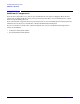
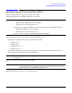
Installing Additional Components Installing Central Processing Units (CPUs) Step 3. Loosen the captive T-15 screws that hold the top cover in place, then grasp the strap handle, raise the cover slightly, and pull the cover toward the front of the server to free the cover tabs from the slots in the chassis. The air baffle will be exposed. Step 4. Loosen the captive T-15 screws on the air baffle. Grasp the two handles on the baffle, and lift the baffle remove it.
Installing Additional Components Installing Central Processing Units (CPUs) Step 5. The following outlines which CPUs and processor support modules are installed for which rp5400 and rp5450 CPU configurations. If installing on an rp5470 proceed to the next step.
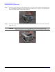
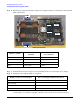
Installing Additional Components Installing Central Processing Units (CPUs) Step 6. The following outlines which CPUs and processor support modules are installed for which rp5470 CPU configurations. PSM 0 CPU 1 CPU 2 CPU 0 CPU 3 PSM 1 L3000 System Board CPU Numbers to be Installed Number of CPUs PSM Numbers to be Installed One 0 0 Two 0 and 2 0 Three 0, 1, and 2 0 and 1 Four 0, 1, 2, and 3 0 and 1 Step 7.
Installing Additional Components Installing Central Processing Units (CPUs) Step 9. Replace the air baffle. Tighten the four captive screws to secure the air baffle in place. Step 10. Replace the top cover. Tighten the four captive screws to secure the top cover in place. Step 11. For rack configurations, insert the rp54xx Server back into the rack. Step 12. For deskside enclosure configurations, replace the deskside enclosure cover. Step 13. Plug in and power-up the rp54xx Server. Step 14.
Installing Additional Components Installing Memory Installing Memory Memory Configuration Rules rp54xx Servers have 16 slots (8 DIMM pairs) for memory DIMMs. These slots are numbered 0a/b, 1a/b,... 7a/b. 8 of these slots (4a/b - 7a/b) are disabled on rp5400 Servers. rp5450 Servers can access all slots. rp5400 and rp5450 Servers have DIMM slots located on the System Board. rp5470 Servers install DIMMs using memory carriers. The memory carriers fit into slots on the system Board.
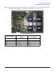
Installing Additional Components Installing Memory Step 6. Refer to the following graphic for memory slot locations. Locate the correct DIMM pair slots. Insert the DIMM connectors into the guides until the card snaps firmly in place. It may be necessary to apply downward force using the palm of your hand on the DIMM. Observe the top of the DIMM to make sure one side is not higher than the other.
Installing Additional Components Installing Memory Installing rp5470 DIMMs Step 1. Power down and unplug the rp54xx Server. NOTE DC voltages are present when the server is connected to AC power. Do not attempt to install or service: CPUs, memory, PSMs, the platform monitor or PCI I/O cards installed in non-turbo slots (1-6) while DC voltage is present. Failure to observe this warning may result in damage to the server. Step 2. Make the top of the server accessible for service. Step 3.
Installing Additional Components Installing Memory a. Locate the memory carrier and pull up on the extractor levers on each end of the memory carrier to unseat the memory carrier from its socket. b. When the memory carrier unseats from the socket, pull it away from the System Board. c. Loosen the captive screws that secure the DIMM Clip and remove the DIMM Clip from the memory carrier. d. Seat the memory DIMM into its socket on the memory carrier. e.
Installing Additional Components Installing Peripheral Component Interconnect (PCI) Cards Installing Peripheral Component Interconnect (PCI) Cards rp54xx Servers have a total of 12 PCI I/O slots. Slots 1 and 2 are reserved for the LAN/SCSI and GSP Core I/O cards, leaving 10 PCI I/O slots available for twin use. rp5400/rp5450 PCI Card Slots For rp5400 and rp5450 models, 10 PCI I/O slots consist of turbo and non-turbo slots. Server PCI slots are shown below.
Installing Additional Components Installing Peripheral Component Interconnect (PCI) Cards rp5470 PCI Card Slots For rp5470 models, the 10 PCI I/O slots consist of twin turbo, turbo, and non-turbo slots. The following illustration shows the PCI card slot layout. • Slots 1 and 2 are reserved for the rp54xx LAN/SCSI and GSP (Guardian Service Processor) Core I/O cards, respectively. Slots 1 and 2 are non-turbo slots. Non-turbo slots share a single 250MB/s PCI bus and are incapable of hot-plug functionality.
Installing Additional Components Installing Peripheral Component Interconnect (PCI) Cards PCI I/O Card Installation Restrictions Restrictions apply regarding the installation of PCI I/O cards which contain a PCI-to-PCI bridge: • HP-UX boot is currently not supported for cards which contain a PCI-to-PCI bridge. • HP-UX patches are required when more than one card containing a PCI-to-PCI bridge is installed in non-turbo slots.
Installing Additional Components Installing Peripheral Component Interconnect (PCI) Cards Product Number Description (all are PCI cards) Max Boot Load Order * Part Number J3525A Dual Port Synchronous Adapter 10 No 19 J3525-60001 J3593A 64 port Serial MUX system card 10 No 20 J3593-60001 J3592A 8 Port PCI Serial MUX card 4 No 21 J3592-60101 A6150A Graphics, USB Card 1 No 22 A6150-60001 A6150BX Pinnacle 2 Graphics 1 No 1 A6150-60003 A6386A Hyper Fabric 2 Interconnect 10
Installing Additional Components Installing Peripheral Component Interconnect (PCI) Cards Installing a PCI Card Follow these procedures to install a PCI card. Step 1. Power down and unplug the rp54xx Server. DC voltages are present when the server is connected to AC power. Do not attempt to install or service: CPUs, memory, PSMs, the platform monitor or PCI I/O cards installed in non-turbo slots (1-6) while DC voltage is present. Failure to observe this warning may result in damage to the server.
Installing Additional Components Installing Peripheral Component Interconnect (PCI) Cards Step 4. Remove the PCI slot cover from the slot that will receive the PCI card. To remove the PCI slot cover, slide the PCI slot cover away from the server. Step 5. Slide the PCI card connectors into the slot, snapping firmly in place. For full length (cards that extend to the left side card guides) PCI cards, use the UPPER card guide. Step 6.
Installing Additional Components Installing Peripheral Component Interconnect (PCI) Cards Step 9. For deskside enclosure configurations, replace the deskside enclosure cover. Step 10. Power the server on. Step 11. Use the server firmware in io command to verify the PCI cards are recognized by the server. If AUTOBOOT is ON, it will be necessary to interrupt the boot process to get to the server firmware Main Menu: Enter command or menu > prompt. Step 12.
Installing Additional Components Installing Graphics Installing Graphics This section explains how to install rp54xx 2D graphics hardware. For a complete graphics solution, three products are required. The products listed below are the only products supported on rp54xx Servers.
Installing Additional Components Installing Graphics rp54xx Servers have a total of 12 PCI I/O slots. Slots 1 and 2 are reserved for the LAN/SCSI and GSP Core I/O cards, leaving 10 PCI I/O slots available for twin use. These 10 PCI I/O slots consist of turbo and non-turbo slots. rp54xx PCI Slots • Slots 1 and 2 are reserved for the rp54xx LAN/SCSI and GSP (Guardian Service Processor) Core I/O cards, respectively. Slots 1 and 2 are non-turbo slots. Non-turbo slots share a single 250MB/s PCI bus.
Installing Additional Components Installing Graphics NOTE DC voltages are present when the server is connected to AC power. Do not attempt to install or service: CPUs, memory, PSMs, the platform monitor or PCI I/O cards installed in non-turbo slots (1-6) while DC voltage is present. Failure to observe this warning may result in damage to the server. Step 3. Make the right side of the server accessible for service.
Installing Additional Components Installing Graphics Step 4. Using a torx 15 screwdriver, loosen the captive screws on the right side panel. This panel has a label which shows which PCI I/O slots are available and the corresponding paths. The label shown below is for an rp5400. Step 5. Grasp the handle on the right rear panel and remove the panel from the side of the chassis. The 12 PCI slots, numbered 1-12 from bottom to top, will be in view.
Installing Additional Components Installing Graphics Step 6. Remove the PCI slot cover from the slot that will receive the PCI card. To remove the PCI slot cover, slide the PCI slot cover away from the server. Step 7. Center the graphics card within the space created by removing the PCI I/O slot cover. Slide the card toward the edge connectors. Ensure the edge connectors on the card are in alignment with the connectors of the slot. Apply pressure to the card until it snaps firmly in place.
Installing Additional Components Installing Graphics NOTE The graphics card must be installed in any turbo slot while the USB will work in any slot. To reserve turbo slots for high performance I/O cards, install the USB card in a non-turbo slot Step 8. At the rear of the chassis, connect the keyboard and mouse cables to the USB card. It does not matter which connector is used for the keyboard or mouse.
Installing Additional Components Installing Graphics Step 9. Connect one end of the 15-pin video cable connector on the graphics card. This connector is labeled “Graphics Display” and “Video Out”. Connect the other end of this cable to the graphics monitor. Step 10. Replace the right side panel and tighten the captive screws. Step 11. For rack configurations, insert the rp54xx Server back into the rack. Step 12. For deskside enclosure configurations, repalce the deskside enclosure cover. Step 13.
Installing Additional Components Installing Graphics Step 14. Use the server firmware in io command to verify the graphics cards are recognized by the server. If AUTOBOOT is ON, it will be necessary to interrupt the boot process to get to the server firmware Main Menu: Enter command or menu > prompt. Step 15. Boot HP-UX and run the ioscan utility to verify the system recognizes the new PCI card. Step 16. Logon as root and install X/CDE/Motif if not already installed.
Installing Additional Components Installing Disk Drives Installing Disk Drives rp54xx Servers support up to four optional internal hard drives. These drives must be installed in the following sequence: It is not necessary to shutdown the HP-UX operating system or power off the server to install a new disk. Follow this procedure to add internal hard disk drives to your rp54xx Server. Step 1. If a front bezel is installed on the face of the server, open the right-hand panel to gain access to the disk slots.
Installing Additional Components Installing Disk Drives Step 3. Insert the new disk drive into the slot until the rear connectors snap into place in the card guide. As shown in the following graphic, the notches at the top of the disk drives must snap over the small brackets in the disk bay to ensure a firm connection. Step 4. Secure the connection by pushing the blue release lever closed. Step 5. Refer to HP-UX documentation to configure the new disk.
2 Server Unpacking and Installation Chapter 2 33
Server Unpacking and Installation Factory Integrated rp54xx Cabinet Installation Factory Integrated rp54xx Cabinet Installation A factory integrated server is one in which the rp54xx Server and associated components are pre-assembled and shipped from the factory already installed in a Hewlett-Packard E-Series cabinet. Factory integrated systems reduce the amount of time required to set-up and begin server operation. 1. Carefully remove the carton and anti-static bag from the pallet. 2.
Server Unpacking and Installation Factory Integrated rp54xx Cabinet Installation 3. At the rear of the cabinet: a. Open the door. b. Remove the anti-tip foot by removing and retaining the two (2) 1/2-inch bolts. Bolts c. For Shipping: L-brackets are mounted behind anti-tip foot. Same bolts secure both. Remove the two (2) L-brackets (revealed by removing the anti-tip foot). 4. Remove the two ramps from the pallet and carefully place them into the slots at the front of the pallet.
Server Unpacking and Installation Factory Integrated rp54xx Cabinet Installation 5. Straighten the rollers on the cabinet base, if needed, and carefully roll it down the ramps. WARNING After removing the server from the pallet, Do not move the cabinet unless the anti-tip feet are installed! The cabinet can tip if care is not used. Due to their low ground clearance the feet may catch on irregularities on the floor, thresholds, or ramps. Do not move the cabinet without first installing the anti-tip feet.
Server Unpacking and Installation Receive and Unpack A Non-Integrated Server Receive and Unpack A Non-Integrated Server WARNING The typical rp54xx system can weigh up to 68kg (150lbs). HP recommends using an an approved lifting device. Lift and move the server in accordance with all local safety regulations. Failure to follow this precaution can cause injury to personnel or damage to equipment.
Server Unpacking and Installation Receive and Unpack A Non-Integrated Server Step 2. If you are moving the server manually, use three people to lift the server from the packing material and pallet. Carefully move the server to the selected location. Step 3. If you are moving the server by an approved lifting device (such as Genie Lift Ô), remove the tear flap from the front lip of the carton bottom to allow access to the server, as illustrated below.
Server Unpacking and Installation Receive and Unpack A Non-Integrated Server Step 5. Raise the lifting device platform enough for the server to clear the pallet and packing materials, as show below.
Server Unpacking and Installation Install Deskside Server Install Deskside Server The following section describes the installation of a server into a Deskside enclosure for installation in an office environment. WARNING The typical rp54xx system can weigh up to 68kg (150lbs). HP recommends using an approved lifting device. • Lift and move the server in accordance with all local safety regulations. • Do not attempt to lift the server by the plastic handles on the top and side covers.
Server Unpacking and Installation Install Deskside Server Ensure that the positioning spring pins in the enclosure base align with the alignment holes in the bottom of the server. NOTE Alignment Spring Pins Captive Fastener Step 3. Position the server on the wheeled enclosure base. Step 4. Tighten the two captive screws in the enclosure base to secure the server to the base. Step 5. Position the enclosure cover (outside skin) over the server and install and tighten the screws to secure it to the base.
Server Unpacking and Installation Install Deskside Server Step 7. Locate the two pull-tabs. One pull-tab is longer than the other. The shorter pull-tab is blank on both sides. The back of the shorter pull-tab provides a writable surface for twin use. Step 8. Locate the plastic bag containing the label sheet (taped to the server). Step 9. Remove the label containing serial number, base product, processor product, and model information from the label sheet and apply to the back of the longer pull-tab.
Server Unpacking and Installation Install Stand-Alone Server in a Cabinet Install Stand-Alone Server in a Cabinet The following describes how to install the A5556A slide-tray assembly into an approved HP cabinet in preparation for installing an rp54xx Server. This slide-tray assembly can be installed in an HP E-Series cabinet or other HP cabinets approved for rp54xx system installation. To install the A5556A slide-tray assembly in an approved HP equipment cabinet, proceed as follows: Step 1.
Server Unpacking and Installation Install Stand-Alone Server in a Cabinet Step 3. On the front vertical mounting posts only, slide M5 sheet metal nuts onto the posts over the holes immediately adjacent to the vertical slots determined in the previous step. Also place M5 sheet metal nuts on the holes directly above these. Orient the sheet metal nuts so that the threaded portion faces towards the outside of the cabinet. There should now be a total of four (4) sheet metal nuts installed. Step 4.
Server Unpacking and Installation Install Stand-Alone Server in a Cabinet Step 7. Take the left hand slide/bracket assembly (marked 337079-1L) and install it into the left hand vertical mounting posts. This is done by inserting the pin at the rear of the slide's mounting bracket into the 23rd hole in the rear vertical mounting post and inserting the hook at the front of the bracket into the vertical, rectangular slot in the aluminum spacer.
Server Unpacking and Installation Install Stand-Alone Server in a Cabinet Step 10. Use an M5 x 30 screw with a cress cup washer to attach the front of the slide to the vertical mounting post. Insert the screw through the slide, through the center hole of the aluminum spacer, through the vertical mounting post, and tighten into the sheet metal nut located at that position. Step 11.
Server Unpacking and Installation Install Stand-Alone Server in a Cabinet Step 13. Use six, M5 x 12 screws (without washers) to attach the tray to the slides. Three screws are used to attach each slide. Insert the screws through the slides, through the tray and tighten into the threaded nuts located on the inside of the sides of the tray. 3 Pan Head M5x12 T25 screws on each side Step 14. From the bottom of the tray pull the plunger pin down and give it a 1/4 turn to hold it in place. Step 15.
Server Unpacking and Installation Stationary L-Bracket Rail Assembly Stationary L-Bracket Rail Assembly rp54xx Servers may be installed into E-Series and approved Non- E-Series cabinets using stationary L-bracket rail assembly kits listed below. NOTE rp54xx Servers are supported in Hewlett-Packard E-series and approved Non- E-series Hewlett-Packard cabinets, and approved rail kits.
Server Unpacking and Installation Stationary L-Bracket Rail Assembly Identifying E-Series HP Cabinets E-Series cabinets have light gray frames, sectioned, plastic outside “skins”, a full return flange, and does not require the installation of the aluminum spacer block supplied, with the rail kits. E-Series cabinets include the following product numbers: A5134A, A5136A, A5136A, A4900A, A4901A, A4902A, J1500A, J1502A, and J1502A.
Server Unpacking and Installation Stationary L-Bracket Rail Assembly • Ensure that the rails extend out from the cabinet posts sufficiently to properly and safely support the equipment being installed. To install an rp54xx Server on stationary rails in an approved cabinet proceed as follows: Step 1. Locate the rail mounting height in the cabinet. Allow for the following space requirements: • For each rp54xx Server, allow 31.8cm (12.5 inches) vertically (7 EIAs or Rack Units (RUs).
3 Cabling and Power-Up Chapter 3 51
Cabling and Power-Up Core I/O Connections Core I/O Connections The following paragraphs describe the indicators and connections of the rp54xx Core I/O. Core I/O consists of a LAN/SCSI card in slot 1 (lower slot in graphic) and a Guardian Service Processor (GSP) in slot 2 (upper slot in graphic). There are two versions of GSP, revision A and revision B. Revision A GSP The following graphic shows the indicators and connectors for the revision A GSP and LAN/SCSI Core I/O boards.
Cabling and Power-Up Core I/O Connections Requires an A5191-63001 “W” adapter cable 5. 10/100 Base-T = Primary LAN (RJ-45) Connection Path 0/0/0/0 6. Green/Yellow (Upper LED) Green = 100 Base-T Mode Green Blinking = 100 Base-T Receiving Amber = 10 Base-T Mode Amber Blinking = 10 Base-T Receiving 7. Green (Lower LED) Green = Link OK (10/100 Base-T Mode indicated by LED #6) Green Blinking = Transmitting 8. Ultra-2 SCSI Connector (68-Pin VHDCI SCSI) Path 0/0/1/0 9.
Cabling and Power-Up Core I/O Connections Revision B GSP The following graphic shows the indicators and connectors for the revision B GSP and LAN/SCSI Core I/O boards. 1 4 2&3 5 6&7 8 9 & 10 1. 10/100-Base-T LAN (RJ-45) Connector. GSP LAN. 2. Green/Red (Upper LED). Green = GSP Power On. Red = Guardian Support Processor Test Failed. 3. Green/Yellow, (Lower LED). Green = 100 Base-T Link OK. Flashing Green = 100 Base-T LAN Activity. Yellow = 10 Base-T Link OK. Flashing Yellow = 10 Base -T LAN Activity.
Cabling and Power-Up Core I/O Connections Green Blinking = 100 Base-T Receiving. Amber = 10 Base-T Mode. Amber Blinking = 10 Base-T Receiving. 7. Green (Lower LED). Green = Link OK (10/100 Base-T Mode indicated by LED #6). Green Blinking = Transmitting. 8. Ultra-2 SCSI Connector (68-Pin VHDCI SCSI). Path 0/0/1/0. 9. SCSI Mode (Green, Upper LED) On = Low Voltage Differential (LVD) Mode. Off = Single Ended Mode. 10.
Cabling and Power-Up Guardian Service Processor (GSP) Overview Guardian Service Processor (GSP) Overview This section provides an overview of the Guardian Service Processor (GSP). The GSP is an always on, dedicated service processor that monitors system power, cooling and configuration, and provides console communications. Power and cooling information is obtained via an interface to the platform monitor card. Configuration information is obtained via connection to the Serial Presence Detect (SPD) bus.
Cabling and Power-Up Guardian Service Processor (GSP) Overview • 10/100 Base-T LAN connector for revision B GSP • On-board processor dedicated to GSP functions • Error logging and notification • Display of system alerts and selftest chassis codes • Powered by 15 VDC housekeeping power that is present when the front panel switch is off • Power and configuration monitoring • RS-232, LAN, REMOTE and WEB console access • Administrator and user security • Alphanumeric paging.
Cabling and Power-Up Configure System Consoles Configure System Consoles rp54xx Servers provide RS-232, REMOTE, LAN and WEB console access. All console access involves the Guardian Service Processor (GSP). rp54xx Servers use either a revision A or revision B GSP. Below is an illustration of the console access provided by the revision A GSP.
Cabling and Power-Up Configure System Consoles The revision B GSP has embedded web access, eliminating the need for an external Secure Web Console (SWC). Below is an illustration of the console access provided by the revision A GSP. GSP Cables Both the revision A and B GSPs provide a DB-25 connector for RS-232 communications. Connect the A5191-63001 W- cable to the revision A GSP DB25 connector or connect the A6144-63001 M-cable to the revision B GSP DB25 connector.
Cabling and Power-Up Configure System Consoles Step 1. The GSP is located in slot 2 of the rp54xx’ rear card cage. Connect the 25-pin end of: • the A5191-63001 W-cable to the 25-pin connector on the revision A GSP card (A5191-60012) OR • the A6144-63001 M-cable to the 25-pin connector on the revision B GSP card (A6144-60012) Step 2. Connect the 9-pin “Console” connector of either the W or M-cable to the 9-pin D-type connector of a 24542G RS-232 cable. Step 3.
Cabling and Power-Up Configure System Consoles HP 700 Series System Console Configuration The following describes the steps required to configure the HP 700 series terminal for VT-100 mode for operation with an rp54xx Server. Although any terminal capable of operating in VT-100 mode can be used, the HP700 series terminal is used here as an example because it is fairly common and it’s configuration is typical of many terminals currently in use.
Cabling and Power-Up Configure System Consoles Local Console Serial Port bit rate: 9600 bits/s Local Console Serial Port Flow Control: Software Local Console Serial Port Terminal Type: vt100 Remote Console Serial Port Modem Protocol: CCITT Remote Console Serial Port Modem bit rate: 19200 bits/s Remote Console Serial Port Modem Flow Control: Software Remote Console Serial Port Modem Transmit Configuration Strings: Enabled Remote Console Serial Port Modem Presence: always connected Do you want to modify th
Cabling and Power-Up Configure System Consoles Configure Remote Console The remote console allows console access via modem connections. Below is an illustration of the REMOTE console. The GSP>ca command is used to configure asynchronous settings for the REMOTE console. Baud rates and emulations should match between the modems, remote ASCII terminal and the GSP. Refer to, “Configure RS232 Console” for information about setting these values.
Cabling and Power-Up Configure System Consoles Configure the LAN Console The LAN console allows you to access the console from the LAN using TelNet or http (revision B GSP only) protocols. Below is an illustration of the LAN console. The configuration of the LAN console of both the revision A and B GSPs may be done from either an ASCII console or the external Secure Web Console. For the revision B GSP, an IP may be assigned via LAN by pinging the LAN from a PC or workstation.
Cabling and Power-Up Configure System Consoles The lc command will start a series of prompts. Respond to each prompt with the appropriate information. Example 3-2 LC command Leaving Console Mode - you may lose write access. When Console Mode returns, type ^E cf to get console write access. GSP Host Name: fesrhapgsp GSP> lc LC This command allows you to modify the LAN configuration. Current configuration: MAC Address: 0x00306e050a63 IP Address: 15.8.133.185 GSP Host Name: fesrhapgsp Subnet Mask: 255.255.
Cabling and Power-Up Configure System Consoles The GSP must be on the same subnet as the system being used to remotely configure the LAN port. If it is not, the remote configuration will be unsuccessful. NOTE Step 1. Determine the MAC address of the revision B GSP by examining the GSP MAC address label on the rear of the server. Step 2. Use the route add command to add the I.P address of the GSP and remote system to the router. Step 3.
Cabling and Power-Up Configure System Consoles Refer to, “Install a Secure Web Console” for more information on Secure Web Console installation and configuration. For the revision B GSP, the web console is an embedded feature. The steps to configure a web console are the same as configuring a LAN console. Refer to, “Configure the LAN Console.” Once the LAN has been configured, access the web console by pointing a web browser, on the same subnet, to the IP of the GSP LAN.
Cabling and Power-Up Configure System Consoles Two browser windows will appear: a window with a white background and the HP invent logo and a separate GSP window with a black background. Example 3-4 GSP Browser Window Use the SETTINGS menu bar to configure web browser emulation. The GSP window also has its own HELP facility.
Cabling and Power-Up Configure System Consoles Example 3-5 GSP Web Browser Help Screen When the separate GSP window is closed, it appears in the HP invent window with Zoom In/Out above it. Click on the Zoom In/Out bar to generate a separate GSP window.
Cabling and Power-Up Configure System Consoles Example 3-6 Combined GSP Browser Window There is not a separate administration “layer” when using the embedded web access of the revision B GSP. Web console access via the external Secure Web Console required that you first logon to the SWC, then click on ACCESS CONSOLE. User configuration was also performed at the Secure Web Console. However, the revision B GSP web console does not require this additional step.
Cabling and Power-Up Secure Web Console Installation Secure Web Console Installation The following section describes installation of the HP Secure Web Console on inside of the rear door of a rack-mounted rp54xx Server. For technical, installation, and configuration instructions for the Secure Web Console, refer to the following URLs on the Internet: General information: http://www.hp.com/ Documentation: http://www.docs.hp.
Cabling and Power-Up Secure Web Console Installation Place the Secure Web Console power supply into the bottom portion of the wire mounting bracket as shown. Step 2. Connect one end of the power cable to the power supply where indicated. Step 3. Position the Secure Web Console unit in the mounting bracket. Step 4. Connect the DC out cable from the power supply to the Secure Web Console. Step 5. Connect one end of the AC power cord (supplied) to the Secure Web Console power supply. Step 6.
Cabling and Power-Up Secure Web Console Installation Step 7. Connect the 9-pin end of the RS-232 cable (Supplied) to the connector labeled CONSOLE on the A5591-63002 “W-type” adapter cable. CAUTION To prevent unauthorized access to your rp54xx system, do not connect the other end of the serial cable to the Secure Web Console until both the server and the Web Console have both been fully configured. Step 8. Connect one end of a LAN cable to RJ-45 connector labeled 10-Base-T on the Secure Web Console.
Cabling and Power-Up GSP Configurable Parameters GSP Configurable Parameters Once a system console is configured, additional GSP parameters may be set. For a complete list use the GSP>he command to access the on-line help facility. Examples of three configurable parameters follow. Adding Users The GSP provides a maximum of 20 users (one administrator and 19 operators). By design, the first user added to the GSP becomes the GSP administrator.
Cabling and Power-Up GSP Configurable Parameters CAUTION Be sure to read each prompt carefully and enter the correct response. A missed or incorrect entry could deny entry to that user. The following is an example of an added user’s information: . . . . . . User’s Name: Joe Smith Organization’s Name: IT Support Dial-back configuration: Disabled Access Level: Operator Mode: multiple User’s state: enabled For the number 1 user, the Access level is administrator.
Cabling and Power-Up GSP Configurable Parameters Return the GSP to Default Configurations The Default Configuration (dc) command is used to reset all or some of the GSP values to the default values. To return GSP values to default configurations, perform the following steps: 1. Access the GSP with the ctrl+b entry. 2. At the GSP prompt, enter the Default Configuration (dc) command: GSP> dc 3. Follow the prompts for the dc command, and be sure to have the change information available.
Cabling and Power-Up rp54xx Server Boot Process rp54xx Server Boot Process The length of time an rp54xx Server will require to complete the boot process depends on the number of processors and the amount of RAM installed. Average configurations can take more than 20 minutes.
Cabling and Power-Up rp54xx Server Boot Process During the Boot process a variety of errors or problems can occur as shown below: 78 Chapter 3
Cabling and Power-Up rp54xx Server Boot Process Initial Power-up The following section describes the process of applying power to the rp54xx Server and booting the system to the UNIX Login prompt. The amount of time it takes to go through self-test then boot the system will vary widely depending on hardware configuration. The following provides a “typical” procedure. Yours may vary depending on software and hardware installed: Step 1. Apply AC Power to the system console. Step 2.
Cabling and Power-Up rp54xx Server Boot Process Step 3. Several self-test boot progress screens will be displayed and will scroll rapidly up the screen. Some tests may pause for up to one minute while the test completes. The following examples of the forward progress screens are typical of the screens displayed.
Cabling and Power-Up rp54xx Server Boot Process Step 4. When the initial power-up boot process completes in approximately one to five minutes, the BCH main menu will be displayed: Step 5. To start the boot process using the primary boot path, enter BO PRI, at Boot Console Handler BCH main menu prompt and press ENTER. NOTE Booting a system to a UNIX login prompt from BCH main menu can take 20 minutes or longer depending on your software and hardware configuration. Step 6.
Cabling and Power-Up rp54xx Server Boot Process 82 Chapter 3
Index A Adding Users, 74 Additional Components, 6 C Configure Remote Console, 63 Configure RS-232 Console, 59 Configure System Consoles, 58 Configure the LAN Console, 64 Configure the Web Console, 66 Configuring the GSP LAN Port via an ASCII console, rp54xx Server Boot Process, 77 S Secure Web Console Installation, 71 Stationary L-Bracket Rail Assembly, 48 U Unpacking the SPU, 37 64 Core I/O Connections, 52 G Graphics Troubleshooting, 30 GSP Cables, 59 GSP Configurable Parameters, 74 GSP Features, 56 GSP
Index 84