Wheel Kit Installation Guide HP Server rp74XX and rx76XX Second Edition Manufacturing Part Number : A9903-96001 July 2003
Notice Copyright 1979-2003 Hewlett-Packard Development Company, L.P. All Rights Reserved. Reproduction, adaptation, or translation without prior written permission is prohibited, except as allowed under the copyright laws. The information contained in this document is subject to change without notice. Hewlett-Packard makes no warranty of any kind with regard to this material, including, but not limited to, the implied warranties of merchantability and fitness for a particular purpose.
1 Wheel Kit Installation Guide The HP Servers rp74XX and rx76XX can be configured as a standalone server. This is accomplished by using the wheel kit in conjunction with the proper tools to attach the wheel kit to the server before rolling it off of the shipping pallet. This guide describes how to install the wheel kit.
Wheel Kit Installation Guide Wheel Kit Installation Wheel Kit Installation NOTE Wheel kits are available in both dark and light colors. Compare the packing list with the contents of the wheel kit before beginning the installation.
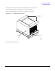
Wheel Kit Installation Guide Wheel Kit Installation 1. Cut and remove the polystrap bands securing the HP Server to the pallet. 2. Lift the carton top from the cardboard tray resting on the pallet. 3. Remove the Wheel Kit carton and the top cushions from the pallet. Figure 1-1 Component Locations Top Cushions Bezel Kit Cardboard Tray MWK001 3/10/03 4. Unfold bottom cardboard tray.
Wheel Kit Installation Guide Wheel Kit Installation 5. Carefully tilt the server and place one of the foam blocks (A6093-44002) under the left side of the server. Do not remove any other cushions until instructed to do so.
Wheel Kit Installation Guide Wheel Kit Installation 6. Carefully tilt the server and place the other foam block provided in the kit under the right side of the server.
Wheel Kit Installation Guide Wheel Kit Installation 7. Remove the cushions from the lower front and rear of the server. Do not disturb the side cushions. Figure 1-4 Remove lower front and rear foam blocks MWK004 3/12/03 8. Locate and identify the caster assemblies.
Wheel Kit Installation Guide Wheel Kit Installation 9. Locate and remove one of the four screws from the plastic pouch. Attach the a caster to the server. Figure 1-5 Attaching a Caster to the Server MWK005 3/12/03 10. Attach the remaining casters to the server using screws supplied in the plastic pouch. 11. Remove the foam blocks from the left and right side of the server. 12. Locate the plywood ramp. 13. Attach the ramp to the edge of the pallet. NOTE There are two pre-drilled holes in the ramp.
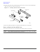
Wheel Kit Installation Guide Wheel Kit Installation 16. Insert the slot on the caster cover into the front caster. Secure the cover to the server by tightening the captive screw on the cover at the rear of the server. Figure 1-6 Securing each Caster Cover to the Server Caster Cover Rear Casters Front Casters Caster Cover MWK006 3/11/03 17. Remove the existing top and side covers and replace them with the new covers provided.
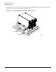
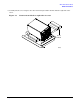
Wheel Kit Installation Guide Wheel Kit Installation Top Cover Replacement Figure 1-7 Top Cover Removing the Top Cover Figure 1-8 Top Cover Retaining Screws Step 1. Loosen the retaining screws securing the cover to the rear of the chassis.
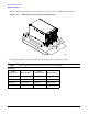
Wheel Kit Installation Guide Wheel Kit Installation Step 2. Slide the cover toward the rear of the chassis. Step 3. Lift the cover up and away from the chassis. Installing the New Top Cover Step 1. Slide the new cover into position. It should easily slide into position; however, a slow firm pressure will be needed to properly seat the cover. Step 2. Tighten the retaining screws securing the cover to the chassis. Removing a Side Cover Figure 1-9 Side Cover Retaining Screw Step 1.
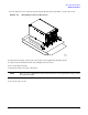
Wheel Kit Installation Guide Wheel Kit Installation Step 2. Slide the cover from the chassis. Figure 1-10 Side Cover Removal Detail Installing a New Side Cover Step 1. Slide the new cover in position. Step 2. The cover easily slides into position; however, a slow firm pressure will be needed to properly seat the cover.
Wheel Kit Installation Guide Wheel Kit Installation Step 3. Tighten the retaining screw securing the cover to the chassis.