
Designing Disaster Recovery Clusters using Metroclusters and Continentalclusters, Reprinted October 2011 (5900-1881)

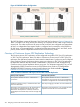
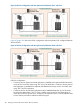


An example for data being replicated in Multi-Hop topology when the application is running at
Site2 is shown in Figure 67 (page 418).
Figure 67 Multi-Hop Topology when the application is running at Site2
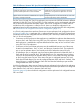
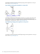
In Multi-Target configuration, the data enters the configuration on a specific node and then splits
into two directions. One direction is the replication to one site and the other direction is the
replication to the another site. An example for data being replicated in Multi-Target topology when
the application is running at Site1 is shown in Figure 68 (page 418).
Figure 68 Multi-Target Topology when the application is running at Site1
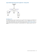
An example for data being replicated in Multi-Target topology when the application is running at
Site2 is shown in Figure 69 (page 419)
418 Designing a Three Data Center Disaster Recovery Solution