Compaq Smart Array 5300 Controller User Guide Part Number 135606-004 May 2002 (Fourth Edition) COMPAQ CONFIDENTIAL Writer: John Turner File Name: a-frnt.
© 2002 Compaq Information Technologies Group, L.P. Compaq, the Compaq logo, Compaq Insight Manager, ProLiant, ROMPaq, SmartStart, SoftPaq, and StorageWorks are trademarks of Compaq Information Technologies Group, L.P. in the U.S. and/or other countries. Microsoft, MS-DOS, Windows, and Windows NT are trademarks of Microsoft Corporation in the U.S. and/or other countries. All other product names mentioned herein may be trademarks of their respective companies.
Contents About This Guide Important Safety Information ............................................................................................ ix Symbols on Equipment...................................................................................................... ix Symbols in Text.................................................................................................................. x Text Conventions.......................................................................................
Contents Chapter 3 Installing the Hardware Preparing the Server........................................................................................................ 3-1 Installing the Smart Array Controller.............................................................................. 3-2 Connecting the Cables..................................................................................................... 3-3 Internal Cabling for Compaq Servers ........................................................
Contents Typical Manual Configuration Procedures in ACU................................................7-16 Using CPQONLIN.........................................................................................................7-26 Running CPQONLIN..............................................................................................7-27 Typical Manual Configuration Procedures in CPQONLIN ....................................
Contents Appendix B Electrostatic Discharge Appendix C Controller Specifications Appendix D Drive Arrays and Fault Tolerance What Is a Drive Array? ...................................................................................................D-1 Fault-Tolerance Methods ................................................................................................D-5 RAID 0—No Fault Tolerance ..................................................................................
Contents Appendix F Probability of Logical Drive Failure Appendix G POST Error Messages Appendix H Questions and Answers Glossary Index Compaq Smart Array 5300 Controller User Guide COMPAQ CONFIDENTIAL Writer: John Turner File Name: a-frnt.
About This Guide This guide provides step-by-step instructions for installation, and reference information for operation, troubleshooting, and future upgrades for the Compaq Smart Array 5300 Controller. Important Safety Information Before installing this product, read the Important Safety Information document provided.
About This Guide This symbol indicates the presence of electric shock hazards. The area contains no user or field serviceable parts. Do not open for any reason. WARNING: To reduce the risk of injury from electric shock hazards, do not open this enclosure This symbol on an RJ-45 receptacle indicates a network interface connection. WARNING: To reduce the risk of electric shock, fire, or damage to the equipment, do not plug telephone or telecommunications connectors into this receptacle.
About This Guide CAUTION: Text set off in this manner indicates that failure to follow directions could result in damage to equipment or loss of information. IMPORTANT: Text set off in this manner presents clarifying information or specific instructions. NOTE: Text set off in this manner presents commentary, sidelights, or interesting points of information. Text Conventions This document uses the following conventions: • Italic type is used for complete titles of published guides or variables.
About This Guide • Compaq ROM-Based Setup Utility User Guide (on the Documentation CD for the server, or downloadable from the Compaq website) Getting Help If you have a problem and have exhausted the information in this guide, you can get further information and other help in the following locations. Compaq Technical Support In North America, call the Compaq Technical Support Phone Center at 1-800-OK-COMPAQ. This service is available 24 hours a day, 7 days a week.
About This Guide Compaq Authorized Reseller For the name of your nearest Compaq authorized reseller: • In the United States, call 1-800-345-1518. • In Canada, call 1-800-263-5868. • Elsewhere, see the Compaq website for locations and telephone numbers. Reader’s Comments Compaq welcomes your comments on this guide. Please send your comments and suggestions by email to ServerDocumentation@compaq.com.
1 Board Components and Features The Compaq Smart Array 5300 Series of controllers comprises two models, the 5302 and the 5304. Model 5302 has two Wide Ultra3 SCSI channels and 128 MB of cache; model 5304 has four Wide Ultra3 SCSI channels and 256 MB of cache. You can upgrade the 5302 model to have four channels, 256 MB of cache, or both, by means of the appropriate option kits.
Board Components and Features NOTE: On both controller models, ports 1 and 2 each have two connectors (one internal and one external). However, only one connector can be used per port at any given time. Ports 3 and 4 (available on the 5304) can be used only for external drives.
Board Components and Features Figure 1-3: Two- to four-channel adapter upgrade option Figure 1-4: Array accelerator cache with batteries For details of the controller board specifications, refer to Appendix C. Compaq Smart Array 5300 Controller User Guide COMPAQ CONFIDENTIAL Writer: John Turner File Name: b-ch1 board components.
Board Components and Features Overview of Controller Features • Two or four Wide Ultra3 SCSI channels, supporting up to 56 drives (4 channels, 14 drives per channel) • Support for Microsoft Windows 2000, Windows NT 4.0, Linux, Novell NetWare 5.
Board Components and Features Overview of Array Accelerator Features The array accelerator is a high performance, battery-backed, 100-MHz SDRAM DIMM cache module. Array controllers use cache to store read data from the hard drives. The system can later access this read data. The controller firmware uses the read-ahead and most recently used caching algorithms. Array controllers also use cache to complete drive write operations more quickly.
Board Components and Features For each of these operations, data has to be reorganized among hard drives, and must be saved to non-volatile storage during the operation. (For further details of these operations, refer to Chapter 7, Appendix D, and Appendix E.) Without batterybacked cache, the data can only be stored at empty locations within the drive array, so these operations cannot occur at all if the array is full.
Board Components and Features Figure 1-5: Battery packs This data protection (and the time limit) also applies if an equipment failure or power outage occurs. When power is restored to the system, an initialization process writes the preserved data to the hard drives. The batteries are continuously recharged using a trickle-charging process whenever the system power is on. Under normal operating conditions, a battery pack lasts for three years before replacement is necessary.
Board Components and Features PCI System Interface Smart Array 5300 controllers interface to the server through a high-performance 64-bit PCI bus that: • Runs at 66 MHz • Provides a high-speed path (up to 528 MB/s) between the system board and the controller • Includes two parity protection signals The Smart Array 5300 Controller is a PCI Bus Master device conforming to Rev. 2.2 of the PCI Local Bus Specification.
Board Components and Features • Auto-Reliability Monitoring (ARM) is a background process that scans hard drives for bad sectors in fault-tolerant logical drives. ARM also verifies the consistency of parity data in logical drives that are using RAID 5 or RAID ADG. This process assures that you can recover all data successfully if a drive failure occurs in the future. ARM operates only when you select a fault-tolerant configuration (RAID 1 or higher).
Board Components and Features • Recovery ROM is a redundancy feature that ensures continuous system availability by providing a backup ROM. This feature protects against corruption of a ROM image (caused, for example, by power fluctuation during ROM upgrade). If corruption occurs, the server automatically restarts using the remaining good copy of the ROM image. When you upgrade the ROM, the inactive image (the one not being used by the system) is upgraded.
2 Installation Overview The details of the steps required to install the controller depend on whether the server has an operating system installed and contains data. The flowcharts in Figure 2-1 and Figure 2-2 summarize the installation procedures for the most common scenarios. Procedure for a New System 1 Install the controller hardware (Chapter 3), if it is not pre-installed. ....... 2 Update the system firmware (Chapter 4). : 3 Update the controller firmware (Chapter 5).
Installation Overview Procedure for a Pre-configured System 1 Back up data (required if migrating from a non-array controller). ----- 2 Update the system firmware (Chapter 4). : 3 If the controller is to be the boot device, install the device driver for your operating system (Chapter 8). Otherwise, continue with step 4. : 5 Set the controller order (Chapter 6). ----- 4 Install the controller hardware (Chapter 3).
3 Installing the Hardware Preparing the Server Before installing the controller in the server, back up all data. This step is mandatory if you are moving non-arrayed SCSI drives to a Smart Array controller, because data is not preserved during a move between array controllers and non-array controllers. WARNING: To reduce the risk of personal injury or damage to the equipment, consult the safety information and user documentation provided with your computer before attempting the installation.
Installing the Hardware 4. Unplug the AC power cord from the outlet, and then from the server. IMPORTANT: If you will be replacing a Smart controller with a Smart Array controller, see the “External Cabling for Compaq Servers” section to determine the external cabling requirements. 5. Disconnect any peripheral devices from the server. WARNING: To reduce the risk of personal injury from hot surfaces, allow the internal system components and hot-plug hard drives to cool before touching them.
Installing the Hardware Figure 3-1: Installing a Smart Array 5300 Controller NOTE: Your server may look slightly different from the one illustrated. 5. Press the controller board firmly into the slot so that the contacts on the board edge are properly seated in the system board connector. 6. Secure the board in place with the hot-plug latch or retaining screw. 7. Continue by following the instructions given in “Connecting the Cables.
Installing the Hardware On Compaq products that support hot-pluggable drives, the SCSI IDs for peripherals are automatically set. For non-hot-pluggable devices, the IDs must be set manually by using switches or jumpers on the device itself. IMPORTANT: When replacing an existing Smart controller with a Smart Array controller without reconfiguring the arrays, all of the drives should be connected exactly as they were on the old controller (port 1 to port 1, controller 1 to controller 1, and so on).
Installing the Hardware The multi-device cable may have been provided with your server. If you need additional cables, order the cable option kit, Part Number 166389-B21. This cable is equipped to terminate either Wide Ultra3 or Wide Ultra2 drives. CAUTION: Cable assembly 148785-001 is included in option kit 166389-B21 and is required with Wide Ultra3 drives. Failure to use this cable may result in reduced performance and/or data loss. For additional information about drive installation, see Appendix E.
Installing the Hardware Table 3-1: External SCSI Cables for Compaq Enclosures Cable Type Length Option Kit Number Cable Assembly Number VHDCI to VHDCI 1.8 m / 6 ft 341174-B21 313374-001 VHDCI to VHDCI 3.6 m / 12 ft 341175-B21 313374-002 VHDCI to VHDCI 7.2 m / 24 ft 164604-B21 313374-004 VHDCI to VHDCI 11.7 m / 39 ft 150214-B21 313374-005 VHDCI to Wide 1.8 m / 6 ft 341176-B21 313375-001 VHDCI to Wide 3.
4 Updating the System Firmware To update the system firmware, the Compaq System ROMPaq TM utility is used. NOTE: This utility is not to be confused with the Options ROMPaq utility (refer to Chapter 5), which is used to update the firmware on server options and SCSI drives.
Updating the System Firmware Running System ROMPaq from Diskette To run System ROMPaq from diskette, you must first create a System ROMPaq diskette from the CD or from the appropriate SoftPaq file. Creating a System ROMPaq Diskette from the CD 1. Insert the SmartStart CD into the CD-ROM drive tray of a server with a bootable CD-ROM drive. 2. Restart the server. 3. On the Compaq System Utilities screen, select Create Support Software. 4.
Updating the System Firmware Using the Diskette 1. With the server powered down, place the System ROMPaq diskette in the diskette drive. 2. Power up the server. 3. When the Welcome screen is displayed, press the Enter key. 4. When the Select A Device screen is displayed, select your server from the list of programmable devices, and then press the Enter key.
5 Updating the Controller Firmware You can update the firmware on Compaq options by using the Options ROMPaq utility. There are two versions of this utility: Options ROMPaq for Array Controllers, and Options ROMPaq for Internal (SCSI Attached) Drives. If you purchased your server with an array controller already installed, you do not need to run this utility during server installation.
Updating the Controller Firmware Running Options ROMPaq from the CD 1. Place the CD in the server CD-ROM drive. 2. Restart the server. 3. When the System Utilities Menu screen is displayed, select Run Options ROMPaq, and then press the Enter key. 4. When the Welcome screen is displayed, press the Enter key. 5. On the Select A Device screen, select All Compaq Smart Array 5300 Controller(s) from the list of programmable devices, and then press the Enter key. 6.
Updating the Controller Firmware 8. When reprogramming of the controller ROM is finished, you can reprogram more options or exit the utility. — To reprogram another Compaq option, press the Enter key, and then repeat steps 5 through 7. — If you have finished reprogramming Compaq options, press the Esc key to exit the utility. 9. Remove the CD and restart the server.
Updating the Controller Firmware 5. Choose Create Diskettes Only and then click Next. 6. Follow the remaining on-screen instructions to create the Options ROMPaq diskettes. 7. To complete the firmware update, follow the procedure given in the section, “Using the Diskettes.” Creating Diskettes Using the SoftPaq File 1. Create a temporary directory on your hard drive. 2. On the Compaq website, locate the page containing the SoftPaq file for the Options ROMPaq utility. 3.
Updating the Controller Firmware 5. If the controller that you want to update the firmware for is on the list of programmable devices, select it and press the Enter key. (If it is not present, you are prompted to insert the remaining diskettes for devices not listed on the first diskette.) 6. The action that you must now take depends on the message on the screen.
Updating the Controller Firmware Updating the System Partition If you are installing the controller on a server that was previously configured with SCU, you must now use this utility to update the system partition. NOTE: If your server uses the ROM-Based Setup Utility (RBSU), you do not need to run SCU. SCU is provided on both the SmartStart CD and the Smart Array Controller Support Software CD. Compare the SCU version numbers from these two sources and use the most recent version.
6 Setting the Controller Order After installing the controller hardware and updating the controller firmware: • Configure the system by using either the ROM-Based Setup Utility (RBSU) or the System Configuration Utility (SCU), following the procedure given in the server user guide. • Set the boot controller by using RBSU or the Option ROM Configuration for Arrays (ORCA) utility (described in this chapter). • Create at least one logical drive by using ORCA or ACU (as described in Chapter 7).
Setting the Controller Order To use RBSU: 1. Power up the server. 2. Press the F9 key when prompted during system startup. The main ROM-Based Setup Utility screen is displayed. Figure 6-1: Main ROM-Based Setup Utility screen 3. Configure your system. (For detailed instructions, refer to the Compaq ROMBased Setup Utility User Guide.) 4. Select Boot Controller Order on the main RBSU screen and follow the onscreen prompts to set the boot controller. 5.
Setting the Controller Order 3. On the Option ROM Configuration for Arrays Main Menu screen, select Select as Boot Controller and follow the prompts to set the boot controller for the system. If you want to use ORCA to create logical drives at this point, you do not need to exit the utility yet. Continue using ORCA as described in Chapter 7. Compaq Smart Array 5300 Controller User Guide COMPAQ CONFIDENTIAL Writer: John Turner File Name: g-ch6 setting the controller order.
7 Configuring an Array Compaq provides four utilities for configuring an array: • Option ROM Configuration for Arrays (ORCA)—a simple ROM-based configuration utility that runs on all operating systems • Array Configuration Utility (ACU)—a versatile configuration utility that provides maximum control over configuration parameters • Array Configuration Utility XE (ACU-XE)—a browser-based version of ACU • NetWare Online Array Configuration Utility (CPQONLIN)—a menu-driven utility for NetWare The follo
Configuring an Array Table 7-1: Comparison of Utilities for Configuring an Array ACU ACU-XE CPQONLIN ORCA Uses a graphical interface + + 0 0 Available in languages other than English + + 0 0 Executable at any time + + + 0 Available on CD + + + 0 Uses a wizard to suggest the optimum configuration for an unconfigured controller + + + 0 Describes configuration errors + + 0 0 Windows 2000 + + 0 + Windows NT + + 0 + NetWare +* +* + + Linux +* + 0 + Creation
Configuring an Array Using ORCA When a computer system is powered up, part of the startup sequence is the Power-On Self-Test (POST). Any array controllers that are in the system are initialized while POST is running. If the array controller supports ORCA, POST temporarily halts and an ORCA prompt message is displayed for about five seconds. (If ORCA is not supported, the prompt message is not displayed and the system continues with the startup sequence.
Configuring an Array NOTE: ORCA allows only one array to use a given online spare. 3. Press the Enter key to accept the settings. 4. Press the F8 key to confirm your settings and save the new configuration. After several seconds, the Configuration Saved screen is displayed. 5. Press the Enter key to continue. You can now create another logical drive by repeating the previous steps. NOTE: Raw logical drives are invisible to the operating system.
Configuring an Array You can view context-sensitive online help for each screen by pressing the F1 key or clicking Help. The status bar at the bottom of the screen also displays messages that describe the current selection. NOTE: Raw logical drives are invisible to the operating system. To make the new logical drives available for data storage, format the logical drive using the instructions given in your operating system documentation.
Configuring an Array Main ACU Screen After the configuration wizard has finished or been bypassed, the screen looks like Figure 7-2. This is the main ACU screen. Figure 7-2: Main ACU screen This screen contains the following regions: • Menu bar • Controller Selection drop-down list • Configuration View window • Drive View box • Controller box • Array box • Logical Drive box • More Information button Some buttons will be grayed out.
Configuring an Array Menu Bar The menu bar at the top of the main ACU screen contains the following drop-down menus: • Controller—Allows you to select a controller, refresh the screen, save or clear a configuration, create an array, or exit the program. Other menu items give access to settings, advanced features, information, and the configuration wizard. • Array—Allows you to delete or modify an array, or to expand array capacity, create logical drives, and view array information.
Configuring an Array Figure 7-4: Physical Configuration View window NOTE: Selecting any item in the configuration view window will cause the corresponding hard drive tray LEDs to blink. This feature is useful for identifying all physical drives in an array or logical drive, all drives on a controller, or a specific physical drive. Drive View Box Select the radio buttons in this box to display a logical or physical configuration view in the configuration view window.
Configuring an Array Array Box The buttons in the Array box are activated when you select an array in the configuration view window. Figure 7-7: Array box Click one of these buttons to display the Modify Drive Array screen, the Expand Array screen, or the Create Logical Drive screen. Logical Drive Box The buttons in the Logical Drive box are activated when you select a logical drive in the configuration view window.
Configuring an Array Secondary Screens Controller Settings Screen To display this screen, click Settings in the Controller box (Figure 7-6) on the main ACU screen. This screen allows you to set the rebuild priority, expand priority, and accelerator read/write ratio. Figure 7-9: Controller Settings screen The settings that you select for Rebuild Priority and Expand Priority will not affect the performance of an idle system.
Configuring an Array NOTE: If you optimize the Accelerator Ratio settings, you may also want to change the Stripe Size setting. For details, refer to the “Create Logical Drive Screen” section, Table 7-2, and Table 7-3. Create Drive Array Screen To display this screen, click Create Array in the Controller box (Figure 7-6) on the main ACU screen.
Configuring an Array When you select a drive in one of the panels, the appropriate buttons become functional. You can select several drives at a time from the same panel, and assign or remove them all simultaneously; in this case, the buttons each show two drives. Also, if spare drives are selected in the right-hand panel, the design on the middle button changes to denote the removal of spare drives. Modify Drive Array Screen To display this screen, click Modify in the Array box on the main ACU screen.
Configuring an Array Figure 7-11: Create Logical Drive screen Three features on this screen merit further description: • Stripe Size box • Logical Drive Size box • Advanced button The Stripe Size box has a drop-down list that lets you select the width of a data stripe. (This width corresponds to the size of a data block on each hard drive in the logical volume, as described in Appendix D).
Configuring an Array Table 7-3: Optimum Stripe Size for a Given Application Type of Server Application Suggested Stripe Size Change Mixed read/write Accept the default value Mainly sequential read (such as audio/video applications) Use larger stripe sizes for best performance Mainly write (such as image manipulation applications) Use smaller stripes for RAID 5 Use larger stripes for RAID 0, RAID 1+0 The Logical Drive Size box shows how much drive capacity is available on the selected logical drive
Configuring an Array Some operating systems need to use the maximum boot size to be able to create large boot partitions. For example, enabling the maximum boot size on a logical drive in the Windows NT 4.0 operating system allows you to create a bootable partition with a maximum size of 8 GB. NOTE: Enabling the maximum boot size may decrease performance of the logical drive. Modify Logical Drive Screen To display this screen, click Modify in the Logical Drive box (Figure 7-8) on the main ACU screen.
Configuring an Array Extend Logical Drive Screen To display this screen, click Extend in the Logical Drive box (Figure 7-8) on the main ACU screen. This screen allows you to increase the capacity of a logical drive while the system is online, without disruption of data. IMPORTANT: Not all operating systems support online capacity extension. For more information, refer to the section “Extending Logical Drive Capacity.
Configuring an Array 3. Create one or more logical drives on the array. For this example, assume that you have ten 9.1-GB drives connected to your controller. You want to make two arrays: • Array A: seven 9.1-GB drives with a spare, configured with RAID 5 fault tolerance • Array B: two 9.1-GB drives in a RAID 1+0 fault-tolerance configuration Configuring the Controller Settings 1. On the main ACU screen, select the controller to be used from the drop-down list in the Controller Selection box.
Configuring an Array 3. Click the Assign Drive to Array button (Figure 7-15) in the middle of the screen. Figure 7-15: Assign Drive to Array button 4. Select the drive at Port 1: SCSI ID 7 and click the Assign Spare to Array button in the lower middle part of the screen. NOTE: You can share any given spare among several arrays. You can also assign several spares to just one array, or share one group of spares among several arrays.
Configuring an Array The Logical Configuration View window now looks like Figure 7-17. Figure 7-17: Logical Configuration View of Example Array 6. Select the controller icon, and then click Create Array to create Array B. 7. Repeat the previous steps to assign both remaining 9.1-GB drives to array B. 8. Click Done to return to the main ACU screen. In this example, each array was created using drives from the same SCSI port.
Configuring an Array 9. Create a logical drive on Array B: a. Select the Array B icon or the Unused Space icon under Array B in the Logical Configuration View window. b. Repeat steps 2 through 7. This time, select RAID 1+0 as the fault-tolerance method in step 3. c. Save the configuration, as in step 8. The main ACU screen now looks like Figure 7-18. Figure 7-18: Example configuration with two arrays NOTE: The capacity shown for each logical drive is the free capacity available for data storage.
Configuring an Array During capacity expansion, ACU automatically redistributes existing logical drives across all of the physical drives in the expanded array. If the array being expanded has more than one logical drive, data is redistributed one logical drive at a time. Newly created logical drives are not available until capacity expansion has finished. CAUTION: Do not exchange the controller or array accelerator board during array capacity expansion.
Configuring an Array Now you install a 9.1-GB drive, and want to expand Array A to include this new drive. This scenario is represented in Figure 7-19. Figure 7-19: Starting an array expansion To expand Array A and create a second logical drive on this array: 1. Select Array A in the Logical Configuration View window. 2. Click Expand in the Array box. 3. In the left-hand panel of the Expand Array A window, select the unassigned 9.1-GB drive. 4.
Configuring an Array Figure 7-20: Create Logical Drives screen 6. Click Create Logical Drive. 7. Set the fault tolerance, stripe size, array accelerator, and size for the second logical drive that you want to create on Array A. 8. Click Done to return to the Create Logical Drives screen. 9. Click Done again to return to the main ACU screen. 10. On the menu bar, select Controller, Save Configuration. The settings for the new logical drive are saved and the capacity expansion process begins.
Configuring an Array The Windows NT 4.0 operating system supports online logical drive capacity extension. Some operating systems also support offline capacity extension. Before extending logical drives, check the operating system documentation for current information, or contact your operating system vendor. NOTE: The extension process takes about 15 minutes per gigabyte.
Configuring an Array 8. Make the extra capacity of the logical drive available to the operating system by one of the following methods: — Create a new partition in the logical drive by using the operating system partitioning software. — Increase the size of an existing partition by using the operating system partitioning software or third-party partitioning tools.
Configuring an Array 5. Click Migrate in the Logical Drive box. 6. Change the RAID level by selecting the appropriate check box. 7. Change the stripe size (Table 7-3 gives the optimum stripe size for specific situations). 8. Click Done to return to the main ACU screen. If you get a message stating that the number of sectors needs to be increased: a. Delete the old logical volume. b. Reconfigure the array as a new logical volume with the new fault-tolerance method and stripe size that you had selected. c.
Configuring an Array Running CPQONLIN 1. Enter cpqonlin at the console prompt. 2. Use the arrow keys to highlight Array Configuration Utility, and then press the Enter key. 3. From the list of controllers that is presented, select the one that you want to configure. — If no logical drives are configured for the controller, the auto-configuration wizard screen (Figure 7-21) is displayed. — If logical drives are present on the controller, the manual configuration screen (Figure 7-22) is displayed.
Configuring an Array 2. Press the Esc key to save the changes and return to the controller selection screen. 3. Restart the system to apply the changes. NOTE: Raw logical drives are invisible to the operating system. To make the new logical drives available for data storage, format the logical drive using the instructions given in your operating system documentation.
Configuring an Array Table 7-4: Menu Options in CPQONLIN CONTROLLER OPTIONS Menu Controller Settings Rebuild Priority Expand Priority Accelerator Ratio Create New Array Create Array Assign Drive Assign Array Remove Drive Accept Changes Physical Drives (Panel shows spare drives and unassigned hard drives attached to the controller) New Array (Panel shows physical view of new array) ARRAY OPTIONS Menu Expand Array Expand Array Assign Drive Accept Changes Assign Spare Physical Drives (Panel show
Configuring an Array Typical Manual Configuration Procedures in CPQONLIN Creating a Custom Configuration for a New Array 1. In the Logical Configuration View panel, highlight the controller that you want to configure and then press the Enter key. 2. Choose Create New Array in the Controller Options panel, and then press the Enter key. The screen now displays three panels: Create Array, Physical Drives, and New Array. 3. Choose Assign Drive in the Create Array panel, and then press the Enter key.
Configuring an Array Adding Spare Drives To add spare drives to an array, the array controller must have at least one attached drive that is either unassigned or is assigned as a spare to another array. You can: • Assign a different online spare to each array on the controller. • Share one online spare among several arrays on the same controller, for efficient use of drive capacity. • Assign several online spares to just one array.
Configuring an Array Configuring the New Logical Drive 1. In the Logical Configuration View panel, highlight the new logical drive that you want to configure, and then press the Enter key. 2. Select Fault Tolerance in the Logical Drive Options menu, and then press the Enter key. 3. Choose the RAID level that you want and then press the Enter key. 4. Choose Stripe Size and then press the Enter key. 5. Choose the stripe size that you want and then press the Enter key. 6.
Configuring an Array 1. In the Logical Configuration View panel, select the controller that you want to configure, and then press the Enter key. 2. Select Controller Settings in the Controller Options panel, and then press the Enter key. The controller settings screen is displayed. Figure 7-23: Controller settings screen 3. Alter the settings on this screen to suit your needs. 4. Press the Esc key to save the new configuration. 5. Exit CPQONLIN, and then restart the system to apply the changes.
Configuring an Array 2. Check that the array accelerator batteries (if present) are fully charged. 3. In the Logical Configuration View panel, select the array that you want to expand, and then press the Enter key. 4. Select Expand in the menu, and then press the Enter key. 5. Select the hard drive that you want to add to the array, and then press the Enter key. IMPORTANT: Do not assign a group of physical drives to the same array unless they are of the same capacity.
Configuring an Array 6. Press the Esc key to accept the changes and begin migration. You can check the progress of the migration at any time by pressing the F3 key and then scrolling to the progress bar near the bottom of the screen. Compaq Smart Array 5300 Controller User Guide COMPAQ CONFIDENTIAL Writer: John Turner File Name: h-ch7 configuring an array.
8 Installing the Device Drivers The drivers for the controller are located on the Smart Array Controller Support Software CD and on the SmartStart CD. Updates are posted to www.compaq.com. Using the Smart Array Controller Support Software CD Instructions for installing the drivers from the Smart Array Controller Support Software CD are given in the leaflet provided with the CD. Note that the exact procedure depends on whether the server is new, or already contains the operating system and user data.
Installing the Device Drivers To create CSPs: 1. Insert the SmartStart CD into the CD-ROM drive tray of a server with a bootable CD-ROM drive. The server does not need to be the one in which you are going to install the controller. 2. Restart the server. 3. On the Compaq System Utilities screen, select Create Support Software. 4. On the Diskette Builder screen, select Create Support Software From CD Only. 5. Scroll down the list and select the support software for the operating system that you are using.
9 Upgrading and Replacing Options Array Accelerator To remove the existing array accelerator board: 1. Squeeze the ends of the heat sink clip inwards (1), and then rotate the clip out of the heat sink (2). 1 2 1 Figure 9-1: Removing the heatsink 2. Lift the heatsink out of the frame. Compaq Smart Array 5300 Controller User Guide COMPAQ CONFIDENTIAL Writer: John Turner File Name: j-ch9 upgrading and replacing options.
Upgrading and Replacing Options 3. Rotate the clip back towards the controller board to allow room for the array accelerator board to be removed. 4. Remove the plastic retainer (1) by detaching it from the array accelerator and unhooking it from the controller board. 1 2 Figure 9-2: Releasing the array accelerator board 5. Swing out the DIMM ejectors (2) on each side of the array accelerator. 6.
Upgrading and Replacing Options Figure 9-3: Unplugging the array accelerator board To install the new array accelerator board: 1. Push the array accelerator board firmly into the DIMM connector socket. 2. Close the DIMM ejector levers to lock the array accelerator into place. 3. Reinstall the plastic retainer. 4. Reattach the heatsink. Installation of the new array accelerator board is complete.
Upgrading and Replacing Options Battery Pack WARNING: There is a risk of explosion, fire, or personal injury if the battery pack is replaced incorrectly or mistreated. To reduce the risk: • Do not attempt to recharge the battery outside of the controller. • Do not expose to water, or to temperatures higher than 60°C (140°F). • Do not abuse, disassemble, crush, puncture, short external contacts, or dispose of in fire or water. • Replace only with the Compaq spare designated for this product.
Upgrading and Replacing Options Figure 9-5: Releasing the battery pack 3. Remove the pack from the array accelerator board. If the battery pack flange grasps the board tightly, rock the pack slightly from side to side while lifting the pack upward. Figure 9-6: Removing the battery pack Since both packs are likely to be discharged at a similar rate, repeat the procedure for the other battery pack.
Upgrading and Replacing Options To install a new NiMH battery pack: 1. Wait about 15 seconds after removing the old battery packs to allow the battery charge monitor to reset. 2. Hook the battery pack flange onto the top of the array accelerator board, with the pack held at a 10-degree angle to the plane of the board. Figure 9-7: Installing the new battery pack 3. Rotate the battery pack towards the array accelerator board.
Upgrading and Replacing Options 1 2 Figure 9-8: Securing the flange and clip Installation of the new battery pack is complete. Repeat for the other battery pack. Compaq Smart Array 5300 Controller User Guide COMPAQ CONFIDENTIAL Writer: John Turner File Name: j-ch9 upgrading and replacing options.
Upgrading and Replacing Options 2- to 4-Channel Adapter Board To remove the existing 2- to 4-channel adapter board: 1. Remove the screw that secures the 2- to 4-channel adapter board. This screw is reachable from the back of the controller board. Figure 9-9: Removing the securing screw 9-8 Compaq Smart Array 5300 Controller User Guide COMPAQ CONFIDENTIAL Writer: John Turner File Name: j-ch9 upgrading and replacing options.
Upgrading and Replacing Options 2. Unplug the 2- to 4-channel adapter board from the connector on the controller board. Figure 9-10: Unplugging the 2- to 4-channel adapter board 3. Pull the 2- to 4-channel adapter board out of the VHDCI socket. Figure 9-11: Removing the 2- to 4-channel adapter board Compaq Smart Array 5300 Controller User Guide COMPAQ CONFIDENTIAL Writer: John Turner File Name: j-ch9 upgrading and replacing options.
Upgrading and Replacing Options To install the new 2- to 4-channel adapter board: 1. Insert the VHDCI connector on the adapter board into the unoccupied VHDCI slot (1) while sliding the adapter board under the bracket lip (2) on the occupied VHDCI slot. 3 2 1 Figure 9-12: Installing the adapter board 2. Plug the adapter board into the connector (3) on the controller board. 3.
Upgrading and Replacing Options Figure 9-13: Securing the adapter board to the array controller board Installation of the new adapter board is complete. Compaq Smart Array 5300 Controller User Guide COMPAQ CONFIDENTIAL Writer: John Turner File Name: j-ch9 upgrading and replacing options.
Upgrading and Replacing Options Enabling RAID ADG You can enable RAID ADG on a Smart Array 5300 Controller by installing a software key. Alternatively, if you have an older version of the controller, you can install a hardware enabler module on the controller board. Using the Software Key 1. Confirm that the array accelerator has a capacity of at least 64 MB. 2. Close all applications and utilities on the server containing the controller. 3.
Upgrading and Replacing Options For further instructions or clarifications regarding the software key installation procedure, refer to the ACU-XE online help. Using the Enabler Module The connector for the RAID ADG Enabler Module is located at the corner of the controller board near the array accelerator connector socket, as shown in Figure 9-14. The module attaches to the controller board with the narrow tab (circled in Figure 9-15) nearest to the corner of the controller board.
Upgrading and Replacing Options Figure 9-15: Aligning the module on the controller board When replacing a Smart Array 5300 Controller, you may want to remove the RAID ADG Enabler Module from the old controller and install it onto the new controller. 9-14 Compaq Smart Array 5300 Controller User Guide COMPAQ CONFIDENTIAL Writer: John Turner File Name: j-ch9 upgrading and replacing options.
Upgrading and Replacing Options To remove the RAID ADG Enabler Module: Press the innermost plastic clip under the controller board towards the other clip (1), and push the module out of the board (2). 1 2 Figure 9-16: Removing the RAID ADG Enabler Module To install the module on the new controller board: 1. Check that the array accelerator on the new controller board has at least 64 MB of read/write cache. 2.
Upgrading and Replacing Options 3. Use one thumb to press the tab at the top of the rear end outward (2a), while using the other thumb to gently press the other end of the module (2b) into the connector and slot on the controller board. 1 2 a b Figure 9-17: Installing the module Installation of the RAID ADG Enabler Module is complete. 9-16 Compaq Smart Array 5300 Controller User Guide COMPAQ CONFIDENTIAL Writer: John Turner File Name: j-ch9 upgrading and replacing options.
A Regulatory Compliance Notices Regulatory Compliance Identification Numbers For the purpose of regulatory compliance certifications and identification, your product has been assigned a unique Compaq series number. The series number can be found on the product nameplate label, along with all required approval markings and information. When requesting compliance information for this product, always refer to this series number.
Regulatory Compliance Notices Class A Equipment This equipment has been tested and found to comply with the limits for a Class A digital device, pursuant to Part 15 of the FCC Rules. These limits are designed to provide reasonable protection against harmful interference when the equipment is operated in a commercial environment.
Regulatory Compliance Notices Declaration of Conformity for Products Marked with the FCC Logo, United States Only This device complies with Part 15 of the FCC Rules. Operation is subject to the following two conditions: (1) this device may not cause harmful interference, and (2) this device must accept any interference received, including interference that may cause undesired operation. For questions regarding your product, contact us by mail or telephone: • Compaq Computer Corporation P. O.
Regulatory Compliance Notices Cables Connections to this device must be made with shielded cables with metallic RFI/EMI connector hoods in order to maintain compliance with FCC Rules and Regulations. Canadian Notice (Avis Canadien) Class A Equipment This Class A digital apparatus meets all requirements of the Canadian Interference-Causing Equipment Regulations Cet appareil numérique de la classe A respecte toutes les exigences du Règlement sur le matériel brouilleur du Canada.
Regulatory Compliance Notices European Union Notice Products with the CE Marking comply with both the EMC Directive (89/336/EEC) and the Low Voltage Directive (73/23/EEC) issued by the Commission of the European Community.
Regulatory Compliance Notices Japanese Notice Taiwanese Notice A-6 Compaq Smart Array 5300 Controller User Guide COMPAQ CONFIDENTIAL Writer: John Turner File Name: k-appa Regulatory Compliance Notices.
Regulatory Compliance Notices Battery Replacement Notice The array accelerator on the controller is equipped with a nickel metal hydride (NiMH) battery pack. Replacement is to be performed by a Compaq authorized service provider using the Compaq spare designated for this product. WARNING: There is a risk of explosion, fire, or personal injury if the battery pack is not properly handled. To reduce the risk: • Do not attempt to recharge the battery outside of the controller.
B Electrostatic Discharge To prevent damaging the system, be aware of the precautions you need to follow when setting up the system or handling parts. A discharge of static electricity from a finger or other conductor may damage system boards or other static-sensitive devices. This type of damage may reduce the life expectancy of the device. To prevent electrostatic damage, observe the following precautions: • Avoid hand contact by transporting and storing products in static-safe containers.
Electrostatic Discharge • Use a portable field service kit with a folding static-dissipating work mat. If you do not have any of the suggested equipment for proper grounding, have a Compaq authorized reseller install the part. NOTE: For more information on static electricity, or assistance with product installation, contact your Compaq authorized reseller. B-2 Compaq Smart Array 5300 Controller User Guide COMPAQ CONFIDENTIAL Writer: John Turner File Name: l-appb Electrostatic Discharge.
C Controller Specifications Table C-1: Controller Specifications Dimensions 31.5 cm × 10.8 cm × 1.5 cm (12.4 in × 4.3 in × 0.6 in) Power required 21.2 W for 5302 (16.3 W at 3.3 V, 4.8 W at 5 V) 24.9 W for 5304 (19.0 W at 3.3 V, 5.
D Drive Arrays and Fault Tolerance What Is a Drive Array? The capacity and performance of a single physical (hard) drive is adequate for home users. However, business users demand higher storage capacities, higher data transfer rates, and greater protection against data loss when drives fail. Connecting extra physical drives to a system increases the total storage capacity (refer to Figure D-1), but has no effect on the efficiency of read/write (R/W) operations.
Drive Arrays and Fault Tolerance With an array controller installed in the system, the capacity of several physical drives can be combined into one or more virtual units called logical drives (also called logical volumes). Then, the read/write heads of all the constituent physical drives are active simultaneously, reducing the total time required for data transfer.
Drive Arrays and Fault Tolerance S1 B1 B2 B3 S2 B4 B5 B6 S3 B7 B8 B9 S4 B10 B11 B12 Figure D-3: Data striping (S1-S4) of data blocks B1-B12 For data in the logical drive to be readable, the data block sequence must be the same in every stripe. This sequencing process is performed by the array controller, which sends the data blocks to the drive write heads in the correct order.
Drive Arrays and Fault Tolerance A2 A1 L3 L1 L4 L2 L5 Figure D-4: Two arrays (A1, A2) containing five logical drives spread over five physical drives Each logical drive in an array is distributed over all of the physical drives within the array. A logical drive can also extend over more than one port on the same controller, but it cannot extend over more than one controller. Drive failure, although rare, is potentially catastrophic.
Drive Arrays and Fault Tolerance For any configuration except RAID 0, further protection against data loss can be achieved by assigning a drive as an online spare (or hot spare). This drive contains no data and is connected to the same controller as the array. When any other physical drive in the array fails, the controller automatically rebuilds information that was originally on the failed drive onto the online spare. The system is quickly restored to full RAID-level data protection.
Drive Arrays and Fault Tolerance RAID 1+0—Drive Mirroring In this configuration, data is duplicated onto a second drive. B1 B1 B2 B2 B3 B3 B4 B4 P1 P2 Figure D-5: Drive mirroring of P1 onto P2 When the array has more than two physical drives, drives are mirrored in pairs.
Drive Arrays and Fault Tolerance In each mirrored pair, the physical drive that is not busy answering other requests answers any read request sent to the array. (This behavior is called load balancing.) If a physical drive fails, the remaining drive in the mirrored pair can still provide all the necessary data. Several drives in the array can fail without incurring data loss, as long as no two failed drives belong to the same mirrored pair.
Drive Arrays and Fault Tolerance S1 B1 B2 P1,2 S2 B3 P3,4 B4 P5,6 B5 B6 B7 B8 P7,8 S3 S4 Figure D-7: Distributed data guarding, showing parity information (Px,y) Advantages • High read performance • No loss of data if one physical drive fails • More drive capacity usable than with RAID 1+0—parity information requires only the storage space equivalent to one physical drive Disadvantages D-8 • Relatively low write performance • Loss of data if a second drive fails before data from
Drive Arrays and Fault Tolerance RAID ADG—Advanced Data Guarding RAID ADG is similar to RAID 5 in that parity information is generated (and stored) to protect against data loss caused by drive failure. With RAID ADG, however, two different sets of parity data are used, allowing data to still be preserved if two drives fail. As can be seen in Figure D-8, each set of parity data uses up a capacity equivalent to that of one of the constituent drives.
Drive Arrays and Fault Tolerance Disadvantage The only significant disadvantage of RAID ADG is a relatively low write performance (lower than RAID 5), due to the need for two sets of parity data. Table D-1 summarizes the important features of the different kinds of RAID methods described here. The decision chart in Table D-2 may help you to determine which option is best for your situation.
Drive Arrays and Fault Tolerance Table D-2: Choosing a RAID Method Most Important Also Important Suggested RAID Level Fault tolerance Cost effectiveness RAID ADG I/O performance RAID 1+0 Fault tolerance RAID ADG I/O performance RAID 5 (RAID 0 if fault tolerance is not required) Cost effectiveness RAID 5 (RAID 0 if fault tolerance is not required) Fault tolerance RAID 1+0 Cost effectiveness I/O performance Other Fault-Tolerance Options Your operating system may also support software-based
E Hard Drive Installation and Replacement Each SCSI channel on the controller supports up to 14 drives. Drives can be of the Wide Ultra3 or Wide Ultra2 type. Each drive on a SCSI bus must have a unique ID value in the range 0 to 15 (except ID 7, which is reserved for controller use). This value is set automatically on hotTM pluggable drives in Compaq ProLiant servers and storage systems, but values for other drives must be set manually. • Do not terminate the drives.
Hard Drive Installation and Replacement • RAID 1+0 configurations can tolerate multiple drive failures as long as no failed drives are mirrored to one another. • RAID 5 configurations can tolerate one drive failure. • RAID ADG configurations can tolerate simultaneous failure of two drives. If more hard drives fail than the fault-tolerance method allows, fault tolerance is compromised and the logical drive fails.
Hard Drive Installation and Replacement Table E-1: Hard Drive Status from LED Illumination Pattern (1) Activity (2) Online (3) Fault Meaning On, off, or flashing On or off Flashing A predictive failure alert has been received for this drive. Replace the drive as soon as possible. On, off, or flashing On Off OK to replace the drive online if the array is configured for fault tolerance and all other drives in the array are online. The drive is online and configured as part of an array.
Hard Drive Installation and Replacement There are several other ways to recognize that a hard drive has failed: • The amber LED lights up on the front of a Compaq storage system if failed drives are inside. (Other problems such as fan failure, redundant power supply failure, or over-temperature conditions will also cause this LED to light up.) • A Power-On Self-Test (POST) message lists failed drives whenever the system is restarted, as long as the controller detects one or more good drives.
Hard Drive Installation and Replacement 1. Power down the entire system, and then power it back up. In some cases, a marginal drive will work again for long enough to allow you to make copies of important files. 2. If a 1779 POST message is displayed, press the F2 key to re-enable the logical volumes. Remember that data loss has probably occurred and any data on the logical volume is suspect. 3. Make copies of important data, if possible. 4. Replace any failed drives. 5.
Hard Drive Installation and Replacement • The amount of I/O activity occurring during the rebuild operation • The disk drive speed • The number of drives in the array (for RAID 5 and RAID ADG) For example, the rebuild time when using 9-GB Wide-Ultra hard drives in a RAID 5 configuration varies from ten minutes per gigabyte (for three drives) to 20 minutes per gigabyte (for 14 drives).
Hard Drive Installation and Replacement There are several other factors to remember when replacing a hard drive: • Non-hot-pluggable drives should only be replaced while the system is powered down. • Hot-pluggable drives can be removed and replaced at any time, whether the host or storage system power is on or off. When a hot-pluggable drive is inserted, all disk activity on the array pauses while the new drive is spinning up (usually 20 seconds or so).
Hard Drive Installation and Replacement • Failure of a drive that is not mirrored to any other failed drives (in a RAID 1+0 configuration) • Failure of a second drive in a RAID ADG configuration Minimizing Fatal System Errors During Rebuild When a hard drive is replaced, the controller gathers fault-tolerance data from the remaining drives in the array. This data is then used to rebuild the missing data (originally on the failed drive) onto the replacement drive.
Hard Drive Installation and Replacement — In RAID 1+0 configurations, any drives that are not mirrored to other removed or failed drives can be simultaneously replaced offline without data loss. Moving Drives and Arrays You can move drives to other ID positions on the same array controller. You can also move a complete array from one controller to another (even if the controllers are on different servers).
Hard Drive Installation and Replacement 2. Power down the system. 3. Move the drives. 4. Power up the system. A 1724 POST message is displayed, indicating that drive positions were changed and the configuration was updated. CAUTION: If a 1785 (Not Configured) POST message is displayed, power the system down immediately to avoid data loss, and then return the drives to their original locations. 5. Restore the data from backup if necessary.
Hard Drive Installation and Replacement When all drives have been replaced, you can use the extra capacity to create new logical drives or extend existing logical drives. Expanding and Extending Capacity Array capacity expansion is the addition of physical drives to an array and the redistribution of the pre-existing logical drives over the enlarged array.
Hard Drive Installation and Replacement Capacity expansion is carried out using one of the utilities described in Chapter 7. For reconfiguration to occur online (that is, without shutting down the operating system), the configuration utility must be running in the same environment as the normal server applications. Also, online expansion is possible only in systems that are using hot-pluggable drives. Only ACU and ACU-XE support capacity extension.
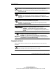
F Probability of Logical Drive Failure The probability that a logical drive will fail depends on the RAID level setting. • A RAID 0 logical drive fails if only one physical drive fails. • For a RAID 1+0 logical drive, the failure situation is complex. — The maximum number of physical drives that can fail without causing failure of the logical drive is n/2, where n is the number of hard drives in the array. This maximum is reached only if no failed drive is mirrored to any other failed drive.
Probability of Logical Drive Failure Increasing likelihood of logical drive failure > > > RAID 0 RAID 5 RAID 1+0 RAID ADG 1 6 11 16 21 26 31 36 41 46 51 56 Total number of physical drives in array Figure F-1: Relative probability of logical drive failure F-2 Compaq Smart Array 5300 Controller User Guide COMPAQ CONFIDENTIAL Writer: John Turner File Name: p-appf probability of logical drive failure.
G POST Error Messages Smart Array controllers produce diagnostic error messages at reboot. Many of these Power-On Self-Test (POST) messages are self-explanatory and suggest corrective actions for troubleshooting. Detailed information about these messages is given in Table G-1. Table G-1: POST Error Messages Message Description Meaning and Recommended Action 1702 SCSI cable error detected. System halted. There is a termination or cabling problem with the system board integrated SCSI controller.
POST Error Messages Table G-1: POST Error Messages continued Message Description Meaning and Recommended Action 1720 Slot x drive array – S.M.A.R.T. hard drive detects imminent failure: SCSI port x: SCSI ID y The indicated drive has reported a S.M.A.R.T. predictive-failure condition. It may fail at some time in the near future. Do not replace the drive unless all other drives on the array are online! Back up data before replacing drive(s).
POST Error Messages Table G-1: POST Error Messages continued Message Description Meaning and Recommended Action 1728 Slot x drive array – abnormal shutdown detected with write cache enabled. This message should never occur unless the write cache is somehow enabled on a controller that does not have batteries. No array accelerator battery backup on this model array controller. Any data that may have been in array accelerator memory has been lost.
POST Error Messages Table G-1: POST Error Messages continued Message Description Meaning and Recommended Action 1758 Slot x drive array – array accelerator size mismatch between controllers. 64MB array accelerator should be attached to both controllers. The size of the array accelerators is different between two controllers in a redundant controller configuration. Use array accelerators of the same size on both controllers.
POST Error Messages Table G-1: POST Error Messages continued Message Description Meaning and Recommended Action 1768 Slot x drive array – resuming logical drive expansion process. No action required. This message appears whenever a controller reset or power cycle occurs while array expansion is in progress. 1769 Slot x drive array – drive(s) disabled due to failure during expansion (possibly followed by additional details).
POST Error Messages Table G-1: POST Error Messages continued Message Description Meaning and Recommended Action 1776 Slot x drive array – SCSI bus termination error – internal and external drives cannot both be attached to the same SCSI port. The internal and external connectors of the specified SCSI port(s) are both attached to drives. The SCSI bus is not properly terminated when internal and external drives are attached concurrently to the same SCSI bus.
POST Error Messages Table G-1: POST Error Messages continued Message Description Meaning and Recommended Action 1779 Slot x drive array – replacement drive(s) detected or previously failed drive(s) now appear to be operational: If this message appears and drive x has not been replaced, an intermittent drive failure has occurred. This message also appears once immediately following drive replacement before data is restored from backup.
POST Error Messages Table G-1: POST Error Messages continued Message Description Meaning and Recommended Action 1785 Slot 1 Drive Array not Configured (may be followed by one of the following messages): (1) Turn off the system and check SCSI cable connections to be sure that drives are attached properly. (1) No drives detected (2) Run the Array Diagnostics Utility (ADU) if previous positions are unknown. Then power the system down and move drives to their original positions.
POST Error Messages Table G-1: POST Error Messages continued Message Description Meaning and Recommended Action 1786 Slot x Drive Array Recovery Needed. The following SCSI drive(s) need Automatic Data Recovery: SCSI port (y): SCSI ID (x) The message normally appears when a drive is replaced in a fault-tolerant configuration when the system is powered down. In this case, press the F1 key to start the automatic data recovery process. Select F1 to continue with recovery of data to drive(s).
POST Error Messages Table G-1: POST Error Messages continued Message Description Meaning and Recommended Action 1788 (1) Slot x drive array reports incorrect drive replacement. The following SCSI drive(s) should have been replaced: SCSI port (y): SCSI ID (x). (1) The drives indicated were installed in the wrong place, so they have been disabled. Reinstall the drives correctly. The following SCSI drive(s) were incorrectly replaced: SCSI port (y): SCSI ID (z).
POST Error Messages Table G-1: POST Error Messages continued Message Description Meaning and Recommended Action 1793 Slot x drive array – array accelerator battery depleted. Data in array accelerator has been lost. (Error message 1794 is also displayed.) While the system was in use, power was interrupted while data was in the array accelerator memory. Power was not restored within four days, so the batteries were depleted and data in the array accelerator was lost.
POST Error Messages Table G-1: POST Error Messages continued Message Description Meaning and Recommended Action 1798 Slot x drive array – array accelerator write error occurred. Array accelerator is disabled. Replace the array accelerator or the Smart Array controller. Restore data from backup. 1799 Slot x drive array – drive(s) disabled due to array accelerator data loss. Select F1 to continue with logical drives disabled. Select F2 to accept data loss and re-enable logical drives.
H Questions and Answers Q: How many Smart Array 5300 Controllers can I install in my system? A: The maximum number of controllers that you can install in your system depends on your server and several other factors specific to your configuration. Generally, the maximum number is restricted to the number of PCI slots not used for other peripherals. Another limiting factor is the power rating of your system. Each Smart Array 5300 Controller requires 21.2 W (or 24.9 W if it has four channels).
Questions and Answers Q: I installed the hard drives in my server. Must I now terminate each drive? A: No. If you installed hard drives in a server with a Smart Array controller, the I/O board and the hot-plug backplane in the server meet all termination requirements. Individual hot-pluggable drives should already have termination removed. Q: What is the data transfer rate for Wide Ultra3 SCSI? A: Wide Ultra3 SCSI has a data bandwidth of 160 MB per second.
Questions and Answers Q: I am planning to install several hard drives in my Compaq servers. Can I install each drive in any drive bay? A: Yes, you may install these drives in any drive bay; they do not need to be installed in contiguous bays. Q: I ordered my server with a pre-installed Smart Array controller. How do I order cables to connect to my Compaq external storage enclosure? A: The required cable is supplied with the external storage enclosure.
Questions and Answers Also, Compaq offers a unique Pre-Failure Warranty for all drives—valid only when using Compaq drives, Compaq array controllers, and Compaq Insight Manager. Contact your dealer for more information about the Compaq Pre-Failure Warranty. Q: Why do the drive activity LEDs light up on some drives when my system is idle? A: The Smart Array controller performs several different background activities on the drives when the controller is otherwise idle.
Glossary ACU (Array Configuration Utility) A configuration utility useful both for novices and for more experienced RAID users. Obtained either from the SmartStart CD or as a download from the Compaq website. ADU (Array Diagnostic Utility) A diagnostic tool that collects comprehensive information about the array controllers in a system and lists any problems detected. ARM (Auto-Reliability Monitoring) Also known as surface analysis.
Glossary Automatic Data Recovery Also known as rebuild. A process that automatically reconstructs data from a failed drive and writes it onto a replacement drive. Rebuild time depends on several factors, but at least 15 minutes should be allowed per gigabyte. cache A high-speed memory component, used to store data temporarily for rapid access. capacity expansion Abbreviation for array capacity expansion.
Glossary data guarding See RAID. data striping Writing data to logical drives in interleaved chunks (by byte or by sector). This technique improves system performance. drive mirroring See RAID. ECC (error correction and checking) memory A type of memory that checks and corrects single-bit or multi-bit memory errors (depending on configuration) without causing the server to halt or corrupt data.
Glossary online spare Also known as a hot spare, this is a drive in a fault-tolerant system that normally contains no data. When any other drive in the array fails, the controller automatically rebuilds the missing data that was on the failed drive onto the online spare. The controller constructs the missing data from the duplicate or parity data that is on the remaining drives in the array.
Glossary SE (single-ended) A type of SCSI signaling that allows a maximum transfer rate of 40 MB/s. Conforms to the Wide-Ultra SCSI standard. Now being phased out in favor of LVD technology. S.M.A.R.T. (Self-Monitoring, Analysis, and Reporting Technology) Technology co-developed by Compaq and the hard drive industry that provides warning of imminent drive failure. This feature makes it possible for Compaq to offer Pre-Failure Warranty replacement of hard drives. S.M.A.R.T.
Glossary VHDCI (Very High Density Cable Interconnect) A type of external SCSI connector used by Ultra SCSI controllers. Wide-Ultra; Wide Ultra2; Wide Ultra3 A set of SCSI standards that support maximum signal transfer rates of 40 MB/s, 80 MB/s, and 160 MB/s, respectively. Glossary-6 Compaq Smart Array 5300 Controller User Guide COMPAQ CONFIDENTIAL Writer: John Turner File Name: w-glossary.
Index A accelerator ratio setting in ACU 7-10 in CPQONLIN 7-32 ACU (Array Configuration Utility) adding spare drive with 7-18 array capacity expansion with 7-20 comparison of, with other configuration utilities 7-2 configuration wizard in 7-4 identifying drives using 7-8 limitations of 7-2 logical drive creation example 7-19 logical drive extension in 7-23 manual configuration with 7-16 NetWare and 7-5 RAID level migration with 7-25 running from CD 7-5 running while online 7-5 screen descriptions 7-5 sourc
Index array capacity expansion description of E-11 using ACU 7-20 using CPQONLIN 7-33 Array Configuration Utility See ACU array controller configuration of 7-1 dimensions of C-1 driver installation for 8-1 duplexing of D-11 installation of 2-1, 3-1 interface of, with server 1-8 performance of, optimizing, in NetWare 5-6 port use, restriction on 1-2, 3-6 power requirement of C-1, H-1 replacement of 3-2 Array Diagnostic Utility (ADU) E-4 array expansion, priority of, setting in ACU 7-10 in CPQONLIN 7-32 auto
Index capacity upgrade of hard drives E-10 CD-ROM drives, support for H-1 channel adapter board illustrated 1-3 Compaq authorized reseller xiii Compaq Insight Management Agents 8-2 Compaq Insight Manager drive failure detection with E-4 error counters in E-6 Compaq series number A-1 Compaq Support Paq diskettes 8-2 Compaq website xii comparison of ACU with ORCA 7-2 of different RAID methods D-10 of hardware-based RAID with softwarebased RAID D-11 of logical drive failure risk for different RAID levels F-2
Index data reliability features ECC memory 1-6 general 1-8 data stripes, defined D-2 data transfer rate C-1, H-2 Declaration of Conformity A-3 default stripe size 7-13 device driver installation 8-1 device priority, setting 3-3 diagnosing problems error messages in POST G-1 of hard drive E-4 dimensions of controller C-1 discharged batteries 1-7 diskettes CSP (Compaq Support Paq) 8-2 Options ROMPaq 5-3 SSD See CSP (Compaq Support Paq) System ROMPaq 4-2 distributed data guarding (RAID 5) D-7 documents xi dri
Index supported, list of 1-8 fault tolerance See also RAID methods alternative methods of D-11 changing level of, in ACU 7-25 changing level of, in CPQONLIN 7-34 compromised E-4 controller duplexing as D-11 description of methods D-4 software-based RAID as D-11 stripe size and 7-13 supported methods of 1-4 FCC notices A-1 features fault management 1-8 of ACU 7-2 of array accelerator 1-5 of controller C-1 of CPQONLIN 7-2 of ORCA 7-2 of RAID methods D-10 Federal Communications Commission notices See FCC noti
Index I installing adapter board 9-8 array accelerator 9-1 batteries 9-4 cache 9-1 controller hardware 3-1 controller, flowcharts for 2-1 CPQONLIN 7-26 device drivers 8-1 multiple array controllers H-1 interim data recovery description of 1-9 limitation of D-11 internal cabling 3-4 internal connectors on board 1-2 J jumpers, setting 3-4, H-2 L LEDs blinking 7-8, E-3 identifying drives by, in ACU 7-8 interpreting drive status by E-2 lit on idle system H-4 limitations on ACU use 7-2 controller port use 3-6
Index memory allocation of, to cache, in ACU 7-10 allocation of, to cache, in CPQONLIN 7-32 array accelerator 1-6 ECC SDRAM 1-6 linear 5-6 required amount of, for stripe size change 7-25 migration caution for 7-12 in ACU 7-25 in CPQONLIN 7-34 time required for 7-25, 7-34 minimum cache memory required for stripe size change 7-25 capacity of spare drive 7-18 number of hard drives for RAID D-10 mirroring of drives D-6 mouse compliance statement A-4 moving cache 1-6 drives E-9 multi-device cable 3-5 multiple c
Index overview of controller features 1-4 of installation process 2-1 P parity data in RAID 5 D-7 in RAID ADG D-9 part numbers for cables 3-5, 3-6 partition, creating in NetWare 5-6 using SCU 5-6 parts, handling and storing B-1 PCI-X interface characteristics 1-8 performance linear memory and 5-6 of controller, optimizing, in NetWare 5-6 of SCSI devices 1-8 of Wide Ultra3 SCSI devices H-2 performance tuning 7-13 peripherals, SCSI ID of 3-3 physical drives See hard drives port use, restriction on 1-2, 3-6
Index recovering data, general information for E-4 Recovery ROM 1-10 regulatory compliance notices A-1 replacing adapter board 9-8 array accelerator 9-1 batteries 9-4 cache 9-1 existing controller 3-2 hard drive E-7, E-8 Smart controller, restriction on 3-4 reprogramming options ROM 5-1 system ROM 4-1 resources ACU 7-1 ACU-XE 7-1 Array Diagnostic Utility E-4 automatic data recovery E-5 Compaq Insight Management Agents 8-2 Compaq Insight Manager 1-10 CPQONLIN 7-1, 7-26 Options ROMPaq 5-1 ORCA 6-3, 7-1 POST
Index SoftPaq file location of 4-1 Options ROMPaq diskettes from 5-4 System ROMPaq diskette from 4-2 spare drives adding to array, using ACU 7-18 adding to array, using CPQONLIN 7-31 adding to array, using ORCA 7-3 defined D-5 multiple, per array 7-18 required capacity of 7-18 sharing among arrays 7-18 support for 1-4 SSD (support software diskette) See CSP static-safe containers B-1 status LEDs, on drives E-2 storage capacity, expanding using ACU 7-20 using CPQONLIN 7-33 StorageWorks Enclosure 4300, conne
Index system firmware 4-1 system partition 5-6 upgrading array accelerator 9-1 cache 9-1 hard drive capacity E-10 utilities ACU 7-1 ACU-XE 7-1 Array Diagnostic Utility E-4 CPQONLIN 7-1, 7-26 NetWare array configuration utility 7-26 ORCA 6-3, 7-1 POST G-1 RBSU 6-1 System Configuration Utility 5-6 System ROMPaq 4-1 V VHDCI cable 3-5 VHDCI connector on board, illustration of 1-2 volume, creating, in NetWare 5-6 W website, Compaq xii Wide Ultra2 SCSI, support for 1-8 Wide Ultra3 SCSI cable, part number for