
HP StorageWorks Modular Smart Array Controller, Cache, and Battery Replacement Instructions (February 2006)


*383078-002*
383078–002
About this document
This document details procedures for replacing a controller, controller
cache module, or cache batteries in HP StorageWorks Modular Smart
Array (MSA) 1000, 1500 cs, and 1510i products.
Before you begin
CAUTION: Be sure the replacement is available before removing
the failed component. Removing a component impacts airflow and
cooling within the enclosure.
CAUTION: Follow these instructions when replacing components.
If the procedure is done improperly, it is possible to lose data or
damage equipment.
CAUTION: When handling system components, there is a
danger to equipment from electrostatic discharge (ESD). Use proper
anti-static protection at all times:
• Keep the replacement component in the ESD bag until needed.
• Wear an ESD wrist strap grounded to an unpainted surface of the
chassis.
• If an ESD wrist strap is unavailable, touch an unpainted surface of
the chassis before handling the component.
• Never touch connector pins.
See your user documentation for additional information.
Using this document
Your replacement procedures may not require all steps listed in this
document.
• Controller replacement—Use steps 1, 2, 4, and 5.
• Controller cache module replacement—Use steps 1, 2, 4, and 5.
• Controller cache battery replacement—Use steps 1, 2, 3, 4, and 5.
Verifying component failure
Before replacing a controller, cache module, or battery pack:
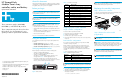
• Check the controller heartbeat LED (1).
If the LED is not blinking, it might indicate a failure.
• Check the controller fault LED (2).
If the LED is on, it might indicate a failure. Check for an error
message listed in Table 1 and take appropriate action.
• Remove the controller, wait 10 seconds, and then reinsert it,
ensuring that it is fully seated in the chassis. If this does not resolve
the issue, continue with the replacement procedures.
Figure 1 MSA controller
Stopping access to the controller
Single controller configurations
To service a failed or operational controller:
1. Ensure that a known, good backup is available.
2. Schedule a maintenance window.
3. From the servers, stop all access to the MSA.
4. Power off the MSA and disconnect the power cords to prevent any
new access.
Dual-controller configurations
If one of the two controllers has failed, you may remove the failed
controller for servicing at any time.
If both controllers are operational, but one or both of them need
servicing, you can schedule a maintenance window to perform the
service, or do the following to disable and service the standby
controller while operating in a non-redundant mode from the active
controller.
1. Access the management utility for your MSA:
IMPORTANT: During this procedure, because you disable the
controller being removed, you temporarily operate in a non-redundant
mode.
2. In your chosen management utility, disable the controller to be
removed. For details, see online help or your user documentation.
3. Wait for the following LCD message to be displayed before
removing the controller:
204 ARRAY CONTROLLER DISABLED
IMPORTANT: If an operational controller is removed from the
chassis without first being disabled, the active controller might halt. To
clear this fault condition, power cycle the MSA.
Replacing the controller/components
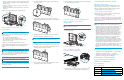
Step 1: Remove the controller
1. Press the controller thumb latch and rotate the latch handle out (1).
2. Pull the controller straight out of the chassis (2).
Step 2: Remove the cache module
(if applicable)
NOTE: If you are not replacing controller cache modules,
proceed to Step 3.
IMPORTANT: Replacement controllers include a new cache
module. Remove this new module from the replacement controller and
replace it with the cache module from the failed controller. Using the
same cache module completes disk writes trapped in the cache.
IMPORTANT: When replacing a controller cache module in a
dual-controller configuration, the memory size of the new module must
be identical to that of the already installed module.
NOTE: The controller in the following illustration has been rotated
to show the side and rear of the controller.
15192
1 2
Table 1 Controller error messages
Number Message text
03 CRITICAL LOCK-UP DETECTED. CODE=<n>h
43 REDUNDANCY FAILED HARDWARE FAILURE
66 CACHE HARDWARE FAILED AND DISABLED
204 ARRAY CONTROLLER DISABLED
305 ROM CLONING FAILED
308 FIRMWARE FLASH FAILED
317 ISCSI MODULE FLASH FAILED
501 PCI SUBSYSTEM HARDWARE FAILURE
502 PCI BRIDGE ASIC SELF TEST FAILURE
513 UNCORRECTED ECC MEMORY ERROR SEEN
515 FIBRE DEVICE HARDWARE FAILURE
524 ISCSI MODULE HARDWARE FAILURE
Table 2 Available management utilities
MSA model Available management utilities
MSA1000 Command Line Interface
MSA1500 cs Array Configuration Utility, Command Line Interface
MSA1510i Storage Management Utility, Command Line Interface
2
15181
1
HP StorageWorks
Modular Smart Array
controller, cache, and battery
replacement instructions
These instructions apply to MSA1000,
MSA1500 cs, and MSA1510i products.
These components may also be used in other
HP products. See documentation for your
specific product for replacement instructions.
© Copyright 2005-2006 Hewlett-Packard Development Company, L.P.
Second edition February 2006
Product names mentioned herein may be trademarks of their respective
companies as reflected by an associated footnote.
Information in this document is subject to change without notice.
Printed in the US.
www.hp.com