HP Smart Array E500 Controller User Guide Part Number 444373-001 January 2007 (First Edition)
© Copyright 2007 Hewlett-Packard Development Company, L.P. The information contained herein is subject to change without notice. The only warranties for HP products and services are set forth in the express warranty statements accompanying such products and services. Nothing herein should be construed as constituting an additional warranty. HP shall not be liable for technical or editorial errors or omissions contained herein.
Contents Hardware features ........................................................................................................................ 5 Main components on the board .................................................................................................................. 5 Other features........................................................................................................................................... 5 Overview of the installation procedure ...................
Diagnostic tools ...................................................................................................................................... 30 Electrostatic discharge ................................................................................................................. 32 Preventing electrostatic discharge .............................................................................................................. 32 Grounding methods to prevent electrostatic discharge .............
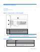
Hardware features In this section Main components on the board ................................................................................................................. 5 Other features..........................................................................................................................................
Maximum power required Approximately 14 W Temperature range Operating, 10° to 55°C (50° to 131°F) Storage, -30° to 60°C (-22° to 140°F) Relative humidity (noncondensing) Operating, 10% to 90% Storage, 5% to 90% RAID levels supported 0, 1, and 1+0; also RAID 5 if the battery kit option is used Battery kit option part numbers Battery pack 383280-B21; battery cable 417836-B21 Time required to recharge battery From 15 minutes to 2 hours, depending on the initial battery charge level Duration of batt
Overview of the installation procedure In this section Installing the controller in an unconfigured server ......................................................................................... 7 Installing the controller in a previously-configured server ............................................................................... 7 Installing the controller in an unconfigured server New HP ProLiant server models autoconfigure when they are powered up for the first time.
5. Power down peripheral devices. 6. Unplug the AC power cord from the server. 7. Disconnect peripheral devices. 8. Install the controller hardware ("Installing the controller hardware" on page 9). 9. Connect storage devices to the controller ("Connecting external storage" on page 10). 10. Reconnect peripheral devices and the AC power supply to the server. 11. Power up peripheral devices. 12. Power up the server. 13.
Installing the controller hardware In this section Preparing the server ................................................................................................................................. 9 Installing the controller board .................................................................................................................... 9 Connecting external storage ....................................................................................................................
6. Connect storage devices to the controller. (For details of the procedure, see "Connecting storage devices ("Connecting external storage" on page 10).") 7. Close or replace the access panel, and secure it with thumbscrews, if any are present. CAUTION: Do not operate the server for long periods with the access panel open or removed. Operating the server in this manner results in improper airflow and improper cooling that can lead to thermal damage. Connecting external storage 1. Power down the server.
Updating the firmware In this section Methods for updating the firmware........................................................................................................... 11 Methods for updating the firmware To update the firmware on the server, controller, or hard drives, use Smart Components. These components are available on the Firmware Maintenance CD. A more recent version of a particular server or controller component might be available on the support page of the HP website (http://www.hp.
Configuring an array In this section Utilities available for configuring an array................................................................................................. 12 Utilities available for configuring an array Three utilities are available for configuring an array on an HP Smart Array controller: ORCA, CPQONLIN, and ACU. • ORCA is a simple utility that is used mainly to configure the first logical drive in a new server before the operating system is loaded.
Setting the boot controller and controller order In this section Setting a controller as the boot controller .................................................................................................. 13 Setting the controller order ...................................................................................................................... 13 Setting a controller as the boot controller The following procedure enables you only to set a controller as the boot controller.
5. Exit from the utility. For more information about using RBSU, refer to the HP ROM-Based Setup Utility User Guide or the server setup and installation guide. These documents are both available on the Documentation CD supplied in the server kit.
Installing device drivers and Management Agents In this section Installing device drivers........................................................................................................................... 15 Installing Management Agents .................................................................................................................
Upgrading or replacing controller options In this section Installing or replacing a battery ............................................................................................................... 16 Replacing the cache ...............................................................................................................................
4. Plug the other end of the battery cable into the connector on the cache module. After installing a battery pack, you might see a POST message during reboot indicating that the array accelerator (cache) is temporarily disabled. This behavior is normal because the new battery pack is likely to have a low charge. You do not need to take any action because the recharge process begins automatically when the battery pack is installed.
4. Unplug the cable from the battery pack. 5. Remove the battery pack from the server. 6. Plug the cable into the new battery pack. 7. Install the new battery pack into the server. 8. Verify that the other end of the cable is properly seated in the cache connector. NOTE: After installing a battery pack, you might see a POST message during reboot indicating that the array accelerator (cache) is temporarily disabled. This is normal, because the new battery pack is likely to have a low charge.
o If the LED is not lit, disconnect the battery cable from the cache. 4. Remove the controller from the server and place it on a firm, flat, nonconductive surface. 5. Remove the existing cache from the controller by pulling at both ends of the cache module with equal force. 6. Install the new cache on the controller. Press firmly above each connector to ensure good electrical contact. (If the cache is not properly connected, the controller cannot boot.) 7. Replace the controller in the server. 8.
Replacing, moving, or adding hard drives In this section Identifying the status of a hard drive ......................................................................................................... 20 Recognizing hard drive failure................................................................................................................. 21 Replacing hard drives .............................................................................................................................
Online/activity LED (green) Fault/UID LED (amber/blue) Interpretation Flashing regularly (1 Hz) Amber, flashing regularly (1 Hz) Do not remove the drive. Removing a drive may terminate the current operation and cause data loss. The drive is part of an array that is undergoing capacity expansion or stripe migration, but a predictive failure alert has been received for this drive. To minimize the risk of data loss, do not replace the drive until the expansion or migration is complete.
Effects of a hard drive failure When a hard drive fails, all logical drives that are in the same array are affected. Each logical drive in an array can use a different fault-tolerance method, so each logical drive can be affected differently. • RAID 0 configurations cannot tolerate drive failure. If any physical drive in the array fails, all nonfault-tolerant (RAID 0) logical drives in the same array will also fail.
Replacing hard drives The most common reason for replacing a hard drive is that it has failed. However, another reason is to gradually increase the storage capacity of the entire system. If you insert a hot-pluggable drive into a drive bay while the system power is on, all disk activity in the array pauses for a second or two while the new drive is spinning up.
Automatic data recovery (rebuild) When you replace a hard drive in an array, the controller uses the fault-tolerance information on the remaining drives in the array to reconstruct the missing data (the data that was originally on the replaced drive) and write it to the replacement drive. This process is called automatic data recovery, or rebuild. If fault tolerance is compromised, this data cannot be reconstructed and is likely to be permanently lost. Fault tolerance is unavailable during a rebuild.
Observation Cause of rebuild termination None of the drives in the array have an illuminated amber Fault LED. One of the drives in the array has experienced an uncorrectable read error. The replacement drive has an illuminated amber Fault LED. The replacement drive has failed. One of the other drives in the array has an illuminated amber Fault LED. The drive with the illuminated Fault LED has now failed. Each of these situations requires a different remedial action.
Upgrading hard drive capacity You can increase the storage capacity on a system even if there are no available drive bays by swapping drives one at a time for higher capacity drives. This method is viable as long as a fault-tolerance method is running. CAUTION: Because it can take up to 30 seconds per gigabyte to rebuild the data in the new configuration, the system could be unprotected against drive failure for many hours while the drives are upgraded.
4. Power up the system. If a 1724 POST message appears, drive positions were changed successfully and the configuration was updated. If a 1785 (Not Configured) POST message appears: a. Power down the system immediately to prevent data loss. b. Return the drives to their original locations. c. 5. Restore the data from backup, if necessary. Verify the new drive configuration by running ORCA or ACU ("Configuring an array" on page 12).
Diagnosing array problems In this section Controller board runtime LEDs.................................................................................................................. 28 Battery pack LEDs................................................................................................................................... 29 Diagnostic tools .....................................................................................................................................
LED ID Color LED name and interpretation 8 Green CR7: Idle Task LED. This LED, together with LED 7, indicates the amount of controller CPU activity. For details, see the following table. Controller CPU activity level LED 7 status LED 8 status 0–25% Off Flashing 25–50% Flashing Off 50–75% On steadily Off 75–100% On steadily On steadily Battery pack LEDs Item ID Color Description 1 Green System Power LED.
LED3 pattern LED4 pattern Interpretation — One blink every two seconds The system is powered down, and the cache contains data that has not yet been written to the drives. Restore system power as soon as possible to prevent data loss. Data preservation time is extended any time that 3.3 V auxiliary power is available, as indicated by LED 2. In the absence of auxiliary power, battery power alone preserves the data. A fullycharged battery can normally preserve data for at least two days.
Smart Array controllers produce diagnostic error messages (POST messages) at reboot. Many POST messages are self-explanatory and suggest corrective actions. For more information about POST messages, see the HP Servers Troubleshooting Guide. • HP Insight Diagnostics HP Insight Diagnostics is a tool that displays information about the system hardware configuration and performs tests on the system and its components (including hard drives if they are connected to Smart Array controllers).
Electrostatic discharge In this section Preventing electrostatic discharge............................................................................................................. 32 Grounding methods to prevent electrostatic discharge ................................................................................ 32 Preventing electrostatic discharge To prevent damaging the system, be aware of the precautions you need to follow when setting up the system or handling parts.
Regulatory compliance notices In this section Federal Communications Commission notice ............................................................................................. 33 Modifications......................................................................................................................................... 33 Cables ..................................................................................................................................................
European Union regulatory notice This product complies with the following EU Directives: • Low Voltage Directive 73/23/EEC • EMC Directive 89/336/EEC Compliance with these directives implies conformity to applicable harmonized European standards (European Norms) which are listed on the EU Declaration of Conformity issued by Hewlett-Packard for this product or product family.
Korean class A notice Battery replacement notice This component uses a nickel metal hydride (NiMH) battery pack. WARNING: There is a risk of explosion, fire, or personal injury if a battery pack is mishandled. To reduce this risk: • Do not attempt to recharge the batteries if they are disconnected from the controller. • Do not expose the battery pack to water, or to temperatures higher than 60°C (140°F). • Do not abuse, disassemble, crush, or puncture the battery pack. • Do not short the external contacts.
Acronyms and abbreviations ACU Array Configuration Utility ADU Array Diagnostics Utility BBWC battery-backed write cache CPQONLIN NetWare Online Array Configuration Utility OBDR One Button Disaster Recovery ORCA Option ROM Configuration for Arrays POST Power-On Self Test RBSU ROM-Based Setup Utility SA Smart Array Acronyms and abbreviations 36
Index A E ACU (Array Configuration Utility) 12 adding drives 27 ADU (Array Diagnostic Utility) 30 array controller installation overview 7 array expansion 27 array, configuring 12 array, moving 26 automatic data recovery (rebuild) 24 electrostatic discharge 32 environmental requirements 5 error messages 21, 30 European Union notice 34 Event Notification service 30 expanding an array 27 extending logical drive capacity 27 B batteries, replacing 16, 17 battery pack LEDs 29 battery replacement notice 35 ba
K T Korean notices 35 Taiwan battery recycling notice 35 temperature requirements 5 troubleshooting 30 L LEDs, battery pack 29 LEDs, controller 28 LEDs, hard drive 20 logical drive capacity extension 27 logical drive, creating 12 U unconfigured server, installation in 7 updating the firmware 11 upgrading drive capacity 26 M Management Agents, updating 15 modifications, FCC notice 33 moving an array 26 O ORCA (Option ROM Configuration for Arrays) 12, 13 overview of installation process 7 P POST error