HP Smart Array Controllers for HP Integrity Servers User Guide Part Number 469987-002 March 2009 (Second Edition)
© Copyright 2008, 2009 Hewlett-Packard Development Company, L.P. The information contained herein is subject to change without notice. The only warranties for HP products and services are set forth in the express warranty statements accompanying such products and services. Nothing herein should be construed as constituting an additional warranty. HP shall not be liable for technical or editorial errors or omissions contained herein. Microsoft, Windows, and Windows Server are U.S.
Contents Hardware features ........................................................................................................................ 5 E500 model ............................................................................................................................................. 5 P700m model ........................................................................................................................................... 6 P800 model .........................................
Replacing hard drives .............................................................................................................................. 35 Factors to consider before replacing hard drives................................................................................ 35 Automatic data recovery (rebuild) .................................................................................................... 36 Upgrading hard drive capacity ............................................................
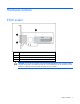
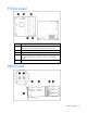
Hardware features E500 model Item ID Description 1 Connector for mini-SAS port 1E (external), 4x wide 2 Connector for mini-SAS port 2E (external), 4x wide 3 40-bit, 256-MB cache module (also known as array accelerator) CAUTION: Do not use this controller with cache modules designed for other controller models, because the controller can malfunction and you can lose data. Also, do not transfer this cache module to a different controller module, because you can lose data.
P700m model Item ID Description 1 Status LEDs (runtime LEDs). To interpret the illumination pattern of these LEDs, see "Controller board runtime LEDs (on page 41)". 2 Connector (not used on HP Integrity servers). 3 Cache module (also known as array accelerator). 4 Connector for the cable to an optional cache battery that upgrades the cache to BBWC. This connector is absent on some P700m models. 5 Mezzanine connector to system board.
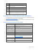
Item ID Description 1 Connector for mini-SAS ports 1E and 2E (external), each 4x wide 2 Heartbeat LED (flashes green when operating normally and amber if the board has failed) 3 Activity LED for external ports 4 SAS port 3I (internal), 4x wide 5 SAS port 4I (internal), 4x wide 6 Cache module (also known as array accelerator) 7 (Optional) Batteries for cache module Two batteries are normally sufficient, but you can add a third battery to provide extra security against loss of system power.
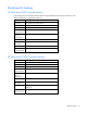
Model-specific features HP Smart Array E500 Controller features In HP Integrity servers, the E500 controller does not support RAID-level or stripe-size migration, array capacity expansion, or logical drive extension. Feature Description Board type Low-profile, PCIe stand-up board Dimensions, cm* 16.8 x 7.0 x 1.8 Dimensions, in* 6.6 x 2.8 x 0.
HP Smart Array P800 Controller features Feature Description Board type Full-size, PCIe stand-up board Dimensions, cm* 31.1 x 11.1 x 1.2 Dimensions, in* 12.3 x 4.4 x 0.
Overview of the installation procedure Quick installation procedure (Windows or Linux) Before installing the controller, refer to the support matrix on the HP website (http://www.hp.com/products1/serverconnectivity) to confirm that the server and operating system support the controller. To install the controller: 1. Power down the server. 2. Unplug the AC power cord from the power outlet. 3. Unplug the power cord from the server. 4.
The latest firmware, drivers, utilities, software, and documentation for HP Integrity servers are available on the support page of the HP website (http://www.hp.com/support/itaniumservers).
Installing the controller hardware Preparing the server 1. Back up all data. 2. Close all applications. 3. Power down the server. CAUTION: In systems that use external data storage, be sure that the server is the first unit to be powered down and the last to be powered back up. Taking this precaution ensures that the system does not erroneously mark the drives as failed when the server is powered up. 4. Power down all peripheral devices that are attached to the server. 5.
8. Close or replace the access panel, and then secure it with thumbscrews, if any are present. CAUTION: Do not operate the server for long periods with the access panel open or removed. Operating the server in this manner results in improper airflow and improper cooling that can lead to thermal damage. Connecting storage devices Depending on the controller model, you can connect SAS or SATA drives to the controller internally ("Connecting internal storage" on page 13), externally, or both.
3. Connect the other end of the cable to the SAS input connector of the external storage enclosure: o If the enclosure uses a standard SAS 4x connector, insert the cable connector into the enclosure connector, and then tighten the lock screws on the cable connector. o If the enclosure uses a mini SAS 4x connector, pull back the tab on the cable connector, insert the cable connector into the enclosure connector, and then release the tab. 4. Power up the enclosure. 5. Power up the server.
Updating the firmware Methods for updating the firmware (Windows or Linux) To update the firmware on the server, controller, or hard drives, use Smart Components. The most recent version of a particular component is available on the support page of the HP website (http://www.hp.com/support). Some components are also available on the Smart Setup media. 1. Find the most recent version of the component that you require. 2. Follow the instructions for installing the component on the server.
Configuring an array Utilities available for configuring an array Two utilities are available for configuring an array on an HP Smart Array controller in an HP Integrity server: ORCA and ACU. • ORCA is a simple utility that is used mainly to configure the first logical drive in a new server before the operating system is loaded. • ACU is an advanced utility that enables you to perform many complex configuration tasks.
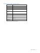
Supported procedures ACU ORCA Assignment of RAID level + + Sharing of spare drives among several arrays + -- Assignment of multiple spare drives per array + -- Setting of stripe size + -- Migration of RAID level or stripe size + -- Configuration of controller settings + -- Expansion of an array + -- Creation of multiple logical drives per array + -- Using ORCA 1. Power up the server. POST runs, and any array controllers that are in the server are initialized one at a time.
The screen displays a list of all available (unconfigured) physical drives and the valid RAID options for the system. 2. Use the Arrow keys, Spacebar, and Tab key to navigate the screen and set up the logical drive, including an online spare drive if one is required. NOTE: You cannot use ORCA to configure one spare drive to be shared among several arrays. Only ACU enables you to configure shared spare drives. 3. Press the Enter key to accept the settings. 4.
Installing device drivers and Management Agents Systems using Microsoft Windows You can use the Integrity Support Pack to automatically install the device drivers, Event Notification Service, and Management Agents, or you can install these items manually. The Integrity Support Pack is located on the Smart Setup media. To install the Integrity Support Pack, launch Express Setup from EBSU and follow the on-screen instructions.
3. Follow the standard procedure for installing Linux. As Linux is installed, it recognizes the controller and automatically loads the correct driver. In a system that already has Linux installed: 1. Power down the system. 2. Follow the standard controller installation procedure. 3. Power up the system. As Linux boots, it recognizes the controller. 4.
Upgrading or replacing controller options Replacing the E500 cache CAUTION: Do not use this controller with cache modules designed for other controller models, because the controller can malfunction and you can lose data. Also, do not transfer this cache module to a different controller module, because you can lose data. 1. Close all applications, and then power down the server. This procedure flushes all data from the cache. 2. Disconnect the server from the AC power source. 3.
If the battery case is mounted on the inner wall of the server chassis: 1. Back up all data. 2. Close all applications. 3. Power down the server. 4. Remove the server from the enclosure. 5. Remove the server access panel. 6. Remove the battery case from the chassis wall. 7. Disconnect the cable from the battery. 8. Remove the battery from the battery case. 9. Install the replacement battery in the battery case. 10. Connect the battery cable to the replacement battery. 11.
9. Pull the right hand portion of the battery case away from the battery pack and simultaneously rotate the battery out of the opening. 10. Position the replacement battery pack in the opening in the battery case as shown. The upper left edge of the battery is under the flanges on the pillars at the left edge of the opening, and the right side of the battery rests on the right pillars.
11. Pull the right hand portion of the battery case away from the battery, and simultaneously rotate the battery pack into the opening. 12. Connect the battery cable to the battery and the cache. Route the battery cable so that the cache and battery can be removed together. (If you need to remove the cache to transfer data, the battery must remain connected to it so that the data is preserved.) 13. Insert the battery case into the hard drive slot. 14. Close the server access panel. 15.
3. Remove the controller from the server. 4. Pull the flanges on the battery clip outward (1), and then swivel the clip 180 degrees so that it rests on the batteries (2). 5. Slide the batteries toward the right edge of the controller, away from the bracket. 6. While holding the battery assembly, tilt the clip until it is at about 30 degrees to the batteries, and then push the clip in line with the clip hinges until the clip detaches from the batteries.
c. Slide the batteries apart (2). 8. Dispose of the exhausted or faulty battery using environmentally approved procedures ("Battery replacement notice" on page 51). 9. Position the new battery and the remaining good battery as indicated, push them together, and then slide them until they are aligned. The batteries combine into one unit. 10. Install the battery clip. a. Position the clip so that the hinges on the clip are next to the appropriate hinge pillars on the batteries. b.
c. 11. Push the clip at the hinges until the clip clicks into place. Reinstall the batteries. a. Hold the controller board near the DIMM socket and at the top and right edges to minimize bending of the board. b. Position the batteries so that the pegs A on the underside of each battery are in the appropriate holes B on the controller board and pegs C are in slots D.
c. 12. Slide the batteries toward the board bracket until they are firmly seated against the connectors on the cache module. Secure the battery clip to the controller board: a. Swivel the clip over the cache module (1). b. Push the clip firmly at both ends (2) until it clicks into place under the controller board. 13. Reinstall the controller in the server. After installing a battery pack, you might see a POST message during reboot indicating that the array accelerator (cache) is temporarily disabled.
Replacing the P800 cache module or controller CAUTION: Electrostatic discharge can damage electronic components. Be sure you are properly grounded before beginning this procedure. 1. Close all applications, and then power down the server. This procedure flushes all data from the cache. 2. Observe the BBWC Status LED ("Battery pack LEDs" on page 44). o If the LED is blinking every 2 seconds, data is trapped in the cache. Restore system power, and repeat the previous steps in this procedure.
6. Slide the battery assembly and the cache module off the controller board (2). The procedure at this point depends on whether you are replacing the controller or the cache module. 7. o If you are replacing the controller, go directly to the next step. o If you are replacing the cache module, pull it out of the battery assembly, install the new cache module in its place, and then go to the next step. Install the cache module and batteries on the controller board. a.
c. 8. Slide the batteries toward the board bracket until the connectors on the cache module are firmly seated in the DIMM connector. (When the cache module is correctly seated, the gold contacts on the cache module are completely hidden within the DIMM connector.) Secure the battery clip to the controller board. a. Swivel the clip over the cache module (1). b. Push the clip firmly at both ends (2) until it clicks into place under the controller board. 9. Reinstall the controller in the server.
Replacing, moving, or adding hard drives Identifying the status of a hard drive When a drive is configured as a part of an array and connected to a powered-up controller, the condition of the drive can be determined from the illumination pattern of the hard drive status lights (LEDs).
Online/activity LED (green) Fault/UID LED (amber/blue) Interpretation Flashing regularly (1 Hz) Amber, flashing regularly (1 Hz) Do not remove the drive. Removing a drive may terminate the current operation and cause data loss. The drive is part of an array that is undergoing capacity expansion or stripe migration, but a predictive failure alert has been received for this drive. To minimize the risk of data loss, do not replace the drive until the expansion or migration is complete.
CAUTION: Sometimes, a drive that has previously been failed by the controller may seem to be operational after the system is power-cycled or (for a hot-pluggable drive) after the drive has been removed and reinserted. However, continued use of such marginal drives may eventually result in data loss. Replace the marginal drive as soon as possible. Effects of a hard drive failure When a hard drive fails, all logical drives that are in the same array are affected.
b. Recreate the partitions. c. Restore all data from backup. To minimize the risk of data loss that is caused by compromised fault tolerance, make frequent backups of all logical volumes. Replacing hard drives The most common reason for replacing a hard drive is that it has failed. However, another reason is to gradually increase the storage capacity of the entire system.
• Do not remove a second drive from an array until the first failed or missing drive has been replaced and the rebuild process is complete. (The rebuild is complete when the Online/Activity LED on the front of the drive stops blinking.) The following cases are exceptions: o In RAID 6 (ADG) configurations, any two drives in the array can be replaced simultaneously.
CAUTION: If the Online/Activity LED on the replacement drive does not light up while the corresponding LEDs on other drives in the array are active, the rebuild process has abnormally terminated. The amber Fault LED of one or more drives might also be illuminated. Refer to "Abnormal termination of a rebuild (on page 37)" to determine what action you must take.
2. Remove the drive that was originally to be replaced, and reinsert the replacement physical drive. The rebuild process automatically restarts. 3. When the rebuild process has finished, replace the newly failed drive. However, if the newly failed drive has not recovered: 1. Remove the drive that was originally to be replaced, and reinsert the replacement physical drive. 2. Replace the newly failed drive. 3. Restore data from backup.
• The controller is not running capacity expansion, capacity extension, or RAID or stripe size migration. • The controller is using the latest firmware version (recommended). Before you move an array to another controller: • If the other controller is already connected to one or more arrays of configured logical drives, the total number of logical drives on the controller after the drives have been moved must not exceed the number of logical drives that the controller supports.
drive in the array. Each logical drive keeps the same fault-tolerance method in the enlarged array that it had in the smaller array. When the expansion process has finished, you can use the liberated storage capacity on the enlarged array to create new logical drives. Alternatively, you can use ACU to enlarge (extend) one of the original logical drives.
Diagnosing array problems Controller board runtime LEDs Immediately after you power up the server, the controller runtime LEDs illuminate briefly in a predetermined pattern as part of the POST sequence. At all other times during server operation, the illumination pattern of the runtime LEDs indicates the status of the controller. To determine the controller status, see the appropriate controller-specific section.
LED ID Color Name Comments 8 Green CR7: Idle Task This LED, together with the Gas Pedal LED (previous item), indicates the amount of controller CPU activity. For details, see the following table. Gas Pedal LED status Idle Task LED status Controller CPU activity level Off Blinking 0–25% Blinking Off 25–50% On steadily Off 50–75% On steadily On steadily 75–100% Runtime LEDs for P700m model LED ID Color Name Comments 1 Amber CR10: Thermal Alert This LED is not used.
LED ID Color Name Comments 9 Green CR7: Gas Pedal This LED, together with the Idle Task LED (next item), indicates the amount of controller CPU activity. For details, see the following table. 10 Green CR8: Idle Task This LED, together with the Gas Pedal LED (previous item), indicates the amount of controller CPU activity. For details, see the following table.
LED ID Color Name Comments 6 Green CR507: Activity Port 3I is active. 7 Green CR506: Command Outstanding The controller is working on a command from the host driver. 8 Green CR505: Controller Heartbeat When the controller is in good health, this LED flashes every two seconds. 9 Green CR504: Gas Pedal This LED, together with the Idle Task LED (next item), indicates the amount of controller CPU activity. For details, see the following table.
Item ID Color Description 2 Green Auxiliary Power LED. This LED glows steadily when 3.3V auxiliary voltage is detected. The auxiliary voltage is used to preserve BBWC data and is available any time that the system power cords are connected to a power supply. 3 Amber Battery Health LED. To interpret the illumination patterns of this LED, see the following table. 4 Green BBWC Status LED. To interpret the illumination patterns of this LED, see the following table.
• ADU This utility is a Windows®-based diagnostic tool that sends an email to HP Support when it detects any problems with the controllers and attached storage in a system. You can install ADU from the Smart Setup media. When installation is complete, run ADU by clicking Start, and then selecting Programs>HP System Tools>HP Array Diagnostic Utility. For the meanings of the various ADU error messages, see the troubleshooting chapter in the serverspecific service guide.
Electrostatic discharge Preventing electrostatic discharge To prevent damaging the system, be aware of the precautions you need to follow when setting up the system or handling parts. A discharge of static electricity from a finger or other conductor may damage system boards or other static-sensitive devices. This type of damage may reduce the life expectancy of the device. To prevent electrostatic damage: • Avoid hand contact by transporting and storing products in static-safe containers.
Regulatory compliance notices Federal Communications Commission notice Part 15 of the Federal Communications Commission (FCC) Rules and Regulations has established Radio Frequency (RF) emission limits to provide an interference-free radio frequency spectrum. Many electronic devices, including computers, generate RF energy incidental to their intended function and are, therefore, covered by these rules.
• Connect the equipment into an outlet on a circuit that is different from that to which the receiver is connected. • Consult the dealer or an experienced radio or television technician for help. Declaration of conformity for products marked with the FCC logo, United States only This device complies with Part 15 of the FCC Rules.
This Class B digital apparatus meets all requirements of the Canadian Interference-Causing Equipment Regulations. Cet appareil numérique de la classe B respecte toutes les exigences du Règlement sur le matériel brouilleur du Canada.
Japanese notice Korean notice Class A equipment Class B equipment Battery replacement notice This component uses a nickel metal hydride (NiMH) battery pack. WARNING: There is a risk of explosion, fire, or personal injury if a battery pack is mishandled. To reduce this risk: • Do not attempt to recharge the batteries if they are disconnected from the controller. • Do not expose the battery pack to water, or to temperatures higher than 60°C (140°F).
Batteries, battery packs, and accumulators should not be disposed of together with the general household waste. To forward them to recycling or proper disposal, use the public collection system or return them to HP, an authorized HP Partner, or their agents. For more information about battery replacement or proper disposal, contact an authorized reseller or an authorized service provider.
Acronyms and abbreviations ACU Array Configuration Utility ADG Advanced Data Guarding (also known as RAID 6) ADU Array Diagnostics Utility BBWC battery-backed write cache EBSU EFI-based setup utility EFI extensible firmware interface OBDR One Button Disaster Recovery ORCA Option ROM Configuration for Arrays POST Power-On Self Test Acronyms and abbreviations 53
Index A ACU (Array Configuration Utility) 16, 18 adding drives 39 ADU (Array Diagnostic Utility) 45 Array Configuration Utility (ACU) 16, 18 array controller installation overview 10 Array Diagnostic Utility (ADU) 45 array expansion 39 array, configuring 16 automatic data recovery (rebuild) 36 B batteries, replacing 21, 24 batteries, specifications 7 battery pack LEDs 44 battery replacement notice 51 board components, E500 5 board components, P800 6 BSMI notice 50 C cable part numbers 14 cables 49 cache,
J S Japanese notice 51 spares, battery pack, part number 8 spares, cable part numbers 14 specifications, controller 7 static electricity 47 status lights, battery pack 44 status lights, controller 41 status lights, hard drive 32 storage capacity, increasing 38 storage devices, connecting 13 summary of installation procedure 10 K Korean notices 51 L LEDs, battery pack 44 LEDs, controller 41 LEDs, E500 41 LEDs, hard drive 32 LEDs, P800 43 logical drive capacity extension 39 logical drive, creating 16 log