
HP Smart Array Controllers for HP Integrity Servers User Guide

Diagnosing array problems 41
Diagnosing array problems
Controller board runtime LEDs
Immediately after you power up the server, the controller runtime LEDs illuminate briefly in a
predetermined pattern as part of the POST sequence. At all other times during server operation, the
illumination pattern of the runtime LEDs indicates the status of the controller. To determine the controller
status, see the appropriate controller-specific section.
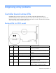
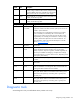
Runtime LEDs for E500 model
LED ID Color Name Comments
1 Amber CR14: Controller Lockup The controller ASIC has locked up and cannot
process any commands.
2 Amber CR13: Drive Failure To determine which drive has failed, check the
Fault LED of each physical drive connected to the
controller.
3 Green CR3: Activity Port 2E is active.
4 Green CR8: Activity Port 1E is active.
5 Green CR5: Command Outstanding The controller is working on a command from the
host driver.
6 Green CR6: Heartbeat When the controller is in good health, this LED
flashes every two seconds.
7 Green CR4: Gas Pedal This LED, together with the Idle Task LED (next
item), indicates the amount of controller CPU
activity. For details, see the following table.