HP Smart Array P400 Controller User Guide October 2005 (First Edition) Part Number 399716-001
© Copyright 2005 Hewlett-Packard Development Company, L.P. The information contained herein is subject to change without notice. The only warranties for HP products and services are set forth in the express warranty statements accompanying such products and services. Nothing herein should be construed as constituting an additional warranty. HP shall not be liable for technical or editorial errors or omissions contained herein.
Contents Hardware features ........................................................................................................................ 5 Board components .................................................................................................................................... 5 SAS/SATA connectors on the front of the board .................................................................................. 5 SAS/SATA connectors on the back of the board...................................
Upgrading hard drive capacity ....................................................................................................... 29 Moving drives and arrays ........................................................................................................................ 30 Adding drives ......................................................................................................................................... 30 Diagnosing array problems.............................................
Hardware features In this section Board components ................................................................................................................................... 5 Controller specifications ............................................................................................................................ 6 Board components Two models of the HP Smart Array P400 Controller are available.
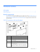
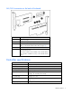
SAS/SATA connectors on the back of the board Item ID Description 1 Connectors for the cache module (also known as BBWC or array accelerator). 2 SAS or SATA port 1I (internal), 4x wide SFF8484 connector. 3 Runtime LEDs. To interpret the illumination pattern of these LEDs, see "Controller board runtime LEDs (on page 32)". 4 SAS or SATA port 2I (internal), 4x wide SFF8484 connector. 5 Cache module, showing the connector for the cable to the optional battery pack.
Time required to recharge battery From 15 minutes to two hours, depending on the initial battery charge level Duration of battery backup More than two days if the battery is fully-charged and less than three years old Battery life expectancy More than three years Type of edge connector PCIe x8 (fits in slots that have a physical size of x8 or greater; operates at the speed rating of the slot, up to a maximum of x8) PCI Express support 2.5 Gb/s PCI Express PCI Express transfer rate 2.
Overview of the installation procedure In this section Installing the controller in an unconfigured server ......................................................................................... 8 Installing the controller in a previously configured server ............................................................................... 8 Installing the controller in an unconfigured server New HP ProLiant server models self-configure when they are powered up for the first time.
. Update the Management Agents ("Installing Management Agents" on page 19) if new versions are available. The server is now ready to use. If you want to create additional logical drives, you may now do so.
Installing the controller hardware In this section Before beginning the installation .............................................................................................................. 10 Preparing the server ............................................................................................................................... 10 Installing the controller board ..................................................................................................................
4. Slide the controller board along the slot alignment guide if applicable, and press the board firmly into the slot so that the contacts on the board edge are properly seated in the system board connector. 5. Secure the controller board in place with the retaining screw. If there is a guide latch on the rear of the board, close the latch. 6. Connect storage devices to the controller. (For details of the procedure, see "Connecting storage devices (on page 11).
Updating the firmware In this section Methods for updating the firmware........................................................................................................... 12 Methods for updating the firmware To update the firmware on the server, controller, or hard drives, use Smart Components. These components are available on the Firmware Maintenance CD. A more recent version of a particular server or controller component might be available on the support page of the HP website (http://www.hp.
Configuring an array In this section Introduction ........................................................................................................................................... 13 Comparing the utilities ............................................................................................................................ 13 Using ORCA.......................................................................................................................................... 14 Using ACU .....
Supported features ACU CPQONLIN ORCA Uses a wizard to suggest the optimum configuration for an unconfigured controller + + -- Describes configuration errors + -- -- Supported procedures ACU CPQONLIN ORCA Creation and deletion of arrays and logical drives + + + Assignment of RAID level + + + Sharing of spare drives among several arrays + + -- Assignment of multiple spare drives per array + + -- Setting of stripe size + + -- Migration of RAID level or stripe size + + --
NOTE: You cannot use ORCA to configure one spare drive to be shared among several arrays. Only ACU enables you to configure shared spare drives. 3. Press the Enter key to accept the settings. 4. Press the F8 key to confirm the settings and save the new configuration. After several seconds, the Configuration Saved screen appears. 5. Press the Enter key to continue. You can now create another logical drive by repeating the previous steps.
3. Select the Controller Settings option below Controller Options. The Controller Settings screen appears. Drive rebuild Drive rebuild occurs after a physical drive fails and is replaced. Only logical drives that are configured with RAID 1+0, RAID 5, or RAID 6 (ADG) can be rebuilt. Priority settings To set the drive rebuild priority: 1. Highlight the controller. 2.
Migrating RAID level and stripe size online Using CPQONLIN, you can modify both the RAID level and stripe size of an existing logical drive while online. IMPORTANT: Be sure that the cache battery is connected and fully charged before beginning an array expansion, RAID level migration, or stripe size migration. To migrate a drive: 1. Select the drive setting option under the logical drive menu for the drive you intend to modify. 2.
Setting the boot controller and controller order In this section Setting a controller as the boot controller .................................................................................................. 18 Setting the controller order ...................................................................................................................... 18 Setting a controller as the boot controller The following procedure enables you only to set a controller as the boot controller.
Installing device drivers and Management Agents In this section Installing device drivers........................................................................................................................... 19 Installing Management Agents .................................................................................................................
Upgrading or replacing controller options In this section Installing or replacing a battery................................................................................................................ 20 Upgrading the cache ..............................................................................................................................
4. Plug the other end of the battery cable into the connector on the cache module. NOTE: Your model might look different from the one illustrated. NOTE: After installing a battery pack, you might see a POST message during reboot indicating that the array accelerator (cache) is temporarily disabled. This is normal, because the new battery pack is likely to have a low charge. You do not need to take any action, because the recharge process begins automatically when the battery pack is installed.
5. Remove the battery pack from the server. 6. Plug the cable into the new battery pack. 7. Install the new battery pack into the server. 8. Verify that the other end of the cable is properly seated in the cache connector. NOTE: After installing a battery pack, you might see a POST message during reboot indicating that the array accelerator (cache) is temporarily disabled. This is normal, because the new battery pack is likely to have a low charge.
• If the LED is not lit, disconnect the battery cable from the cache. NOTE: Your model might look different from the one illustrated. 4. Remove the controller from the server, and place it on a firm, flat, nonconducting surface. 5. Remove the existing cache from the controller, pulling at both ends of the cache module with equal force. 6. Install the new cache on the controller. Press firmly above each connector to ensure good electrical contact.
Replacing, moving, or adding hard drives In this section Identifying the status of a hard drive ......................................................................................................... 24 Recognizing hard drive failure ................................................................................................................. 25 Replacing hard drives .............................................................................................................................
Online/Activity LED (green) Fault/UID LED (amber/blue) Interpretation On Off The drive is online, but it is not active currently. Flashing regularly (1 Hz) Amber, flashing regularly (1 Hz) Do not remove the drive. Removing a drive may terminate the current operation and cause data loss. The drive is part of an array that is undergoing capacity expansion or stripe migration, but a predictive failure alert has been received for this drive.
Effects of a hard drive failure When a hard drive fails, all logical drives that are in the same array are affected. Each logical drive in an array might be using a different fault-tolerance method, so each logical drive can be affected differently. • RAID 0 configurations cannot tolerate drive failure. If any physical drive in the array fails, all nonfault-tolerant (RAID 0) logical drives in the same array will also fail.
Replacing hard drives The most common reason for replacing a hard drive is that it has failed. However, another reason is to gradually increase the storage capacity of the entire system. If you insert a hot-pluggable drive into a drive bay while the system power is on, all disk activity in the array pauses for a second or two while the new drive is spinning up.
drive) and write it to the replacement drive. This process is called automatic data recovery, or rebuild. If fault tolerance is compromised, this data cannot be reconstructed and is likely to be permanently lost. If another drive in the array fails while fault tolerance is unavailable during rebuild, a fatal system error can occur, and all data on the array is then lost. In exceptional cases, however, failure of another drive need not lead to a fatal system error.
1. Back up as much data as possible from the logical drive. CAUTION: Do not remove the drive that has the media error. Doing so causes the logical drive to fail. 2. Restore data from backup. Writing data to the location of the unreadable sector often eliminates the error. 3. Remove and reinsert the replacement drive. This action restarts the rebuild process. If the rebuild process still terminates abnormally: 1. Delete and recreate the logical drive. 2. Restore data from backup.
3. Repeat the previous step for the other drives in the array, one at a time. When you have replaced all drives, you can use the extra capacity to either create new logical drives or extend existing logical drives. For more information about these procedures, refer to the HP Array Configuration Utility User Guide. Moving drives and arrays You can move drives to other ID positions on the same array controller.
physical drives in the array. During this procedure, the logical drives each keep the same fault-tolerance method in the enlarged array that they had in the smaller array. When the expansion process has finished, you can use the liberated storage capacity on the enlarged array to create new logical drives. Alternatively, you can enlarge one of the original logical drives. This latter process is called logical drive capacity extension and is also carried out using ACU.
Diagnosing array problems In this section Controller board runtime LEDs.................................................................................................................. 32 Battery pack LEDs................................................................................................................................... 33 Diagnostic tools .....................................................................................................................................
Controller CPU activity level Item 7 status Item 8 status 0–25% Off Blinking 25–50% Blinking Off 50–75% On steadily Off 75–100% On steadily On steadily Battery pack LEDs Item ID Color Description 1 Green System Power LED. This LED glows steadily when the system is powered up and 12 V system power is available. This power supply is used to maintain the battery charge and provide supplementary power to the cache microcontroller. 2 Green Auxiliary Power LED.
LED3 pattern LED4 pattern Interpretation -- One blink every two seconds The system is powered down, and the cache contains data that has not yet been written to the drives. Restore system power as soon as possible to prevent data loss. Data preservation time is extended any time that 3.3 V auxiliary power is available, as indicated by LED 2. In the absence of auxiliary power, battery power alone preserves the data. A fullycharged battery can normally preserve data for at least two days.
c. Click Server Diagnostics, and follow the on-screen prompts and instructions.
Electrostatic discharge In this section Preventing electrostatic discharge............................................................................................................. 36 Grounding methods to prevent electrostatic discharge ................................................................................ 36 Preventing electrostatic discharge To prevent damaging the system, be aware of the precautions you need to follow when setting up the system or handling parts.
Regulatory compliance notices In this section European Union regulatory notice ............................................................................................................ 37 BSMI notice ........................................................................................................................................... 37 Korean class B notice..............................................................................................................................
Korean class B notice Battery replacement notice This component uses a nickel metal hydride (NiMH) battery pack. WARNING: There is a risk of explosion, fire, or personal injury if a battery pack is mishandled. To reduce this risk: • Do not attempt to recharge the batteries if they are disconnected from the controller. • Do not expose the battery pack to water, or to temperatures higher than 60°C (140°F). • Do not abuse, disassemble, crush, or puncture the battery pack. • Do not short the external contacts.
Acronyms and abbreviations ACR Array Configuration Replicator ACU Array Configuration Utility ADG Advanced Data Guarding (also known as RAID 6) ADU Array Diagnostics Utility BBWC battery-backed write cache CPQONLIN NetWare Online Array Configuration Utility ORCA Option ROM Configuration for Arrays POST Power-On Self Test RBSU ROM-Based Setup Utility SA Smart Array SIM Systems Insight Manager Acronyms and abbreviations 39
Index drives, moving 30 A ACU (Array Configuration Utility) 15 adding drives 16, 30 ADU (Array Diagnostic Utility) 34 array capacity expansion 30 array controller installation overview 8 array, configuring 13, 16 array, moving 30 automatic data recovery (rebuild) 27 B batteries, replacing 20 battery pack LEDs 33 battery replacement notice 38 board components 5 BSMI notice 37 C cache, replacing 22 compromised fault tolerance 26 configuration utilities, comparison of 13 configuring an array 13 connectors 5
O ORCA (Option ROM Configuration for Arrays) 14 overview of installation process 8 P POST error messages 25, 34 power requirements 6 preparation procedures 10 R rebuild, abnormal termination of 28 rebuild, description of 27 rebuild, time required for 28 regulatory compliance notices 37 replacing hard drives 24 replacing the batteries 20 ROM, updating 12 runtime LEDs 32 S Server Diagnostics utility 34 specifications, controller 6 static electricity 36 status lights, battery pack 33 status lights, controll