HP Smart Array P430 Controller User Guide Abstract This document includes feature, installation, and configuration information about HP Smart Array Controllers and is for the person who installs, administers, and troubleshoots servers and storage systems. HP assumes you are qualified in the servicing of computer equipment and trained in recognizing hazards in products with hazardous energy levels.
© Copyright 2013, 2014 Hewlett-Packard Development Company, L.P. The information contained herein is subject to change without notice. The only warranties for HP products and services are set forth in the express warranty statements accompanying such products and services. Nothing herein should be construed as constituting an additional warranty. HP shall not be liable for technical or editorial errors or omissions contained herein. Microsoft®, Windows®, and Windows Server® are U.S.
Contents Component identification ............................................................................................................... 5 Controller components ............................................................................................................................... 5 Controller LEDs ......................................................................................................................................... 6 Cache module LEDs ......................................
Adding drives ......................................................................................................................................... 29 Electrostatic discharge ................................................................................................................. 31 Preventing electrostatic discharge .............................................................................................................. 31 Grounding methods to prevent electrostatic discharge .............
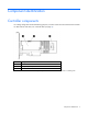
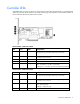
Component identification Controller components For cabling configuration and troubleshooting purposes, connector names are silk-screened on the controller. For LED locations and status, see "Controller LEDs (on page 6)." Item Description 1 Cache module 2 Battery or capacitor pack connector* 3 Internal SAS connector *The 2 GiB cache module connects to a capacitor pack. The 4 GiB cache module connects to a battery pack.
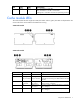
Controller LEDs Immediately after you power up the server, the controller runtime LEDs illuminate briefly in a predetermined pattern as part of the POST sequence. At all other times during server operation, the illumination pattern of the runtime LEDs indicates the status of the controller. P430 controller, 2 GB cache module Item Color Name Interpretation 1 Green Heartbeat When the controller is in good health, this LED flashes at 1 Hz. During power up, this LED is solid for up to 2 seconds.
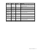
Item Color Name Interpretation 5 Amber Debug On = Controller is in reset state. Off = Controller is in an idle or runtime state. Flashing 5 Hz = Controller and cache are performing a backup. Cache module LEDs The cache module has three single-color LEDs (one amber and two green). The LEDs are duplicated on the reverse side of the cache module to facilitate status viewing.
1 - Amber 2 - Green 3 - Green Interpretation Off On On The cache module is idle, the battery or capacitor pack is charged, and the cache contains data that has not yet been written to the drives. Off Flashing once per second Off A backup of the DDR content on the cache module is in progress. Off On Off The current backup is complete with no errors. Flashing once per second Flashing once per second Off The current backup failed, and data has been lost.
Specifications Memory and storage capacity conventions Memory capacities are specified using binary prefixes: • KiB = 210 bytes • MiB = 220 bytes • GiB = 230 bytes • TiB = 240 bytes Storage capacities are specified using SI prefixes: • KB = 103 bytes • MB = 106 bytes • GB = 109 bytes • TB = 1012 bytes Older, and other, documentation may use SI prefixes for binary values. Actual available memory capacity and actual formatted storage capacity for devices are less than specified values.
Controller features Basic features This HP Smart Array controller has the following basic features: • Supports RAID 0, 1, 10, 1 (ADM), 10 (ADM), 5, 50, 6, and 60 • Advanced Capacity Expansion • Mirror splitting and recombining in offline mode • Drive Erase • Performance optimization for video on demand • Capability for moving and deleting individual LUNs • Split mirror backup and rollback of RAID 1, 10, 1 (ADM) and 10 (ADM) mirrors • Heal Array For more information, see the HP Smart Storage
compatible with HP key manager products and can operate with or without the presence of a key manager in the environment, depending on individual customer settings. HP Secure Encryption provides encryption for data at rest as an important component for complying with data privacy requirements found in government regulations like HIPAA and Sarbanes-Oxley. HP Secure Encryption secures any data deemed sensitive and requiring extra levels of protection through the application of XTS-AES 256-bit data encryption.
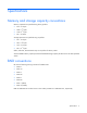
Feature Description Duration of battery 80 seconds or capacitor pack The battery or capacitor pack provides a sufficient duration to transfer the cached data from DDR memory to backup flash memory, where the data remains indefinitely or until a controller retrieves the data. More than 3 years Battery or capacitor pack life expectancy Drives Supported drive types† • • • 6 Gb/s SAS 6 Gb/s SATA 12 Gb/s SAS Not all servers or storage systems support all SAS or SATA drive types.
Installation and configuration Procedures for controllers in a server To install a stand-up controller in a server, choose one of the following procedures: • Installing a stand-up controller in an unconfigured server (on page 13) • Installing a stand-up controller in a previously configured server (on page 13) Installing a stand-up controller in an unconfigured server IMPORTANT: Do not power up the server until the hardware configuration is satisfactory, as described in the procedure given in this sect
3. Verify the server firmware is the latest revision. If necessary, update the server firmware ("Updating firmware" on page 20). 4. Do one of the following: 5. o If the new controller is the new boot device, install the device drivers ("Installing device drivers" on page 20). o If the new controller is not the new boot device, go to the next step. Power down the server.
WARNING: To reduce the risk of personal injury or damage to the equipment, consult the safety information and user documentation provided with the server before attempting the installation. Some servers contain high energy circuits, high current circuits, moving parts (such as fan blades), or any combination of these hazards, that may be exposed if covers and access panels are removed while the product is connected to a power source.
4. o If the drives are hot-plug capable, connect the internal connector of the controller to the SAS connector on the hot-plug drive cage. o If the drives are not hot-plug capable, connect the internal connector of the controller to the non-hot-plug drives. Close or install the access panel, and secure it with thumbscrews, if any are present. CAUTION: Do not operate the server for long periods with the access panel open or removed.
Configuration tools HP Smart Storage Administrator HP SSA is the main tool for configuring arrays on HP Smart Array controllers. It exists in three interface formats: the HP SSA GUI, the HP SSA CLI, and HP SSA Scripting. All formats provide support for configuration tasks. Some of the advanced tasks are available in only one format. The diagnostic features in HP SSA are also available in the standalone software HP Smart Storage Administrator Diagnostics Utility CLI.
UEFI System Utilities At this time, the HP ProLiant DL580 Gen8 Server is the only HP ProLiant Gen8 server that supports UEFI. For servers that support UEFI, the HP UEFI System Utilities is embedded in the system ROM.
2. Perform a normal system shutdown. 3. Restart the server. POST runs, and the system recognizes devices. When the system recognizes the controller you want to set as the boot controller, continue with the next step. 4. Press the F5 key. After POST completes, the system launches the HP SSA GUI, or if you are using Serial Console, the system launches the HP SSA CLI. 5. Select the appropriate menu option, and follow any subsequent on-screen instructions. If prompted to save the settings, do so. 6.
Configuring an array To configure an array on an HP Smart Array controller, use HP SSA. For more information, see the HP Smart Storage Administrator User Guide. Remember the following factors when you build an array: • All drives grouped in a logical drive must be of the same type (for example, either all SAS or all SATA and either all hard drives or all solid state drives). • For the most efficient use of drive space, all drives within an array should have approximately the same capacity.
Managing servers with Insight Agents When using Insight Agents to manage HP ProLiant Gen8 servers, HP recommends that you clear the selection for Agentless Management Service, and then select Insight Agents for installation to take place. You can update the Management Agents by using the latest versions of the agents provided in the Intelligent Provisioning software.
Drive procedures Identifying the status of an HP SmartDrive HP SmartDrives are the latest HP drive technology, and they are supported beginning with ProLiant Gen8 servers and server blades. The HP SmartDrive is not supported on earlier generation servers and server blades. Identify an HP SmartDrive by its carrier, shown in the following illustration. When a drive is configured as a part of an array and connected to a powered-up controller, the drive LEDs indicate the condition of the drive.
Recognizing drive failure If any of the following occurs, the drive has failed: • The drive status LED illuminates amber. • When failed drives are located inside the server or storage system and the drive LEDs are not visible, the Health LED on the front of the server or server blade illuminates. This LED also illuminates when other problems occur such as when a fan fails, a redundant power supply fails, or the system overheats.
Compromised fault tolerance CAUTION: When fault tolerance is compromised, data loss can occur. However, it may be possible to recover the data. For more information, see "Recovering from compromised fault tolerance (on page 24)." If more drives fail than the fault-tolerance method can manage, fault tolerance is compromised, and the logical drive fails. If this failure occurs, the operating system rejects all requests and indicates unrecoverable errors.
Before replacing drives • Open Systems Insight Manager, and inspect the Error Counter window for each physical drive in the same array to confirm that no other drives have any errors. For more information about Systems Insight Manager, see the documentation on the Insight Management DVD or on the HP website (http://www8.hp.com/us/en/products/server-software/product-detail.html?oid=489496#!tab=feat ures ). • Be sure that the array has a current, valid backup.
• Failure of a second drive in a RAID 6 configuration Time required for a rebuild The time required for a rebuild varies, depending on several factors: • The priority that the rebuild is given over normal I/O operations (you can change the priority setting by using HP SSA) • The amount of I/O activity during the rebuild operation • The average bandwidth capability (MBps) of the drives • The availability of drive cache • The brand, model, and age of the drives • The amount of unused capacity on
2. Restore data from backup. Writing data to the location of the unreadable sector often eliminates the error. 3. Remove and reinsert the replacement drive. This action restarts the rebuild process. If the rebuild process still terminates abnormally: 1. Delete and recreate the logical drive. 2. Restore data from backup. Case 2: The replacement drive has failed. Verify that the replacement drive is of the correct capacity and is a supported model.
When data rebuild on the new drive is complete, the Drive status LED changes from flashing green to solid green. 3. Repeat the previous step for the other drives in the array, one at a time. When you have replaced all drives, you can use the extra capacity to either create new logical drives or extend existing logical drives. For more information, see the HP Smart Storage Administrator User Guide on the HP website (http://www.hp.com/go/smartstorage/docs).
o 6. If a 1724 or 1727 POST message appears, drive positions were changed successfully and the configuration was updated. Continue with step 7. If the array did not configure properly, do the following: a. Power down the system immediately to prevent data loss. b. Return the drives to their original locations. c. 7. Restore the data from backup, if necessary. Verify the new drive configuration by running HP SSA ("Configuring an array" on page 20).
When the expansion process has finished, you can use the liberated storage capacity on the enlarged array to create new logical drives. Alternatively, you can use HP SSA to enlarge (extend) one of the original logical drives.
Electrostatic discharge Preventing electrostatic discharge To prevent damaging the system, be aware of the precautions you need to follow when setting up the system or handling parts. A discharge of static electricity from a finger or other conductor may damage system boards or other static-sensitive devices. This type of damage may reduce the life expectancy of the device. To prevent electrostatic damage: • Avoid hand contact by transporting and storing products in static-safe containers.
Regulatory information Safety and regulatory compliance For safety, environmental, and regulatory information, see Safety and Compliance Information for Server, Storage, Power, Networking, and Rack Products, available at the HP website (http://www.hp.com/support/Safety-Compliance-EnterpriseProducts). Belarus Kazakhstan Russia marking Manufacturer Hewlett-Packard Company, Address: 3000 Hanover Street, Palo Alto, California 94304, U.S.
Valid date formats include the following: • YWW, where Y indicates the year counting from within each new decade, with 2000 as the starting point. For example, 238: 2 for 2002 and 38 for the week of September 9. In addition, 2010 is indicated by 0, 2011 by 1, 2012 by 2, 2013 by 3, and so forth. • YYWW, where YY indicates the year, using a base year of 2000. For example, 0238: 02 for 2002 and 38 for the week of September 9.
Support and other resources Before you contact HP Be sure to have the following information available before you call HP: • Active Health System log (HP ProLiant Gen8 or later products) Download and have available an Active Health System log for 3 days before the failure was detected. For more information, see the HP iLO 4 User Guide or HP Intelligent Provisioning User Guide on the HP website (http://www.hp.com/go/ilo/docs).
providers or service partners) identifies that the repair can be accomplished by the use of a CSR part, HP will ship that part directly to you for replacement. There are two categories of CSR parts: • Mandatory—Parts for which customer self repair is mandatory. If you request HP to replace these parts, you will be charged for the travel and labor costs of this service. • Optional—Parts for which customer self repair is optional. These parts are also designed for customer self repair.
Pour plus d'informations sur le programme CSR de HP, contactez votre Mainteneur Agrée local. Pour plus d'informations sur ce programme en Amérique du Nord, consultez le site Web HP (http://www.hp.com/go/selfrepair). Riparazione da parte del cliente Per abbreviare i tempi di riparazione e garantire una maggiore flessibilità nella sostituzione di parti difettose, i prodotti HP sono realizzati con numerosi componenti che possono essere riparati direttamente dal cliente (CSR, Customer Self Repair).
HINWEIS: Einige Teile sind nicht für Customer Self Repair ausgelegt. Um den Garantieanspruch des Kunden zu erfüllen, muss das Teil von einem HP Servicepartner ersetzt werden. Im illustrierten Teilekatalog sind diese Teile mit „No“ bzw. „Nein“ gekennzeichnet. CSR-Teile werden abhängig von der Verfügbarkeit und vom Lieferziel am folgenden Geschäftstag geliefert. Für bestimmte Standorte ist eine Lieferung am selben Tag oder innerhalb von vier Stunden gegen einen Aufpreis verfügbar.
sustituciones que lleve a cabo el cliente, HP se hará cargo de todos los gastos de envío y devolución de componentes y escogerá la empresa de transporte que se utilice para dicho servicio. Para obtener más información acerca del programa de Reparaciones del propio cliente de HP, póngase en contacto con su proveedor de servicios local. Si está interesado en el programa para Norteamérica, visite la página web de HP siguiente (http://www.hp.com/go/selfrepair).
Opcional – Peças cujo reparo feito pelo cliente é opcional. Essas peças também são projetadas para o reparo feito pelo cliente. No entanto, se desejar que a HP as substitua, pode haver ou não a cobrança de taxa adicional, dependendo do tipo de serviço de garantia destinado ao produto. OBSERVAÇÃO: Algumas peças da HP não são projetadas para o reparo feito pelo cliente. A fim de cumprir a garantia do cliente, a HP exige que um técnico autorizado substitua a peça.
Support and other resources 40
Support and other resources 41
Acronyms and abbreviations ADM Advanced Data Mirroring CSR Customer Self Repair FBWC flash-backed write cache FCC Federal Communications Commission FIPS Federal Information Processing Standard HP SSA HP Smart Storage Administrator IML Integrated Management Log LFF large form factor NIST National Institute of Standards and Technology POST Power-On Self Test RBSU ROM-Based Setup Utility SAS serial attached SCSI Acronyms and abbreviations 42
SATA serial ATA SFF small form factor SMH System Management Homepage SPP HP Service Pack for ProLiant UEFI Unified Extensible Firmware Interface Acronyms and abbreviations 43
Documentation feedback HP is committed to providing documentation that meets your needs. To help us improve the documentation, send any errors, suggestions, or comments to Documentation Feedback (mailto:docsfeedback@hp.com). Include the document title and part number, version number, or the URL when submitting your feedback.
Index A adding drives 29 array, configuring 20 authorized reseller 34 automatic data recovery (rebuild) 25 B battery replacement notice 32 battery warranty 33 before you contact HP 34 boot controller, setting 18 boot options 18, 19 BSMI notice 32 C cable part numbers 16 cache module LEDs 7 Canadian notice 32 components 5 components, controller 5 compromised fault tolerance 24 configuration procedures 18 configuration tools 17 configuration utilities 17 configuring an array 20 connecting internal storage 1
J T Japanese notice 32 Taiwan battery recycling notice 32 technical support 34 telephone numbers 34 time required for a rebuild 26 L LEDs, cache module 7 LEDs, controller 6 limited warranty 33 load protection guarantee 33 M memory capacity convention 9 methods for updating firmware 20 modifications, FCC notice 32 moving an array 28 moving drives 28 U UEFI System Utilities 18 unconfigured server, installation in 13 updating firmware 20 upgrading drive capacity 27 W warranty information 33 website, HP