HP B-series 16Gb FC Switches Hardware Reference Guide Abstract This document provides information on installing, configuring, and maintaining the HP StoreFabric SN6500B 16Gb Fibre Channel Switch, the HP SN6000B 16Gb Fibre Channel Switch, and the HP SN3000B 16Gb Fibre Channel Switch. It is intended for system administrators and technicians with knowledge of SANs and HP FC switches.
© Copyright 2011, 2014 Hewlett-Packard Development Company, L.P. © Copyright 2011, 2014 Brocade Communications Systems, Incorporated Confidential computer software. Valid license from HP required for possession, use or copying. Consistent with FAR 12.211 and 12.212, Commercial Computer Software, Computer Software Documentation, and Technical Data for Commercial Items are licensed to the U.S. Government under vendor's standard commercial license.
Contents 1 HP 16Gb FC switches.................................................................................6 HP StoreFabric SN6500B 16Gb FC Switch..................................................................................6 Overview............................................................................................................................6 Platform capabilities.............................................................................................................
Setting the date............................................................................................................38 Setting the time zone.....................................................................................................39 Synchronizing local time................................................................................................40 Synchronizing local time using NTP.................................................................................
FC port specifications..............................................................................................................69 Serial port specifications..........................................................................................................70 AG default port mapping........................................................................................................70 B Regulatory information..............................................................................
1 HP 16Gb FC switches This chapter provides general information about the HP StoreFabric SN6500B 16Gb FC Switch, HP SN6000B 16Gb FC Switch, and HP SN3000B 16Gb FC Switch. NOTE: For descriptions of acronyms and abbreviations used in this guide, see the “Glossary”. HP StoreFabric SN6500B 16Gb FC Switch This section provides an overview of the HP StoreFabric SN6500B 16Gb FC Switch. It describes platform capabilities and components, the physical layout of the switch, and hardware and software options.
• FC ports self-configure as E_Ports and F_Ports. EX_Ports can be activated on a per-port basis with the optional Integrated Routing license. ◦ M_Ports and D_Ports must be configured manually. ◦ The D_Port feature provides physical media diagnostic, troubleshooting, and verification services. • In-flight data compression and encryption on up to four ports provide efficient link utilization and security. • VF support improves isolation between VFs.
• One 2 GB compact flash card • Up to 96 16 Gb/s FC ports • One USB 2.
Figure 2 Nonport side of HP SN6500B StoreFabric 16Gb FC Switch 1. Power supplies with integral fans 2.
Hardware options Table 1 Optional hardware kits Hardware kit Part number HP OM3 LC-LC Optical Cables 0.5m HP OM3 LC/LC Multi-mode Optical Cable AJ833A 1m HP OM3 LC/LC Multi-mode Optical Cable AJ834A 2m HP OM3 LC-LC Multi-mode Optical Cable AJ835A 5m HP OM3 LC-LC Multi-mode OM3 Optical Cable AJ836A 15m HP OM3 LC-LC Multi-mode OM3 Optical Cable AJ837A 30m HP OM3 LC-LC Multi-mode OM3 Optical Cable AJ838A 50m HP OM3 LC-LC Multi-mode OM3 Optical Cable AJ839A HP PremierFlex OM3+ Optical Cables 0.
HP SN6000B 16Gb FC Switch This section provides an overview of the HP SN6000B 16Gb FC Switch. It describes platform capabilities and components, the physical layout of the switch, and hardware and software options. Overview The HP SN6000B 16Gb FC Switch is a 48-port autosensing 4, 8, 10, or 16 Gb/s FC switch that delivers the latest HP single-chip architecture for FC SANs.
• ISL Trunking (licensable), which allows up to eight ports (at 4, 8, or 16 Gb/s) between a pair of switches combined to form a single, logical ISL with a speed of up to 128 Gb/s (256 Gb/s full duplex) for optimal bandwidth utilization and load balancing. • DPS, which optimizes fabric-wide performance and load balancing by automatically routing data to the most efficient available path in the fabric.
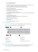
Figure 3 Port side of the HP SN6000B 16Gb FC Switch 1. System status LED 2. Management Ethernet port with LEDs 3. USB port 4. FC ports (0-3) 5. FC ports (40-43) 6. FC ports (44-47) 7. FC ports (4-7) 8. Switch ID pull-out tab 9. Serial console port 10. System power LED NOTE: The two LEDs on the serial console port are nonfunctional.
◦ Advanced Performance Monitor ◦ Fabric Vision Software1 • Extended Fabric • Fabric Watch • Advanced Performance Monitor • ISL Trunking • Integrated Routing • HP SN6000B 10Gb Integrated FC Extension (enables 10Gb FC for first eight ports) • SN6000B 16Gb 24-48 12-port FC Upgrade LTU NOTE: For the latest information on supported software components, see the product QuickSpecs available from the HP website: http://www.hp.com/go/sn6000b/quickspecs.
Hardware options Table 3 Optional hardware kits Hardware kit Part number HP OM3 LC-LC Optical Cables 0.5m HP OM3 LC/LC Multi-mode Optical Cable AJ833A 1m HP OM3 LC/LC Multi-mode Optical Cable AJ834A 2m HP OM3 LC-LC Multi-mode Optical Cable AJ835A 5m HP OM3 LC-LC Multi-mode OM3 Optical Cable AJ836A 15m HP OM3 LC-LC Multi-mode OM3 Optical Cable AJ837A 30m HP OM3 LC-LC Multi-mode OM3 Optical Cable AJ838A 50m HP OM3 LC-LC Multi-mode OM3 Optical Cable AJ839A HP PremierFlex OM3+ Optical Cables 0.
HP SN3000B 16Gb FC Switch This section provides an overview of the HP SN3000B 16Gb FC Switch. It describes platform capabilities and components, the physical layout of the switch, and hardware and software options. Overview The HP SN3000B 16Gb FC Switch is a 24-port autosensing 4, 8, or 16 Gb/s FC switch that delivers the latest HP single-chip architecture for FC SANs.
Services include Adaptive Networking with QoS, Extended Fabrics, Enhanced Group Management, Fabric Watch, ISL Trunking, and APM. • Support for AG configuration where server ports connected to the fabric core will be virtualized. • Hardware zoning is accomplished at the port level of the switch and by WWN. Hardware zoning permits or denies delivery of frames to any destination port address. • Extensive diagnostics and system-monitoring capabilities for enhanced RAS.
5. System power LED 6. Serial console port 7. Switch ID pull-out tab 8. FC ports (4–7) NOTE: The two LEDs on the serial console port are nonfunctional. Nonport side of the switch Figure 7 (page 18) shows the nonport side of the SN3000B 16Gb Switch. Figure 7 Nonport side of the HP SN3000B 16Gb FC Switch 1. Filler panel (Optional Power supply and fan assembly can be added in this slot) 2. Power supply and fan assembly #1 3. Power supply and fan assembly LED 4. On/off switch 5.
For example, the FC ports on the SAN Switch are numbered from left to right and color-coded in groups of eight to indicate which ports you can combine into trunking groups. Figure 8 (page 19) shows the switch with three trunking groups of eight ports. NOTE: If your switch is licensed for ISL Trunking, use the trunking groups available on the switch. Figure 8 HP SN3000B 16Gb FC Switch trunking groups example 1. Trunking group 1: Ports 0–7 2. Trunking group 2: Ports 8–15 3.
Table 5 Optional hardware kits (continued) Hardware kit Part number 30m HP PremierFlex OM4 LC/LC Multi-mode Optical Cable QK736A 50m HP PremierFlex OM4 LC/LC Multi-mode Optical Cable QK737A NOTE: For the latest information on supported hardware components, see the product QuickSpecs available from the HP website: http://www.hp.com/go/sn3000b/quickspecs.
2 Installing and configuring HP 16Gb FC switches This chapter provides installation and configuration information for the HP 16Gb FC switches. Accessories The following items are included with the standard shipment of a fully-configured HP 16Gb FC Switch.
• A maximum of 71.36 cubic meters/hour (42 cubic feet/minute). Nominal airflow is 59.47 cubic meters/hour (35 cubic feet/minute). • The primary AC input follows: ◦ HP SN6000B 16Gb FC Switch and HP SN3000B 16Gb FC Switch 85–264 VAC Nominal: 100–240 VAC, 2.0 A; 47–63 Hz. The switch autosenses input voltage. ◦ HP StoreFabric SN6500B 16Gb FC Switch AC input is 90–264 VAC, Nominal: 100–240 VAC, 12.0 A–5.0 A; 47–63 Hz. The switch autosenses input voltage.
Installing the switch This section provides instructions for installing the HP StoreFabric SN6500B 16Gb FC Switch, HP SN6000B 16Gb FC Switch, and HP SN3000B 16Gb FC Switch.
Table 7 SAN Switch Rack Mount Kit hardware Item Description Two rear mounting brackets A right inner rail and a right outer rail A left inner rail and a left outer rail 14 #8-32 x 5/16-inch Phillips panhead SEMS screws for use with the HP StoreFabric SN6500B 16Gb FC Switch. This switch requires 10 screws.
NOTE: For switches with Port Side Air Intake, attach the rear mounting brackets to the front rack uprights. • For an HP 10000 Series Rack, assemble each of the brackets using two #10-32 x 1/2-inch Phillips panhead screws with captive star lock washers and two #10 adapter washers, as shown in Figure 9 (page 25). • For an HP System/e Rack, install the two rear mounting brackets using two 8-32 x 5/16-inch Phillips panhead SEMS screws and two #10 alignment washers, as shown in Figure 10 (page 25).
NOTE: The SAN Switch Rack Mount Kit contains rails labeled Left and Right to designate the left side and right side of the switch or cabinet, as viewed from the front of the cabinet.
4. Assemble the outer rails as follows: NOTE: For switches with Port Side Air Intake, attach Left outer rail to the right side of the rack and Right outer rail to the left side of the rack. a. Attach the left outer rail and right outer rail to the rear mounting brackets using two 1/4-20 hex with captive star lock washers attached loosely, as shown in Figure 11 (page 27). Do not tighten the nuts. Figure 11 Installing the outer rails (HP 10000 Series Rack) b.
• For an HP System/e Rack, install two #10-32 x 1/2-inch Phillips panhead screws with captive star lock washers and two #10 alignment washers in the upper and lower holes on the right rail. Then, install two #10-32 x 1/2-inch panhead screws with captive star lock washers and two #10 alignment washers in the upper and lower holes on the left rail. See Figure 13 (page 28). Figure 13 Assembling the outer rails (HP System/e Rack) 5.
Figure 14 Attaching the inner rails to the switch Securing the switch to the outer rails 1. 2. Insert the switch with the attached inner rails into the outer rails. Insert the switch into the rack and install one #10-32 x 1/2-inch Phillips panhead screw with captive star lock washer. Repeat for the other side. See Figure 15 (page 29) and Figure 16 (page 30).
Figure 16 Securing the switch (HP System/e Rack) 3. 4. Tighten the hex nuts installed in stepStep 4. Verify that the switch power and status LEDs on the port side of the switch are green. See Figure 17 (page 30). Figure 17 LEDs on port side 5. 1. System power LED 2. System status LED 3. FC port status LED (port 0) 4. FC port status LED (port 4) 5. Ethernet port activity LED 6. Ethernet port speed LED Proceed to “Setting up the switch” (page 36). This completes the rack mount procedure.
Installing the HP SN6000B 16Gb FC and HP SN3000B 16Gb FC switches in a rack using the Rack Mount Kit Use the SN6000B and the SN3000B Switch Rack Mount Kits to install the switch in an HP 10000 Series Rack. CAUTION: Install the Rack Mount Kits as described in this section so that when the switch is installed, the port side faces the rear of the rack. This configuration optimizes performance in the following ways: • Provides better airflow by using a plenum.
Rack mount installation To install the switch in a rack using the Rack Mount Kit: 1. Place the switch on a flat surface and attach each inner rail to the switch using three flat-head screws. See Figure 18 (page 32). The rails are labeled Left and Right to designate the left side and right side of the switch as viewed from its nonport side. Figure 18 Attaching the inner rails to the switch 2. 3.
4. Attach each outer rail as shown in Figure 20 (page 33). The rails are labeled Left and Right to designate the left side and right side of the rack as viewed from the front of the cabinet. NOTE: For switches with Port Side Air Intake, attach Left outer rail to the right side of the rack and Right outer rail to the left side of the rack. Figure 20 Attaching the outer rails a. b. c. Slide each rail over the rear mounting brackets.
5. Install the switch. See Figure 21 (page 34). a. From the front of the rack, slide the switch (with inner rails attached) onto the outer rails, taking care to align the inner rails with the attachment screws on the outer rails at the rear of the rack. b. When the switch is in place, secure the inner rails to the outer rails by tightening the screws at the rear of the rack. Figure 21 Installing the switch in the rack 6.
Figure 22 Connecting power and installing the plenum 7. 1. Cutouts for power cords 3. Power switches 2. Power cable plugs 4. Plenum thumb screws Connect the other end of the power cords to power sources on separate circuits to protect against AC failure. (Make sure that two power cords are connected to the SN6000B 48-port switch and one power cord is connected to the SN3000B 24–port switch.
Figure 24 Port side status LEDs 1. System power LED 2. System status LED Installing a standalone switch 1. 2. Unpack the switch and verify the contents, as described in Shipping carton contents. Apply the adhesive rubber feet to prevent the switch from sliding off the supporting surface. a. Clean the indentations at each corner on the bottom of the switch to ensure that they are free of dust or other debris. b.
• Disk array with FC ports • Browser that allows pop-up windows • If you are using static IP addressing, you will need the following items (not required if using DHCP): ◦ Fixed IP address (IPv4 or IPv6) for the switch ◦ Subnet mask value ◦ Default gateway value Connecting the serial cable 1. Connect the serial cable to the serial port on the switch and to an RS-232 serial port on the workstation.
Using DHCP to set the IP address When using DHCP, the switch obtains its IP address, subnet mask, and default gateway address from the DHCP server. The DHCP client can connect only to a DHCP server that is on the same subnet as the switch. If your DHCP server is not on the same subnet as the switch, use a static IP address. Setting a static IP address 1. Use the ipaddrset command to set the Ethernet IP address. • For an IPv4 address, use dotted-decimal notation: switch :admin> ipaddrset 192.168.74.
2. Enter the date command: date "mmddHHMMyy" The values are as follows: • mm is the month; valid values are 01 through 12. • dd is the date; valid values are 01 through 31. • HH is the hour; valid values are 00 through 23. • MM is minutes; valid values are 00 through 59. • yy is the year; valid values are 00 through 99. (Values greater than 69 are interpreted as 1970 through 1999; values less than 70 are interpreted as 2000-2069.
1. 2. Log in to the switch using the default password password. Use timezone_fmt to set the time zone by Country/City or by time zone ID, such as PST. The following example shows how to change the time zone to US/Central: switch:admin> tstimezone Time Zone : US/Pacific switch:admin> tstimezone US/Central switch:admin> tstimezone Time Zone : US/Central The following procedure sets the time zone to Pacific Standard Time using interactive mode: 1.
2. Enter the tsclockserver command: switch:admin> tsclockserver "” The value ntp1 is the IP address or DNS name of the first NTP server, which the switch must be able to access. The value ntp2 is the name of the second NTP server and is optional. The entire operand "” is optional; by default, this value is LOCL, which uses the local clock of the principal or primary switch as the clock server. switch:admin> tsclockserver LOCLx switch:admin> tsclockserver "132.163.135.
1. Install the SFP+ transceivers in the FC ports on the switch to match the ports displayed in the Device Connection window . If you are using an SFP+ transceiver that does not have a pull tab, ensure that the wire bail is in the unlocked position. See Figure 25 (page 42). NOTE: Each SFP+ transceiver has a 10-pad gold-plated PCB-edge connector on the bottom. Insert an SFP+ transceiver into the upper row of ports with the gold edge down.
2. Connect the FC cables from the switch to your host and storage devices. Ensure that the physical connections match the connections displayed in the Device Connection window. a. Remove the plastic protector caps from the FC cable ends (if there are any) and position the cable connector so that it is oriented correctly. b. Position a cable so that the key (the ridge on one side of the cable connector) is aligned with the slot in the transceiver (see Figure 26 (page 42)). c.
Verifying the configuration To confirm that the switch is configured and ready for use: 1. Observe the LEDs to verify that all components are functional. For information about LED patterns, see “LEDs” (page 47). 2. Issue the switchshow command from the workstation. This command provides information about the switch and port status. 3. Issue the fabricshow command from the workstation. This command provides general information about the fabric.
6. Optional: Enter the portshow command to verify that the newly activated ports have started. Fabric OS Native and AG modes The switch can function in either Fabric OS Native mode or AG mode. The switch is shipped in Native mode by default. • You can enable AG mode using Fabric OS commands or Web Tools. • All POD licenses must be installed before you enable AG mode.
Enabling AG mode Note the following when enabling AG mode: • After you enable AG mode, some fabric information is erased, such as the zone and security databases. • Enabling AG mode is disruptive because the switch is disabled and rebooted. • Ensure that no zoning or AD transaction buffers are active. If a transaction buffer is active, enabling AG mode fails with the error Failed to clear Zoning/Admin Domain configuration. To enable AG mode using Fabric OS commands: 1.
3 Operating HP 16Gb FC switches This chapter discusses switch power, LEDs, maintenance, and management. Powering the switch on and off • Power switches are located on the nonport side of the switch. • If either the HP SN3000B or SN6000B 16Gb FC switch is mounted in a rack, you must remove the plenum to access the power switches. • Power is supplied to the switch as soon as the first power supply is connected and powered on.
Figure 28 LEDs on nonport side of the StoreFabric SN6500B 16Gb FC Switch 1. Power supply DC status LED 2. Power supply AC status LED 3. Fan status LED Table 8 LED patterns on the nonport side of the HP StoreFabric SN6500B 16Gb FC Switch LED name Status of hardware Recommended action Power No light supply/AC input status (one green LED) Steady green Power supply is not receiving AC input voltage or AC input voltage is below the operational limit.
Table 9 LED patterns on the port side of the HP StoreFabric SN6500B, SN6000B, and SN3000B 16Gb FC switches LED name LED color Status of hardware Recommended action System power (green) No light System is off or there is an internal power supply failure. Verify that the system is powered on (power supply switches set to I), the power cables are attached, and the power source is live. The unit may be faulty. Contact your switch service provider.
Table 9 LED patterns on the port side of the HP StoreFabric SN6500B, SN6000B, and SN3000B 16Gb FC switches (continued) LED name LED color Status of hardware Recommended action Fast blinking green (1/2 second) Internal loopback (diagnostic). No action is required. Flickering green The port is online, with frames flowing through the port. No action is required. Figure 29 Port side of the HP SN6000B and SN3000B 16Gb FC switches 1. System power LED 2. System status LED 3.
Table 10 LED patterns on the nonport side of the HP SN6000B and SN3000B 16Gb FC switches LED name LED color Status of hardware Recommended action Power supply and fan assembly status No light Power supply/fan assembly is not receiving power or is off. Verify that the power supply/fan assembly is on and seated and the power cord is connected to a functioning power source. Steady green Power supply/fan assembly is operating normally. No action is required.
• Analyzing the fabric. If any ports are connected to other switches, the switch participates in a fabric configuration. • Obtaining a domain ID and assigning port addresses. • Constructing unicast routing tables. • Enabling normal port operation. Switch maintenance The switch supports only HP-branded 8 Gb/s and 16 Gb/s SFP+ optical transceivers. For the FC connections, the switch uses SFP+ transceivers that support any combination of SWL, LWL, and ELWL optical media.
Table 11 Switch management tools Management tool Out-of-band support In-band support CLI Ethernet or serial connection IP over FC Ethernet or serial connection IP over FC Ethernet or serial connection IP over FC Ethernet or serial connection Native in-band interface (over HBA only) Ethernet or serial connection IP over FC Up to two admin sessions and four user sessions simultaneously. See the Fabric OS Administrator’s Guide and the Fabric OS 7.0.x Command Reference Manual.
Determining the need to replace a power supply Use one of the following methods to determine the status of the power supplies: • Check the power supply AC status and DC status LEDs; both should be green. See “LEDs” (page 47) for more information. If the DC status LED is amber, there is no power running through the cord. • In Web Tools, click the Power Status icon.
• If one fan fails, the remaining fans go to high speed to maintain proper cooling until the failed fan is replaced. • If a mismatched power supply or fan assembly is installed by mistake, a critical error message is sent to the console. The message will be similar to the following: CRITICAL HIL-1611 MISMATCH in PSU/FAN Air Flow direction. Replace PSU with fan air flows in same direction. System will be shut down in 2 minutes.
5. Plug the power cord into the power supply to power on the unit. If the power was on before the replacement, the power supply will attempt to power up immediately. Figure 32 Inserting the power supply in the HP StoreFabric SN6500B 16Gb FC Switch 6. Verify that the LEDs on the new power supply are steady green when the switch is operating. See Table 8 (page 48) for more information. If the LEDs are not steady green, ensure that the power supply is installed securely.
Determining the need to replace a fan Use one of the following methods to determine the status of the fans: • Check the fan status LED. See “LEDs” (page 47) for more information. • In Web Tools, click the Power Status icon. • At the command prompt, enter the fanShow command to display the fan status. NOTE: Fans 4 and 5 are integral to the power supplies. These fans typically operate at approximately 12,000 RPM; while the system fans typically operate at approximately 2,000 RPM.
a. b. Verify that the airflow direction is the same as that of the fan you are replacing. Orient the new fan with the captive screw on the right, as shown in Figure 34 (page 58). CAUTION: c. d. • Do not force the power supply into the chassis. If the fan does not slide in easily, ensure that it is oriented correctly before continuing. • After replacing a fan, if the switch powers down after 2 minutes, it is probably because the new fan has a mismatched airflow.
NOTE: When replacing the power supply and fan assembly in an HP SN3000B 16Gb FC Switch that has only one, the switch must be powered off prior to replacing the assembly. Figure 35 (page 59) shows the power supply and fan assemblies on the nonport side of a switch with two assemblies. The standard HP SN3000B 16Gb FC Switch includes a single power supply and fan assembly. Fabric OS identifies the assemblies from right to left as assemblies 1 and 2.
3. Power off the power supply to be replaced by setting the AC power switch to the off (O) position. The fans in the other power supply automatically switch to high speed to maintain adequate cooling. 4. 5. 6. 7. Unplug the power cord from the power supply and fan assembly being replaced. Unscrew the captive screw using a Phillips screwdriver. Remove the power supply and fan assembly by pulling the handle out and away from the chassis.
Installing a power supply and fan assembly To install the power supply and fan assembly: 1. Ensure that the replacement FRU AC power switch is in the off (O) position. CAUTION: Damage to the switch can result if the AC power switch is in the on (|) position when the switch is installed in the chassis. 2. Orient the new power supply and fan assembly with the captive screw on the right, as shown in Figure 36 (page 60). CAUTION: Do not force the assembly into the chassis.
4 Support and other resources Contacting HP For worldwide technical support information, see the HP Support Center: http://www.hp.
• http://www.hp.com/support/manuals • http://www.hp.com/support/downloads Typographic conventions Table 12 Document conventions Convention Element Blue text: Table 12 (page 63) • Cross-reference links and e-mail addresses • A cross reference to the glossary definition of the term in blue text Blue, bold, underlined text email addresses Blue, underlined text: http://www.hp.
5 Documentation feedback HP is committed to providing documentation that meets your needs. To help us improve the documentation, send any errors, suggestions, or comments to Documentation Feedback (docsfeedback@hp.com). Include the document title and part number, version number, or the URL when submitting your feedback.
A Specifications This appendix provides switch specifications. Physical specifications Table 13 HP StoreFabric SN6500B 16Gb FC Switch physical specifications Dimension Value Height 86.74 mm (3.415 in) Depth 609.75 mm (24.006 in) Width 429.25 mm (16.900 in) Weight (with two power supplies and three fan assemblies, 16.9 kg (37.3 lb) and no transceivers installed) Table 14 HP SN6000B and SN3000B 16Gb FC switches physical specifications Dimension Value Height 1U or 4.3 cm (1.
Power supply specifications The power supplies are universal and operate worldwide without voltage jumpers or switches. They meet IEC 61000-4-5 surge voltage requirements and support autoranging to accommodate input voltages and line frequencies. Each power supply has built-in fans for cooling. Table 16 HP StoreFabric SN6500B 16Gb FC Switch power supply specifications Specification Values Input voltage Range: 90–264 VAC Auto-volt, Nominal: 100–240 VAC, 12.0-5.
Table 19 HP StoreFabric SN6500B 16Gb FC Switch environmental requirements Condition Acceptable range during operation Acceptable range during nonoperation Ambient temperature 0º to 40ºC (32º to 104ºF) -25º to 70ºC (-13º to 158ºF) Humidity 10% to 85% RH noncondensing, at 40ºC (104ºF) 10% to 90% RH noncondensing, at 70ºC (158ºF) Altitude 0 to 3 km (9,842 ft) above sea level 0 to 12 km (39,370 ft) above sea level Shock 20 G, 6 ms, half-sine wave 33 G, 11 ms, half-sine wave, 3/e.g.
Table 22 HP SN6000B 16Gb FC Switch general specifications Specification Description Configurable port types F_Port, E_Port, M_Port, EX_Port, and D_Port System architecture Nonblocking shared-memory switch System processor PowerPC 440EPx at 667 MHz ANSI FC protocol FC-PH Modes of operation FC Class 2 and Class 3 Fabric initialization Complies with FC-SW-3 Rev. 6.6 FC-IP Complies with FC-IP 2.
Table 24 HP StoreFabric SN6500B 16Gb FC Switch supported optics, speeds, cables, and distances (SFP+) (continued) Transceiver type LWL Speed Multimode media Multimode Multimode media Multimode (62.5 microns) media (50 (50 microns) media (50 (OM1) microns) (OM2) (OM3) microns) (OM4) Single Mode Media (9 microns) 4 Gb/s N/A N/A N/A N/A 30 km (18.6 mi) 8 Gb/s N/A N/A N/A N/A 10 km (6.2 mi) 40 km (24.8 mi) ELWL 1 10 Gb/s N/A N/A N/A N/A 10 km (6.2 mi) 16 Gb/s N/A N/A N/A N/A 10 km (6.
The FC ports meet all required safety standards. For more information about these standards, see “Regulatory information” (page 72). The ports operate at 2, 4, 8, or 16 Gb/s, depending on SFP+ models, and are able to autonegotiate to the maximum link speed. NOTE: HP does not support 2 Gb/s connectivity to the HP StoreFabric SN6500B 16Gb FC Switch, HP SN6000B 16Gb FC Switch, or HP SN3000B 16Gb FC Switch.
Table 29 HP SN3000B 16Gb FC Switch AG default port mapping (continued) Total ports F_Ports N_Ports Default port mapping 6, 7 mapped to 19 8, 9 mapped to 20 10, 11 mapped to 21 12, 13 mapped to 22 14, 15 mapped to 23 AG default port mapping 71
B Regulatory information This appendix contains regulatory notices for the HP B-series 16Gb FC Switches. For important safety, environmental, and regulatory information, see Safety and Compliance Information for Server, Storage, Power, Networking, and Rack Products, available at http:// www.hp.com/support/Safety-Compliance-EnterpriseProducts.
C Electrostatic discharge and grounding recommendations Electrostatic discharge recommendations CAUTION: To prevent damaging the system, be aware of the precautions you need to follow when setting up the system or handling parts. A discharge of static electricity from a finger or other conductor may damage system boards or other static-sensitive devices. This type of damage can reduce the life expectancy of the device.
Glossary This glossary defines acronyms and terms used in this guide or related to this product. It is not a comprehensive glossary of computer terms. AD Admin Domain. AG Access Gateway. APM Advanced Performance Monitoring. CUP Control Unit Port. D_Port Diagnostic port. DDR2 Double data rate 2. DHCP Dynamic Host Configuration Protocol. DPOD Dynamic Ports on Demand. DPS Dynamic Path Selection. DWDM Dense wavelength-division multiplexing. ECC Error-correcting code.
SEEPROM Serial Electrically Erasable Programmable Read Only Memory. SFP Small Form-Factor Pluggable. SNMP Simple Network Management Protocol. SWL Short Wavelength. UTC Coordinated Universal Time. VF Virtual Fabric. WWN World Wide Name.
Index platform components, 7 port side, 8 software options, 9 C commands licenseadd, 44 licenseshow, 44 portenable, 44 portshow, 44, 45 portstart, 44 contacting HP, 62 conventions document, 63 text symbols, 63 customer self repair, 63 I installing and configuring the switch, 21 ISL trunking groups HP SN3000B 16Gb FC Switch, 18 HP SN6000B 16Gb FC Switch, 14 L licenseadd command, 44 licenseshow command, 44 D O document conventions, 63 related information, 62 documentation HP website, 62 providing feedba
W warranty information HP Enterprise servers, 72 HP Networking products, 72 HP ProLiant and X86 Servers and Options, 72 HP Storage products, 72 web sites HP subscription service, 62 websites, 62 customer self repair, 63 product manuals, 62 77