HP Direct-Connect External SAS Storage for HP BladeSystem Solutions Deployment Guide This document provides device overview information, installation best practices and procedural overview, and illustrated examples for attaching external 3G SAS storage enclosures to an HP BladeSystem c-Class enclosure. The BladeSystem solutions described in this guide include a BladeSystem c-Class enclosure with server blades, 3G SAS Smart Array controllers, 3Gb SAS switch blades, and 3Gb SAS external storage enclosures.
© Copyright 2008, 2013 Hewlett-Packard Development Company, L.P. Confidential computer software. Valid license from HP required for possession, use or copying. Consistent with FAR 12.211 and 12.212, Commercial Computer Software, Computer Software Documentation, and Technical Data for Commercial Items are licensed to the U.S. Government under vendor's standard commercial license. The information contained herein is subject to change without notice.
Contents I Solution devices and concepts.......................................................................6 1 Introduction............................................................................................9 Topics discussed in this guide..............................................................................................10 Devices referred to in this deployment guide..........................................................................
High availability / dual domain information.............................................49 5 Zoning information...............................................................................50 Types of zone groups.........................................................................................................50 Key zoning configuration steps............................................................................................50 Zoning requirements and device mappings.........................
MDS600 single domain, high-performance cabling................................................................94 MDS600 single domain, high-performance cabling, max performance with SATA drives.............95 MDS600 dual domain, standard cabling..............................................................................97 MDS600 dual domain, high-performance cabling..................................................................98 MDS600 with two c-Class enclosures.......................................
Part I Solution devices and concepts
Contents 1 Introduction...............................................................................................9 Topics discussed in this guide...................................................................................................10 Devices referred to in this deployment guide...............................................................................10 Documents referred to in this deployment guide..........................................................................
4 High availability / dual domain information................................................49 5 Zoning information...................................................................................50 Types of zone groups..............................................................................................................50 Key zoning configuration steps.................................................................................................50 Zoning requirements and device mappings........
1 Introduction This document provides guidelines, instructions, and illustrated examples to help deploy a solution centered around a BladeSystem c-Class enclosure with server blades, 3Gb SAS controllers, 3Gb SAS switch blades, and 3Gb external SAS storage enclosures. MSL Tape Libraries and Tape Autoloaders are also discussed.
Topics discussed in this guide • General descriptions and primary features of devices in a BladeSystem solution with external SAS storage enclosures • Links to essential installation, setup, and user instructions for each device • Information about high availability and performance • Information about different zoning techniques and scenarios • Summary of the fundamental steps required to successfully deploy a BladeSystem solution with external SAS storage enclosures • Configuration and cabling e
• HP 2000 Modular Smart Array Racking Instructions • HP 2000 Modular Smart Array Family Installation Road Map • HP 2000sa Modular Smart Array Supported Cable Configurations • HP 2012sa Modular Smart Array User Guide • HP 2000 Modular Smart Array Family Reference Guide • HP 2000 Family Modular Smart Array CLI Reference Guide • HP 2000 Family Modular Smart Array Firmware Upgrade Instructions MSA2000sa G2 storage enclosures: • HP 2000 Modular Smart Array racking instructions • HP 2000 Modular Sm
◦ Sign up for driver and support alerts (strongly recommended) ◦ Customer advisories ◦ Customer notices Information available in the BladeSystem Technical Resources website Some of the tasks you can perform in the BladeSystem documentation page (http://www.hp.com/ go/bladesystem/documentation) include the following: • In the initial display, access and read conceptual documents and architectural overviews of the HP BladeSystem environment.
Getting started To help you successfully deploy this solution in your environment, be sure to do the following: • Locate a workstation with a CD/DVD-ROM drive and access to the Internet, for reading component-specific user documents from the CD/DVD or HP website associated with the component. • Prepare the site for the power and cooling needs of the solution and its components. (See the user documents for your c-Class BladeSystem Enclosure.
2 Device information Overview information is provided for the following solution devices: • “HP BladeSystem c-Class Enclosures” (page 14) • “HP BladeSystem c-Class server blades” (page 17) • “HP Smart Array P700m Controller” (page 19) • “HP 3Gb SAS BL Switch” (page 22) • “HP 600 Modular Disk System” (page 25) • “HP 2000sa G2 Modular Smart Array” (page 28) • “HP 2000sa Modular Smart Array” (page 32) • “HP MSL2024, MSL4048, and MSL8096 Tape Libraries and 1/8 G2 Tape Autoloader” (page 35) • “R
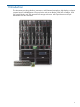
HP BladeSystem c3000 enclosure The HP BladeSystem c3000 is built specifically for small-size deployment environments without requiring special power and cooling capabilities. It provides eight device bays and four interconnect bays in a 6U rack-mount or tower-mount configuration. For more information Device website: http://h18004.www1.hp.com/products/blades/components/enclosures/c-class/ c3000/ BladeSystem Technical Resources website: http://www.hp.
HP BladeSystem c7000 enclosure The HP BladeSystem c7000 enclosure is ideal for larger data centers with more dynamic data center environments. It provides 16 device bays and 8 interconnect bays in a 10U rack-mount configuration. For more information Device website: http://h18004.www1.hp.com/products/blades/components/enclosures/c-class/ c7000/ BladeSystem Technical Resources website: http://www.hp.
HP BladeSystem c-Class server blades An HP c-Class server blade is a full-function server that slides into an HP BladeSystem c-Class enclosure, in contrast to a server that is mounted in a rack. One great advantage of blade architecture is the easy removal and addition of more server blades to your environment. HP BladeSystem c-Class enclosures support server blade models that are built in standardized form factors, referred to as half-height (4U) or full-height (8U).
Be sure to read the following documents, shipped with the server blade and BladeSystem enclosure: • HP ProLiant Server Blade Installation Instructions—Includes physical installation instructions. • HP BladeSystem c-Class Solution Overview Setup Poster—Provides an overview of the complete installation process of an HP BladeSystem c-Class solution.
HP Smart Array P700m Controller The HP P700m Controller (P700m) is a PCI-Express SAS Smart Array card that supports external shared storage for c-Class enclosures. In BladeSystem solutions using the 3Gb SAS BL Switch, one or more P700m can be installed on each HP ProLiant server blade. (Two are installed on double-density server blades; one on each server node.
For more detailed information about the controller, see the following documents, available on HP websites: • HP Smart Array P700m Controller for HP ProLiant Servers User Guide—Includes detailed hardware description and user information Important tips • In zoned solutions such as those using the MDS600 storage enclosure, the 512 MB model HP P700m Controller is required. In addition, for RAID 6 support, the battery option kit is required.
Device mappings for the c7000 BladeSystem enclosure: BladeSystem c-Class enclosure model Server type c7000 Half height nl Mezzanine slot BladeSystem c-Class server device bay BladeSystem c-Class interconnect bay 1 Any 3/4 2 Any 5/6/7/8 1 Any 3/4 2 Any 5/6/7/8 1A – 8A 5/6 nl nl nl nl Full height nl nl 3 Half height Double dense (BL2x220c) “A-side” nl 9A – 16A nl “B-side” 1B – 8B 7/8 9B – 16B Full height Double wide (BL680c G7) 1 Any 3/4 2 Any 5/6/7/8 5 Any 3/4 7
HP 3Gb SAS BL Switch The HP 3Gb SAS BL Switch (HP 3Gb SAS BL Switch) is HP's first c-Class embedded SAS switch designed to provide external storage for HP c-Class server blades.
For more information Device website: http://h18006.www1.hp.com/products/storageworks/3gbsas_switch/index.html BladeSystem Technical Resources website: http://www.hp.com/go/bladesystem/documentation Be sure to read the following documents, shipped with the switch and BladeSystem enclosure: • HP 3Gb SAS BL Switch Installation Instructions—Includes physical installation instructions.
For more information about single domain, dual domain, and high performance 8x cabling, see “Deployment examples” (page 92). • 24 When the c7000 enclosure is populated with double-density server blades, four switches can be installed in BladeSystem c-Class interconnect bays 5, 6, 7, and 8. ◦ Switches in interconnect bays 5 and 6 map to the “a” server nodes in device bays 1–16. (Referred to as servers 1A–16A.) ◦ Switches in interconnect bays 7 and 8 map to the “b” server nodes in device bays 1–16.
HP 600 Modular Disk System The HP 600 Modular Disk System (MDS600) is a Serial Attach SCSI (SAS) storage enclosure. The MDS600 supports 3.5" SAS or Serial ATA (SATA) drives and attaches to HP BladeSystem c7000 or c3000 enclosures via the HP 3Gb SAS BL Switch. The MDS600 has two, 35-drive drawers for a total of 70 drives. IMPORTANT: Drives greater than 2 TB are not supported for use when the MDS600 is connected to the HP 3Gb SAS BL Switch in a 3G direct-connect external SAS storage solution.
Single domain environments with SATA drives: Include one Dual domain environments with dual-port SAS drives: I/O module in each storage enclosure drawer. Include two I/O modules in each storage enclosure drawer. For more information Device website: http://www.hp.com/go/mds600 BladeSystem Technical Resources website: http://www.hp.
• • When connecting power cords, consider the following: ◦ The MDS600 storage enclosure, BladeSystem c-CLass enclosure, and other devices in the rack all consume power. Make sure that sufficient power input is available. ◦ Each MDS600 storage enclosure ships with two pairs of unique power cords ◦ The offset power cord option kit (AF502B) is available for use with the MDS600 storage enclosure.
HP 2000sa G2 Modular Smart Array The HP 2000sa G2 Modular Smart Array (MSA2000sa G2) is 3Gb SAS, external shared storage that helps users easily transition from direct attached to centralized storage. It allows departmental and small-to-medium businesses grow capacity as demands increase. The MSA2000sa G2 allows mixing of enterprise-class, dual-port SAS drives and archival-class single-port SATA drives, and supports both Large Form Factor and Small Form Factor drives.
NOTE: MSA2000 G2 is a family name for a collection of second-generation MSA2000 models. • MSA2012sa G2 refers to the 12 drive bay, 3.5-inch drive SAS controller enclosure. • MSA2024sa G2 refers to the 24 drive bay, 2.5-inch drive SAS controller enclosure. • MSA2300sa G2 refers to the SAS controller that can be used in either G2 controller enclosure. • MSA2000 refers to the drive enclosure that can connect to the MSA2012sa or MSA2024sa controller enclosure for additional storage capacity.
Configuration, management, and monitoring tasks are performed using the Storage Management Utility (SMU) or Command Line Interface (CLI), both of which are embedded in MSA2000–family array controller firmware. For more information about these software utilities, see “Software information” (page 38). Functionality of the two user interfaces is similar, but presented in different console formats. HP recommends becoming familiar with and primarily using one of the two interfaces.
• • The controller and its storage are configured using the Storage Management Utility (SMU) or Command Line Interface (CLI). ◦ For information about configuring storage in the SMU, see the HP 2000 G2 Modular Smart Array reference guide. ◦ For information about configuring storage in the CLI, see the HP 2000 G2 Modular Smart Array CLI reference guide. (Optional but strongly recommended) Map each MSA2000sa storage volume to ports on the server blades. This is called explicit mapping.
HP 2000sa Modular Smart Array NOTE: The HP 2000sa Modular Smart Array is no longer available for purchase, but is supported for use in BladeSystem solutions using the 3Gb SAS BL Switch and P700m Controller. The HP 2000sa Modular Smart Array (MSA2000sa) is modular, reliable, affordable, and easy-to-manage external shared SAS storage enclosure. MSA2000 storage enclosures provide twelve drive bays able to accommodate 3.5-inch enterprise-class dual-port SAS drives or archival-class single-port SATA drives.
• Ability to grow as storage demands increase. The MSA2000sa controller enclosure can support up to three cascaded drive enclosures. For detailed information about maximum-capacity configurations, see the MSA2000sa QuickSpecs. • Choice of high performance enterprise class dual-port SAS drives or low cost, high capacity archival class single-port SATA drives.
• • The MSA controller and its drives are configured using the Storage Management Utility (SMU) or Command Line Interface (CLI). ◦ For information about configuring storage in the SMU, see the HP 2000 Family Modular Smart Array reference guide. ◦ For information about configuring storage in the CLI, see the HP 2000 Family Modular Smart Array CLI reference guide. (Optional but strongly recommended) Map each MSA2000sa storage volume to ports on the server blades. (This is called explicit mapping.
HP MSL2024, MSL4048, and MSL8096 Tape Libraries and 1/8 G2 Tape Autoloader The HP MSL2024, MSL4048, and MSL8096 Tape Libraries and 1/8 G2 Tape Autoloader provide compact, high-capacity, low-cost solutions for simple, unattended data backup. The Libraries house 12 tape cartridges for each 1U of height, with easy access to tape cartridges via removable magazines and one or more mailslots.
For more information about configuration guidelines, see the EBS Design Guide. • SAS tape libraries must be connected to a port on an HP 3Gb SAS BL Switch (they cannot be connected to a SAS port on an MSA or MDS storage enclosure). • Each SAS tape drive has a single SAS port. Redundancy is not supported, so the host end of the fanout cable will be connected to only one port on one HP 3Gb SAS BL Switch. Either HP 3Gb SAS BL Switch in the BladeSystem c-Class enclosure may be used.
Rack and Power HP helps companies manage power and cooling costs. HP provides a variety of hardware and software, enabling optimal deployment of HP servers and storage, and smarter control over power, cooling and access. For more information For additional information see the following HP websites: HP Infrastructure products website: http://h18004.www1.hp.com/products/servers/platforms/ rackandpower.
3 Software information The following software tools are used to configure, manage, and monitor devices in this solution: 38 • “HP Onboard Administrator” (page 39) • “HP Virtual SAS Manager” (page 42) • “MSA2000-family Storage Management Utility” (page 43) • “MSA2000-family Command Line Interface” (page 44) • “HP Array Configuration Utility” (page 45) • “HP Systems Insight Manager” (page 46) • “MSL Tape Libraries and 1/8 G2 Tape Autoloader remote management interface” (page 47) • “MSL Tape L
HP Onboard Administrator HP BladeSystem Onboard Administrator (OA) is the enclosure management processor, subsystem, and firmware base used to support the HP BladeSystem c-Class enclosures and the managed devices contained within the enclosure. OA provides a single point from which to view the entire HP BladeSystem c-Class environment and perform basic management tasks on BladeSystem devices, including server blades and switches installed in the c-Class enclosure.
Selecting an item in the OA navigation tree displays management and monitoring tasks for the selected device. For example, when an SAS BL Switch installed in interconnect bay 6 is selected in the navigation tree, additional information about the device is displayed, with tabs at the top of the display providing additional functions.
To determine installed firmware versions of components, click Rack Firmware in the navigation tree. The display shows all BladeSystem devices, along with the currently-installed and latest-available firmware versions.
HP Virtual SAS Manager HP Virtual SAS Manager (VSM) is embedded in the HP 3Gb SAS BL Switch firmware and is the software application used to create hardware-based zone groups to control access to external SAS storage. Servers in the c-Class enclosure are then granted access to these zone groups, allowing them to access the storage.
MSA2000-family Storage Management Utility The Storage Management Utility (SMU) offers a graphical user interface (GUI) for configuring, managing, and monitoring the MSA2000-family storage systems. The SMU is accessed through a browser by entering the IP address of the MSA2000 management port.
MSA2000-family Command Line Interface The embedded CLI offers a command level method of configuring, managing, and monitoring the MSA2000-family array and its storage. You can enter individual commands or command scripts.
HP Array Configuration Utility The Array Configuration Utility (ACU) is a host-based, browser-accessed tool for configuring, managing, and monitoring MDS600 storage. The ACU is supported for use in Windows, Linux, and NetWare environments and can run locally from the server or remotely through HP Systems Insight Manager (HP SIM). The ACU: • Is available in both a graphical user interface and a command line interface. • Allows the setting of access rights to MSA storage by hosts.
HP Systems Insight Manager HP Systems Insight Manager (SIM) is the foundation for the HP unified server-storage management strategy. SIM is a hardware-level management product that provides basic management features through a single management view. SIM provides device management capabilities that consolidate and integrate management data from HP and third-party devices. SIM reports hardware fault conditions (both failure and pre-failure) and collects data for reporting and graphing.
MSL Tape Libraries and 1/8 G2 Tape Autoloader remote management interface With the remote management interface (RMI), you can monitor, configure, and operate most Library or Autoloader functions from a web browser. The RMI is accessed through a browser by entering the IP address of the Library or Autoloader.
MSL Tape Libraries and 1/8 G2 Tape Autoloader operator control panel The operator control panel (OCP) has a power button, four LEDs, an LCD screen, and control keys. With the OCP, you can monitor, configure, and operate most Library or Autoloader functions from the front panel. Use the control buttons to scroll through the menu. For more information about the OCP, see the HP MSL2024, MSL4048, and MSL8096 Tape Library user and service guide or the HP 1/8 G2 Tape Autoloader user and service guide.
4 High availability / dual domain information HP External SAS BladeSystem Solutions provide high availability, offering c-Class BladeSystem users full connectivity to External SAS storage by using the following redundant hardware components: • Two controllers in each MSA2000sa controller enclosure • Two I/O modules in each MDS600 storage enclosure drawer (four per MDS600 storage enclosure) • Two HP 3Gb SAS BL Switches in each BladeSystem c-Class enclosure (four when using double-density server blades i
5 Zoning information HP Virtual SAS Manager (VSM) is the software application used to configure the switch, and create and manage hardware-based zone groups. These zone groups allocate resources for device load balancing purposes and for selectively allowing access to data. For planning purposes, zone groups and assignments can be pre-configured, even if servers or drives are not yet installed in BladeSystem c-Class enclosure device bays or storage enclosure drive bays.
Zoning requirements and device mappings Tables in this section show the device mappings and subsequent zoning requirements of solution devices: • BladeSystem c-Class enclosure model • Server type (half height, full height, half height double density, and full height double wide) • Mezzanine slot (P700m location) • BladeSystem c-Class enclosure server device bay (server blade location) • BladeSystem c-Class enclosure interconnect bay (switch blade location) • 3Gb SAS BL Switch port to which the ex
Zoning requirements for the c7000 BladeSystem enclosure: BladeSystem c-Class enclosure model Server type c7000 Half height nl Mezzanine slot BladeSystem c-Class enclosure server device bay BladeSystem c-Class enclosure interconnect bay Zone groups must be in storage enclosures connected to these 3Gb SAS BL Switch ports 1–8 3/4 1–4 9 – 16 3/4 5–8 1–8 5/6/7/8 1–4 9 – 16 5/6/7/8 5–8 1 Any 3/4 1–4 2 Any 5/6/7/8 1–4 3 Any 5/6/7/8 5–8 “A-side” 1A – 8A 5/6 1–4 9A – 16A 5/6 5–
c-Class device bay numbers: Switch port numbers: As shown in the previous tables, each 3Gb SAS BL Switch is organized in two sets of connections. These two connection sets are based on the two SAS expanders housed in the switch. Each SAS expander provides four external SAS ports and is connected internally to eight blade bays. This design creates the restrictions on configuration best practices.
When creating a zone group: • When creating a drive bay based zone group, all the drives in the zone group should be attached to the switch through the same set of four ports shown in the table. For example, a zone group could include drives from three storage enclosures attached to ports 1, 3, and 4. However, creating a zone group using drives from two storage enclosures attached to ports 1 and 5 is not supported.
Part II Installation, maintenance, and troubleshooting
Contents 6 Installation notes and best practices............................................................57 BladeSystem c-Class enclosure installation notes and best practices...............................................57 Server blade installation notes and best practices.......................................................................57 HP P700m Controller installation notes and best practices............................................................
6 Installation notes and best practices BladeSystem c-Class enclosure installation notes and best practices • The BladeSystem c-Class enclosure can be installed in a rack or rack-free environment. • Before installing components in the BladeSystem c-Class enclosure, be sure to review enclosure device bay and interconnect bay numbering. • Before installing components in the BladeSystem c-Class enclosure, be sure understand which mezzanine slots on which servers map to which interconnect bay.
HP 3Gb SAS BL Switch installation notes and best practices • When selecting a BladeSystem interconnect bay for the switch, make sure that the selected interconnect bay maps to the desired server blade. For more information, see “Zoning requirements and device mappings” (page 51). • Both switches in an interconnect bay row of the BladeSystem c-Class enclosure must be the same model. For example, both switches must be 3Gb SAS BL Switches.
◦ During the updating process, firmware on the primary and secondary MDS600 I/O modules are automatically updated (assuming both I/O modules are attached to a pair of SAS switches in the same BladeSystem interconnect row.) ◦ For more information about updating MDS600 firmware, see the HP3G Virtual SAS Manager User Guide.
7 Installation steps This section provides an overview of the steps required to install a BladeSystem enclosure with external SAS storage; details are not included in the scope of this document. For details, see the setup and installation instructions provided with each device. User documents for devices in this solution are available on the HP Manuals website http://www.hp.com/support/manuals and on the device websites: BladeSystem Technical Resources website: http://www.hp.
Key installation steps Step 1 Set up the rack. Step 3 Install P700m controller on each server blade. Step 4 and Step 5 Install BladeSystem c-Class enclosure and its servers, interconnect devices, and other components. Install operating system updates and patches, and, if necessary, update firmware. Step 6 For each server that will boot locally (not use the storage enclosure as a boot device), install the operating system. Step 7 Install MDS600 storage enclosures. If necessary, update the firmware.
Installation steps 1. 2. 3. Set up the rack and its power distribution units (PDUs). If applicable, install the Tape Library or Autoloader. Install one or more P700m controller on each server blade. For detailed instructions on installing the P700m, see the HP Smart Array P700m Controller Installation Overview and HP Smart Array P700m Controller for HP ProLiant Servers User Guide. Make sure to install the P700m controller in a mezzanine slot that maps to planned interconnect bays of the switches.
configuring the BladeSystem enclosure, the Insight Display verifies that there are no installation or configuration errors. g. h. 5. Complete the Onboard Administrator First Time Setup Wizard. (See the HP BladeSystem Onboard Administrator user guide.) Record additional important system information about each device in the BladeSystem c-Class enclosure in the spaces provided in “Solution summary worksheet” (page 68) “Server and P700m controller worksheet” (page 69), and “SAS BL Switch worksheet” (page 70).
For more information about cabling storage enclosures to the switch, see “Deployment examples” (page 92). g. h. Connect the power cords. Apply power to the MDS600 storage enclosures. Confirm successful startup of the MDS600 storage enclosure. View the LEDs on the front and rear of each MDS600 to monitor the progress of the POST. For more information about MDS600 LED patterns, see “Component identification” in the HP 600 Modular Disk System User Guide. i.
j. k. storage enclosures, see “Updating firmware on MSA2000sa controller and drive enclosures” (page 79). Install required MSA-specific drivers and software, such as the multipathing Device Specific Module, on each server that will access the MSA2000sa. (See “Host System Requirements” in the MSA2000 user guide and MSA2000sa QuickSpecs.) Connect SAS cables from the MSA2000sa controller enclosure to the switch.
worksheet” (page 69). These WWN are used in the SMU or CLI when granting hosts access to the storage. The WWNs of all P700m ports connected to each HP 3Gb SAS BL Switch are displayed as “Device ID” on the Switch Port Mapping page in Onboard Administrator. (See the HP Onboard Administrator user guide.) c. Create Vdisks and volumes using the SMU or CLI.
8 Device worksheets Use the following worksheets to record important reference information about your devices. Because the number of devices differ for each installation, print or copy pages as needed.
Solution summary worksheet Use the following spaces to record big-picture information about your solution. This information might be required or obtained during initial setup and configuration, and is helpful for future configuration changes and troubleshooting.
Server and P700m controller worksheet Server blade model: Serial number: Server name: OS version/service pack: Installed in enclosure device bay number: Onboard Administrator IP address: Mezzanine slot used by HP P700m Controller: P700m serial number P700m firmware version (must be the same on all controllers): P700m WWN Accessing switch in interconnect bay # Server and P700m controller worksheet 69
SAS BL Switch worksheet IMPORTANT: Dual-domain configurations need two switches.
MDS600 storage enclosure worksheet Model: MDS600 storage enclosure Chassis serial number: Device name: Firmware version (must be the same on all I/O modules): I/O module 1 WWID: I/O module 2 WWID: I/O module 3 WWID: I/O module 4 WWID: ACU login information: Drive types and sizes: MDS600 storage enclosure worksheet 71
MSA2000sa controller enclosure worksheet Model: MSA2000sa controller enclosure MSA controller model: Chassis serial number: Device name: Drive type and size: Firmware version (must be the same on both controllers): Controller A Management port IP address: Controller A, Port 0 WWN: Controller A, Port 1 WWN: Controller B Management port IP address: Controller B, Port 0 WWN: Controller B, Port 1 WWN: SMU login information: 72 Device worksheets
MSA2000 drive enclosure worksheets Model: MSA2000 drive enclosure Chassis serial number: Device name: Enclosure firmware version: Drive type and size: Model: MSA2000 drive enclosure Chassis serial number: Device name: Enclosure firmware version: Drive type and size: Model: MSA2000 drive enclosure Chassis serial number: Device name: Enclosure firmware version: Drive type and size: Model: MSA2000 drive enclosure Chassis serial number: Device name: Enclosure firmware version: Drive type and size: MSA2000 dr
MSA70 drive enclosure worksheets Model: MSA70 drive enclosure Chassis serial number: Device name: Enclosure firmware version: Drive type and size: Model: MSA70 drive enclosure Chassis serial number: Device name: Enclosure firmware version: Drive type and size: Model: MSA70 drive enclosure Chassis serial number: Device name: Enclosure firmware version: Drive type and size: Model: MSA70 drive enclosure Chassis serial number: Device name: Enclosure firmware version: Drive type and size: 74 Device worksheet
Tape and Autoloader worksheet Model: Chassis serial number: Device name: Firmware version: Tape and Autoloader worksheet 75
9 Maintenance and troubleshooting Included sections: • “Updating firmware on solution devices” (page 76) • “Troubleshooting” (page 79) Updating firmware on solution devices As part of a routine system maintenance program, periodically check firmware versions installed on all devices in your solution. Updated firmware may include additional features and functions, performance enhancements, support for newly released hardware, or fixes to known issues.
Updating firmware on HP 3Gb SAS BL Switches HP 3Gb SAS BL Switch firmware updates can be performed using the Smart Update Firmware DVD ISO or the HP Virtual SAS Manager (VSM) utility. Smart Update Firmware DVD ISO and Firmware Release Sets— These tools deliver tested, compatible sets of firmware for components included in BladeSystem solutions and are designed to help manage firmware interdependencies between HP BladeSystem Components. These tools use executable Smart Component firmware packages.
7. In single-domain configurations, schedule a maintenance window and do the following to prepare for restarting the switch: a. Stop host traffic. b. Power off servers that map to this switch. c. Power off storage enclosures connected to the switch. 8. Restart the switch. From the VSM Maintain tab, select the switch that was just updated, and then click Reset Hardware. During the reset process, you are automatically logged out of VSM. 9. Wait a few minutes for the switch to reset. 10.
3. 4. 5. 6. 7. 8. 9. 10. From the workstation with access to both the firmware file and the BladeSystem c-Class enclosure, access the VSM for the Active (or Not Redundant) switch. Click the refresh icon to ensure that you are viewing the most recent status information and correct any issues before proceeding. In the VSM, select the Maintain tab, and then click Update Storage Enclosure Firmware. Expand the Reset enclosures after update drop-down box and select Yes.
• Obtain System Event Logs from software tools, such as Onboard Administrator, Virtual SAS Manager, the Storage Management Utility, and Array Configuration Utility. • Obtain the ADU report. Troubleshooting the HP 3Gb SAS BL Switch Problem Solution Amber LED on Switch • Check OA and VSM for status alerts to identify the problem. • See the HP 3Gb SAS BL Switch User Guide for LED definitions.
Part III Deployment examples
Contents 10 Introduction............................................................................................83 11 Device SAS port information.....................................................................85 HP 3Gb SAS BL Switch port information....................................................................................85 MDS600 disk enclosure port information...................................................................................
10 Introduction Examples in this section illustrate a few of the supported deployments when connecting external SAS storage enclosures to the c-Class BladeSystem. The focus of these examples is on hardware options, requirements, and SAS cabling. Most examples are of dual-domain, high-availability configurations, so that if any component along the path fails, traffic will fail over to the alternate path.
The following standards are maintained in the sample configurations: Device Single domain Dual domain SAS switches: Depending on the type of server blade used, one or two switches are installed in the c-Class enclosure, providing a single path between the server blades and the switches. When using full-height or half-height server blades, one switch is required.
11 Device SAS port information HP 3Gb SAS BL Switch port information As shown in the following illustration: • SAS ports: Eight per switch. Labeled 1–8 from left to right on the front of the switch. Use these SAS ports to connect external SAS storage enclosures and tape devices. When cabling external storage enclosures to the switch, note the following: • Storage enclosures connected to switch ports 1–4 are reserved for use by server bays 1–8 in the BladeSystem c-Class enclosure.
MDS600 disk enclosure port information As shown in the following illustration: • Drawer numbers: The MDS600 has two drawers that contain the drives. From the rear of the device, drawer number 1 is on the right. • SAS Ports: Each MDS600 I/O module has two SAS ports. Use these SAS ports to connect to the 3Gb SAS BL Switch.
MSA2000sa G2 controller enclosure port information As shown in the following illustration: • SAS host ports: Four per controller. Labeled SAS 1, SAS 2, SAS 3, and SAS 4. Use these SAS host ports to connect to the hosts (switch). When two controllers are installed in the enclosure, the controllers are referred to as follows: • ◦ Top controller: A, with host ports referred to as A1, A2, A3, and A4. ◦ Bottom controller: B, with host ports referred to as B1, B2, B3, and B4.
MSA2000sa controller enclosure port information As shown in the following illustration: • SAS host ports: two per controller. Labeled SAS Port 0 and SAS Port 1. Use these SAS host ports to connect to the hosts (switch). When two controllers are installed in the enclosure, the controllers are referred to as follows: • 88 ◦ Top controller: A, with host ports referred to as A0 and A1 ◦ Bottom controller: B, with host ports referred to as B0 and B1 SAS expansion port: one per controller.
MSA2000 drive enclosure port information MSA2000 drive enclosures are supported for use in MSA2000sa and MSA2000sa G2 environments. As shown in the following illustration: • SAS In port: One, on the left-side of the I/O module. Labeled SAS, with a round symbol at the bottom of the label. Use this SAS expansion port to connect to an MSA controller enclosure or to an MSA2000 drive enclosure that is between this drive enclosure and the controller enclosure.
MSA70 drive enclosure port information MSA2000 drive enclosures are supported for use in MSA2000sa G2 environments. As shown in the following illustration: • SAS In port: one, on the left-side of the I/O module. Use this SAS expansion port to connect to an MSA2000sa G2 controller enclosure or to an MSA2000 or MSA70 drive enclosure that is between this drive enclosure and the controller enclosure. • SAS Out port: one, on the right-side of the I/O module.
12 External SAS device, controller, drive, and cabling support matrices External SAS device, controller, and drive support matrix The following table provides a matrix for external SAS devices, showing the supported SAS controllers. Supported drive types are also indicated.
13 Deployment examples The following example deployments are illustrated: 92 • “MDS600 single domain, standard cabling” (page 93) • “MDS600 single domain, high-performance cabling” (page 94) • “MDS600 single domain, high-performance cabling, max performance with SATA drives” (page 95) • “MDS600 dual domain, standard cabling” (page 97) • “MDS600 dual domain, high-performance cabling” (page 98) • “MDS600 with two c-Class enclosures” (page 99) • “MDS600 maximum capacity” (page 100) • “MDS600 w
MDS600 single domain, standard cabling This example illustrates standard cabling for a single-domain configuration using single-port SATA drives. In this configuration, note the following: • One cable from each MDS600 I/O module to the switch offers single-domain connectivity.
MDS600 single domain, high-performance cabling This example illustrates high-performance cabling for a single-domain configuration using single-port SATA drives. In this configuration, note the following: • An additional cable from each MDS600 I/O module to an adjacent port on the switch offers additional performance: one cable provides a 4x connection; two cables provide a 8x connection. For more information on switch ports, 4x, and 8x (high-performance cabling, see “HP 3Gb SAS BL Switch” (page 22).
MDS600 single domain, high-performance cabling, max performance with SATA drives This example illustrates cabling for best-possible performance in a single-domain configuration using single-port SATA drives. In this configuration, note the following: • This configuration combines a unique cabling scheme AND zone group creation strategy to achieve best possible performance in a single-domain configuration.
Devices and quantities MDS600 storage enclosures: 2 MDS600 I/O modules in each MDS600: 2 BladeSystem c7000 enclosures: 1 3Gb SAS BL Switches: 2 Server blade types: half-height and full-height Connection details • Switch in interconnect bay 5: ◦ Port 1: to MDS600 drawer 2, primary I/O module, port 1 ◦ Port 2: to MDS600 drawer 2, primary I/O module, port 2 ◦ Port 5: to MDS600 drawer 2, primary I/O module, port 1 ◦ Port 6: to MDS600 drawer 2, primary I/O module, port 2 • Switch in interconnect bay 6:
MDS600 dual domain, standard cabling This example illustrates standard cabling for a high-availability configuration when using dual-port SAS drives. In this configuration, note the following: • One cable from each MDS600 I/O module to each switch offers high availability.
MDS600 dual domain, high-performance cabling This example illustrates cabling for an optimal high-performance, high-availability configuration when using dual-port SAS drives. In this configuration, note the following: • An additional cable from each MDS600 I/O module to an adjacent port on the switch offers additional performance: one cable provides a 4x connection; two cables provide a 8x (high-performance) connection.
MDS600 with two c-Class enclosures This example illustrates cabling from two BladeSystem c-Class enclosures to one MDS600 storage enclosure. In this configuration, note the following: • This example shows a dual-domain MDS600 with high-performance cabling. Dual-domain standard cabling and single-domain devices are also supported.
MDS600 maximum capacity This example illustrates the maximum number of MDS600 storage enclosures that can be connected to a c7000 BladeSystem enclosure when housed in a 42U rack. In this configuration, note the following: • This example shows a dual-domain MDS600 with standard cabling.
Devices and quantities MDS600 storage enclosures: 6 MDS600 I/O modules: 4 per MDS600 BladeSystem c7000 enclosures: 1 3Gb SAS BL Switches: 4 Server blade types: half-height Connection details • Due to space limitations and level of detail, connection details are not listed.
MDS600 with double-density servers These examples illustrates two recommended cabling configurations when using double-density server blades with zoned storage enclosures such as the MDS600. In this configuration, note the following: • These examples show dual I/O module MDS600 and high-performance cabling. Single I/O modules and standard cabling is also supported.
• Switches in interconnect bays 5 and 6 map to the “a” server nodes in device bays 1–16. (Referred to as servers 1a–16a.) • Switches in interconnect bays 7 and 8 map to the “b” server nodes in device bays 1–16. (Referred to as servers 1b–16b.
MSA2000 single controller, standard cabling This example illustrates standard cabling for a single-controller MSA2000sa enclosure. In this configuration, note the following: • One cable from the switch to the MSA controller offers single-path connectivity. NOTE: Features of the MSA2000sa and MSA2000sa G2 differ, but cabling and configuration concepts are the same. This cabling scenario showing the MSA2000sa may also be applied to the MSA2000sa G2.
MSA2000 dual controller, standard cabling This example illustrates standard cabling for a high-availability configuration. In this configuration, note the following: • One cable from each switch to each MSA controller offers high availability. NOTE: Features of the MSA2000sa and MSA2000sa G2 differ, but cabling and configuration concepts are the same. This cabling scenario showing the MSA2000sa may also be applied to the MSA2000sa G2.
MSA2000 dual controller, dual domain optimal cabling This example illustrates optimal cabling for a high-performance, high-availability configuration. In this configuration, note the following: • An additional cable from each switch to each MSA controller offers additional availability and performance. • Connecting each controller to each switch ensures highest availability. NOTE: Features of the MSA2000sa and MSA2000sa G2 differ, but cabling and configuration concepts are the same.
MSA2000sa G2 dual controller, optimal cabling This example illustrates optimal cabling for a high-performance, high-availability configuration. In this configuration, note the following: • An additional cable from each switch to each MSA controller offers additional availability and performance. • Connecting each controller to each switch ensures highest availability.
MSA2000 with cascaded drive enclosures This example expands on the cabling paths illustrated in “MSA2000 dual controller, dual domain optimal cabling” (page 106) and shows connection paths from a dual-controller MSA2012sa controller enclosure to cascaded, dual I/O module MSA2000 drive enclosures. NOTE: Features of the MSA2000sa and MSA2000sa G2 differ, but cabling and configuration concepts are the same. This cabling scenario showing the MSA2000sa may also be applied to the MSA2000sa G2.
MSA2000sa G2 with two c-Class enclosures, This example illustrates cabling from two BladeSystem c-Class enclosures to one MSA2300sa controller enclosure. In this configuration, note the following: • This example shows a dual-controller MSA2300sa controller enclosure with optimal cabling. Standard cabling is also supported. Standard cabling offers high availability, but, during a failover, there will be a slight performance reduction.
MSA2000 maximum capacity This example illustrates the maximum number of supported MSA2000sa controller enclosures and cascaded MSA2000 drive enclosures that can connect to a c7000 BladeSystem enclosure housed in a 42U rack. • A maximum of four MSA2000sa (or MSA2000sa G2) controller enclosures can be attached to a BladeSystem c-Class enclosure. • The MSA2000sa can support a maximum of three MSA2000 drive enclosures (the MSA2000sa G2 can support a maximum of four MSA2000 drive enclosures.
MSA2000 with double-density servers This example illustrates recommended cabling when using double-density server blades with shared storage enclosures such as the MSA2000sa. In this configuration, note the following: • This example shows a dual-controller MSA2012sa controller enclosure and standard cabling. MSA2300sa controller enclosures (standard and optimal cabling) and single-controller devices are also supported.
Devices and quantities MSA2012sa controller enclosures: 2 MSA2000 drive enclosures: 6 c7000 enclosures: 1 3Gb SAS BL Switches: 4 Server blade types: double-density Connection details • Switch in interconnect bay 5: ◦ Port 1: to MSA #2, SAS port A0 ◦ Port 2: to MSA #1, SAS port A0 • Switch in interconnect bay 6: ◦ Port 1: to MSA #2, SAS port B0 ◦ Port 2: to MSA #1, SAS port B0 • Switch in interconnect bay 7: ◦ Port 1: to MSA #2, SAS port A1 ◦ Port 2: to MSA #1, SAS port A1 • Switch in intercon
MDS600 and MSA2000 G2 to the same c-Class enclosure This example illustrates cabling from one BladeSystem c-Class enclosure to both an MSA2000sa G2 controller enclosure and an MDS600 storage enclosure. In this type of configuration, note the following: IMPORTANT: • In a solution with both zoned and shared storage enclosures, a server bay can be assigned to either zoned or shared zone groups. (Cannot be assigned to both types of storage enclosures.
Notes • As shown in this illustration, server bays 1–8 may access MDS600 drawer 2 and server bays 9–16 may access MDS600 drawer 1. For more information, see “HP 3Gb SAS BL Switch port information” (page 85).
Tape library standard cabling The purpose of this example is to show cabling to a tape library. IMPORTANT: The following illustration shows an MSA2012sa in the configuration, but tape autoloaders and tape libraries are supported with shared SAS storage enclosures and zoned SAS storage enclosures.
Part IV Support and other resources
Contents 14 Support and other resources...................................................................118 Contacting HP......................................................................................................................118 Before you contact HP......................................................................................................118 HP contact information.....................................................................................................
14 Support and other resources Contacting HP Before you contact HP Be sure to have the following information available before you call or contact HP: • Technical support registration number (if applicable) • Product serial number • Product model name and number • Product identification number • Applicable error message • Add-on boards or hardware • Third-party hardware or software • Operating system type and revision level HP contact information For the name of the nearest HP authorized rese
Document conventions and symbols Convention Element Blue text: Document conventions and symbols Cross-reference links and e-mail addresses Blue, underlined text: http://www.hp.
Customer self repair HP customer self repair (CSR) programs allow you to repair your product. If a CSR part needs replacing, HP ships the part directly to you so that you can install it at your convenience. Some parts do not qualify for CSR. Your HP-authorized service provider will determine whether a repair can be accomplished by CSR. For more information about CSR, contact your local service provider, or see the CSR website http:// www.hp.com/go/selfrepair.
Index Symbols 3Gb SAS BL Switch information about, 22 installation best practices, 58 port information, 85 worksheets, 70 A ACU reference documents, 11 Array Configuration Utility (ACU) configuring the storage, 45 overview, 45 B best practices installation, 60 installing 3Gb SAS BL Switch , 58 installing BladeSystem enclosures, 57 installing MDS600 enclosures, 58 installing MSA2000sa enclosures, 59 installing P700m cards, 57 installing server blades, 57 zoned cabling, 51 BladeSystem installation best prac
I P installation 3Gb SAS BL Switch best practices, 58 BladeSystem best practices, 57 key steps of, 61 MDS600 best practices, 58 MSA2000sa best practices, 59 overview, 60 P700m best practices, 57, 58 server blade best practices, 57 steps of, 62 P700m information about, 19 installation best practices, 57 worksheets, 69 port information 3Gb SAS BL Switch, 85 MDS600 disk enclosure, 86 MSA2000 drive enclosure, 89 MSA2000sa controller enclosure, 88 MSA2000sa G2 controller enclosure, 87 MSA70 drive enclosure, 9
T tape devices example cabling, 115 information about, 35 worksheets, 75 technical support HP, 118 text symbols, 119 troubleshooting 6Gb SAS BL Switch, 80 MDS600, 80 two c-Class enclosures to shared storage, 109 to zoned storage, 99 V Virtual SAS Manager (VSM) overview, 42 VSM reference documents, 11 W warning rack stability, 120 websites available tasks in, 11 customer self repair, 120 HP Subscriber's Choice for Business, 118 list of, 12 product manuals, 11 worksheets, 67 3Gb SAS BL Switch, 70 MDS600, 71