Service Manual hp StorageWorks 1000ux/1900ux/2300ux and 3800ux/7100ux Optical Jukebox Second Edition (September 2004) Part Number: AA969-90904 This guide describes procedures for removing and replacing FRUs, and troubleshooting the HP StorageWorks 1000ux/1900ux/2300ux and 3800ux/7100ux Optical Jukebox.
© Copyright 2004 Hewlett-Packard Development Company, L.P. Hewlett-Packard Company makes no warranty of any kind with regard to this material, including, but not limited to, the implied warranties of merchantability and fitness for a particular purpose. Hewlett-Packard shall not be liable for errors contained herein or for incidental or consequential damages in connection with the furnishing, performance, or use of this material.
Contents Contents About this Guide. . . . . . . . . . . . . . . . . . . . . . . . . . . . . . . . . . . . . . . . . . . . . . . . . . . . . . . . . . . . . . . 5 Related documentation . . . . . . . . . . . . . . . . . . . . . . . . . . . . . . . . . . . . . . . . . . . . . . . . . . . . . . . . . . . . . . . . . . . . .6 Conventions . . . . . . . . . . . . . . . . . . . . . . . . . . . . . . . . . . . . . . . . . . . . . . . . . . . . . . . . . . . . . . . . . . . . . . . . . . . . .
Contents 3 FRU Removal and Replacement . . . . . . . . . . . . . . . . . . . . . . . . . . . . . . . . . . . . . . . . . . . . . . . . . . . 61 FRU Removal and Replacement for 1000ux/1900ux/2300ux Models. . . . . . . . . . . . . . . . . . . . . . . . . . . . . . . .62 Replacing a Power Supply . . . . . . . . . . . . . . . . . . . . . . . . . . . . . . . . . . . . . . . . . . . . . . . . . . . . . . . . . . . . . .63 Replacing the Mailslot Assembly . . . . . . . . . . . . . . . . . . . . . . . . . . . . .
About this Guide About this Guide This service manual provides information to help you: ■ Troubleshoot the jukebox. About this Guide ■ Remove and replace Field Replaceable Units (FRUs).
About this Guide Related documentation In addition to this guide, HP provides corresponding information: For 1000ux/1900ux/2300ux models: ■ The HP StorageWorks 1000ux/1900ux/2300ux Optical Jukebox Getting Started Poster provides an installation overview. ■ The HP StorageWorks 1000ux/1900ux/2300ux Optical Jukebox Setup Guide provides detailed information on installing the jukebox. ■ The HP StorageWorks 1000ux/1900ux/2300ux Optical Jukebox Users Guide provides information on operating the jukebox.
About this Guide Conventions Conventions consist of the following: ■ Document conventions ■ Text symbols ■ Equipment symbols Document conventions This document follows the conventions in Table 1.
About this Guide Equipment symbols The following equipment symbols may be found on hardware for which this guide pertains. They have the following meanings: Any enclosed surface or area of the equipment marked with these symbols indicates the presence of electrical shock hazards. Enclosed area contains no operator serviceable parts. WARNING: To reduce the risk of personal injury from electrical shock hazards, do not open this enclosure.
About this Guide Getting help If you still have a question after reading this guide, contact an HP authorized service provider or access one of the following web sites: ■ http://www.hp.com. ■ http://www.hp.com/go/udo HP technical support Telephone numbers for worldwide technical support are listed on the following HP web site: http://www.hp.com/support/. From this web site, select the country of origin. Note: For continuous quality improvement, calls may be recorded or monitored.
About this Guide 10 1000ux/1900ux/2300ux and 3800ux/7100ux Optical Jukebox Service Manual
Troubleshooting and Diagnostics 1 This chapter describes the following: ■ Troubleshooting common problems, page 12 ■ Retrieving log history, page 17 ■ Running an internal test, page 21 ■ Recovery procedures for specific hardware errors, page 24 ■ Micro-move error codes, page 31 ■ Description of the robotic micro-moves, page 34 ■ Using HP StorageWorks Library and Tape Tools, page 42 1000ux/1900ux/2300ux and 3800ux/7100ux Optical Jukebox Service Manual 11
Troubleshooting and Diagnostics Troubleshooting common problems If the procedures in Table 2 do not address or resolve your problem, visit http://www.hp.com/go/udo for additional assistance, or contact HP technical support (see “Getting help” on page 9).
Troubleshooting and Diagnostics Table 2: Troubleshooting installation (Continued) Problem Host computer system does not recognize the jukebox or the drives Solution ■ ■ ■ ■ ■ ■ ■ ■ ■ ■ ■ Ensure the jukebox is not in an error or failed state. If so, troubleshoot the error before continuing. Ensure the jukebox is connected and powered on. The jukebox must be on when booting the host computer for the jukebox to be recognized.
Troubleshooting and Diagnostics Table 2: Troubleshooting installation (Continued) Problem Solution Media A disk is stuck in a drive ■ ■ Cannot write to a disk ■ ■ ■ LOAD ERROR or FAILED displays when a disk is inserted into the mailslot ■ ■ ■ Check the host file system access permissions. Eject the disk and check that the write-protect tab on each side of the disk is in the write-enabled position. If unsuccessful, contact your service representative. Press CANCEL.
Troubleshooting and Diagnostics Table 2: Troubleshooting installation (Continued) Problem Solution MAILSLOT SENSOR displays when a disk is inserted into the mailslot ■ EJECT ERROR displays when a disk eject is attempted ■ ■ ■ ■ RESERVED displays when a disk eject is attempted Remove and then re-insert the disk. If unsuccessful, the jukebox mailslot sensors may have failed. Contact your service representative. Press CANCEL. Attempt to eject the disk again.
Troubleshooting and Diagnostics Table 2: Troubleshooting installation (Continued) Problem Solution Operation Forgot the password ■ ■ You want to stop a test that is running 16 Enter the default password (000 000 000). If unsuccessful, contact your service representative. Press CANCEL. The current test loop continues until finished, then the test stops.
Troubleshooting and Diagnostics Retrieving log history READY > ADMIN* > INFO* To display information stored in the jukebox operating logs: 1. With READY displaying on the control panel, press NEXT until ADMIN* displays. 2. Enter the administration password (see the User’s Guide if needed). 3. TEST* displays. Press NEXT until INFO* displays, and then press ENTER. 4. Press NEXT until the name of the log you want to access displays and then press ENTER. 5.
Troubleshooting and Diagnostics Table 3: Information logs (Continued) Log name Description HARD ERROR* Log of unrecoverable errors (commands that did not successfully complete). Returns either NO HARD ENTRIES or ENTRY #. (There may be multiple hard error numbers.) Press ENTER to view the log for the currently displayed error, or press NEXT to select the next error. SOFT ERROR* Log of recovered errors (commands that did not complete successfully). Returns either NO SOFT ENTRIES or ENTRY #.
Troubleshooting and Diagnostics Table 3: Information logs (Continued) Log name Description — DESTINATION 2 # SCSI element to which the second destination refers. (This information is valid for the EXCHANGE movement only.) — ODOMETER # Move number in which the error occurred. — MICROMOVE 1 # First jukebox micro-move for the original move command issued prior to the failure. — *MICROMOVE 2 Second jukebox micro-move for the original move command issued prior to the failure.
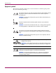
Troubleshooting and Diagnostics List of suspect FRUs If a hard failure or a recovered failure occurs, a list of possible FRUs that may have been at fault is returned. PROBLEM Internal Self-tests Most likely FRU A FRU B Least likely FRU C Figure 1: Suspect FRUs How suspect FRUs are evaluated Similar to treating symptoms rather than the real problem, the suspect FRUs given by the FRU isolation procedure may actually mask the root cause of the problem.
Troubleshooting and Diagnostics Running an internal test READY > ADMIN* >TEST* This section describes self-diagnostic tests that are available on the jukebox. Caution: Diagnostic tests should be run only by an authorized service representative. Descriptions of the self-diagnostic tests are included in this manual for information purposes only. If not properly completed, some of the internal diagnostic tests can corrupt your file system.
Troubleshooting and Diagnostics Table 4: Internal tests (Continued) Test Name Description DRIVE IO Makes a combination of moves with a PASS/FAIL result. It moves an optical disk from a randomly-chosen full slot to a randomly-chosen drive with a random flip. It then moves the cartridge back to its original slot with its original orientation. This test displays FAIL if there are no disks in the jukebox or if all storage slots are full. The drives and mailslot must be empty.
Troubleshooting and Diagnostics Table 4: Internal tests (Continued) Test Name Description EXERCISE MECH Runs the VERTICAL TEST, TRANSLATE TEST, FLIP TEST, MAGAZINE IO, DRIVE IO, and MAILSLOT IO tests. Each test runs one time per test loop. WELLNESS TEST Checks the general capability of the jukebox. Requires one loaded disk. The drives, transport, and mailslot must be empty. Runs INIT MECHANICS and EXERCISE MECHANICS. Each test runs one time per test loop.
Troubleshooting and Diagnostics Recovery procedures for specific hardware errors When a hardware failure occurs, a message displays on the control panel. If the failure occurs during the power-on sequence, DEVICE FAILED displays. If the failure occurs when loading a disk you may see LOAD ERROR or FULL. If a failure occurs while you are running a test, TEST FAILED displays. When you press ENTER, the jukebox displays information about the hardware failure from the error log.
Troubleshooting and Diagnostics Table 5: Hardware errors verification/recovery (Continued) Error Code (hex) 10h Invalid drive configuration Verification/Recovery Procedures For 1000ux/1900ux/2300ux models: ■ ■ ■ A 32-slot UDO jukebox must have two UDO drives in positions 1 and 2. A 64-slot UDO jukebox must have UDO drives in all four drive positions. A 64-slot mixed media jukebox must have UDO drives in positions 1 and 2, and MO drives in positions 3 and 4.
Troubleshooting and Diagnostics Table 5: Hardware errors verification/recovery (Continued) Error Code (hex) 26 Verification/Recovery Procedures 1F Vertical motor error Occurs when trying to sense a move of the carriage assembly. 1. If the translate assembly moves -- and you get a failure -- that means that it is not reading the encoder strip. Make sure the encoder strip is inside sensor. 2. If the translate assembly doesn’t move -- it probably is the motor leads, motor, or 24-volt power supply. a.
Troubleshooting and Diagnostics Table 5: Hardware errors verification/recovery (Continued) Error Code (hex) Verification/Recovery Procedures 3C Move to Vertical motion failed in the middle of a move or exchange 1. Look at the micro-move error of the failure in the error log (under INFO *, and Hardware Error in the control panel display). Also check the Source and Destination entries in the error log to verify what move was in process. 2. Make sure the encoder strip is inside sensor 3.
Troubleshooting and Diagnostics Table 5: Hardware errors verification/recovery (Continued) Error Code (hex) Verification/Recovery Procedures 43 Get cartridge from a drive Failed extracting a cartridge from a drive. 1. Look at the micro-move error of the failure in the error log (under INFO * and Hardware Error in the control panel display). 2. Remove rear panel and run the Wellness Test, Drive I/O test, and Exercise Mechanics test. Note where the problem occurs. If indicates the drive, change the drive.
Troubleshooting and Diagnostics Table 5: Hardware errors verification/recovery (Continued) Error Code (hex) Verification/Recovery Procedures 4D Find translate home Cannot translate the picker and/or sense that it has moved. 1. Run FIND XLAT HOME test from the control panel. 2. If the picker does not move at all, check the connections on the umbilical cable. If the connections are good and the picker still does not move, change the umbilical cable. 3.
Troubleshooting and Diagnostics Table 5: Hardware errors verification/recovery (Continued) Error Code (hex) Verification/Recovery Procedures 5E Powerfail clear path 1. Check that all paths are clear. 2. Test the vertical path sensor operation. 5F Powerfail restore cartridges A cartridge was physically moved after powerfail and before powerfail recovery. Check that no cartridges have been moved. 60 Repeater controller 1. Check cables between the controller PCA and the SCSI repeater PCA. 2.
Troubleshooting and Diagnostics Micro-move error codes Table 6: Micro-move error codes Micro-Move Error Code (hex) Description 01 Vertical over voltage exceeded limit set by firmware 02 Vertical over force exceeded limit set by firmware 03 Vertical servo error 04 Vertical time-out 05 Vertical open path 06 Vertical closed path 0A Plunge over voltage exceeded limit set by firmware 0B Plunge over force exceeded limit set by firmware 0C Plunge servo error 0D Plunge servo error 0E Plunge
Troubleshooting and Diagnostics Table 6: Micro-move error codes (Continued) Micro-Move Error Code (hex) 32 Description 36 Magazine measure failed 37 Test magazine failed 38 Return magazine failed 39 Clear magazine path 3C Mailslot put in saturate failed 3D Mailslot get out saturate failed 3E Mailslot put in accept failed 3F Mailslot get out accept failed 40 Measurement of mailslot depth failed 41 Recovery did not clear vertical path 42 Rotate mailslot in failed 43 Rotate mailslot
Troubleshooting and Diagnostics Table 6: Micro-move error codes (Continued) Micro-Move Error Code (hex) Description 6E Test failed 6F Media type test failed 70 Picker full 1000ux/1900ux/2300ux and 3800ux/7100ux Optical Jukebox Service Manual 33
Troubleshooting and Diagnostics Description of the robotic micro-moves Table 7: Micro-move IDs and expanded descriptions Micro-Move ID (hex) 34 Description 1 Move picker transport up. Fast. 2 Move picker transport down. Fast. 3 Move picker transport up slowly, checking for resistance. Used in the vertical find home sequence. 4 Move picker transport down slowly, checking for resistance. Used in the vertical find home sequence. 5 Move a small amount upward to relieve tension in the servos.
Troubleshooting and Diagnostics Table 7: Micro-move IDs and expanded descriptions (Continued) Micro-Move ID (hex) Description 6C First time plunge into magazine (first “get”). Feels for resistance to learn the distance to the cartridge when it is seated. 6D Retraction to pull the cartridge out of the magazine. 6F First part of a two-step move to put a cartridge into a magazine. Puts the cartridge nearly all the way in. Next part of move is micro-move 70.
Troubleshooting and Diagnostics Table 7: Micro-move IDs and expanded descriptions (Continued) Micro-Move ID (hex) 36 Description 8A Short plunge to test for a cartridge in a drive when the picker contains a cartridge. If resistance is felt, this is interpreted as a cartridge in the drive. Used in an ISTAT. 8B Plunge out. Used in error recovery. Is an attempt to push a cartridge out of the vertical picker path and into a magazine. 8C Retract thumbs back into the picker. Used in error recovery.
Troubleshooting and Diagnostics Table 7: Micro-move IDs and expanded descriptions (Continued) Micro-Move ID (hex) Description AB Move picker plunge assembly forward a small amount to complete the rearm of the picker mechanism. One of three moves used to make the top picker the active picker during a picker recalibration. AC Move picker plunge assembly forward to normal position after a active picker has been change by micro-moves AA and AB.
Troubleshooting and Diagnostics Table 7: Micro-move IDs and expanded descriptions (Continued) Micro-Move ID (hex) 38 Description BC Retract picker plunge assembly after detecting a cartridge in the drive. Used in an ISTAT when there is a cartridge in the picker. BD Retract picker plunge assembly to a point just short of where the thumbs would be released from their splayed position. Used if thumbs are splayed after checking magazines in an ISTAT.
Troubleshooting and Diagnostics Table 7: Micro-move IDs and expanded descriptions (Continued) Micro-Move ID (hex) Description D1 Short plunge during a mailslot “put.” Ducks under the mailslot rotation mechanism and positions the picker so it can move up all the way to mailslot insertion position. D2 Short plunge to put the cartridge all the way into the mailslot. D3 Short plunge during a mailslot “get”.
Troubleshooting and Diagnostics Table 7: Micro-move IDs and expanded descriptions (Continued) Micro-Move ID (hex) E0 Description For 1000ux/1900ux/2300ux models: Plunge rotate mailslot 5 (not used). For 3800ux/7100ux models: Mailslot starting a move out. E1 For 1000ux/1900ux/2300ux models: First of two moves rotating the mailslot in. Quickly retract the picker plunge assembly, pulling the mailslot most of the way in. Followed by micro-move E3.
Troubleshooting and Diagnostics Table 7: Micro-move IDs and expanded descriptions (Continued) Micro-Move ID (hex) Description E8 On powerup, testing for motion in the plunge motor. Opposite direction than in micro-move E7. E9 Plunge out to clear the picker vertical path. Used when path is blocked during powerup. EA Picker plunge assembly retraction to clear the picker vertical path. Used when path is blocked during powerup.
Troubleshooting and Diagnostics Using HP StorageWorks Library and Tape Tools HP StorageWorks Library and Tape Tools (L&TT) is a robust diagnostic tool for tape mechanisms, tape automation, magneto-optical and UDO products. L&TT provides functionality for firmware downloads, verification of device operation, maintenance procedures, failure analysis, corrective service actions and some utility functions.
Service Preparation 2 This chapter provides information on the following: ■ Protecting Yourself and the Product, page 44 ■ Electrostatic Discharge (ESD) Precautions, page 44 ■ Required Tools, page 44 ■ Service Access, page 45 ■ Identifying FRUs, page 47 1000ux/1900ux/2300ux and 3800ux/7100ux Optical Jukebox Service Manual 43
Service Preparation Protecting Yourself and the Product WARNING: Do not disassemble the optical drive mechanism. The optical drive mechanism becomes a Class 3B laser device when disassembled. If the drive is disassembled, exposure to the invisible laser beam and hazardous invisible laser radiation could result in blindness. Note: An optical drive that has been disassembled will not be accepted as an exchange assembly.
Service Preparation Service Access Caution: Do not switch off power to the jukebox until you are sure the SCSI bus is inactive. Switching off the jukebox when the SCSI bus is active can cause data loss and/or indeterminate bus states. WARNING: To prevent possible electric shock, disconnect the power cord before taking the jukebox apart. Caution: When servicing the jukebox, be sure that disk cartridges are not moved from their original slot locations.
Service Preparation Access for 3800ux/7100ux Models Figure 4: Access panel locations (for models 3800ux/7100ux) 46 1000ux/1900ux/2300ux and 3800ux/7100ux Optical Jukebox Service Manual
Service Preparation Identifying FRUs Note: The “x” in the part numbers listed in the following parts tables represents a number from “0” to “9” depending on the revision of the part. For example, if the part is newly released, the number will be “0”. The first time the part is revised, the number increments to “1”; the second time the part is revised, the number increments to“2”, and so on.
Service Preparation Figure 6: Exploded view for 1000ux/1900ux/2300ux models (2 of 3) 48 1000ux/1900ux/2300ux and 3800ux/7100ux Optical Jukebox Service Manual
Service Preparation Figure 7: Exploded view for 1000ux/1900ux/2300ux models (3 of 3) 1000ux/1900ux/2300ux and 3800ux/7100ux Optical Jukebox Service Manual 49
Service Preparation Figure 8: Power cabling for 1000ux/1900ux/2300ux models 50 1000ux/1900ux/2300ux and 3800ux/7100ux Optical Jukebox Service Manual
Service Preparation Figure 9: Rope and pulley system for 1000ux/1900ux/2300ux models 1000ux/1900ux/2300ux and 3800ux/7100ux Optical Jukebox Service Manual 51
Service Preparation Identifying FRUs for 3800ux/7100ux Models Figure 10 through Figure 15 show exploded views of the FRUs for models 3800ux/7100ux. Cross-reference Table 8 on page 57 for descriptions and part numbers for each FRU.
Service Preparation Figure 11: Exploded view for 3800ux/7100ux models (2 of 6) 1000ux/1900ux/2300ux and 3800ux/7100ux Optical Jukebox Service Manual 53
Service Preparation Figure 12: Exploded view for 3800ux/7100ux models (4 of 6) 54 1000ux/1900ux/2300ux and 3800ux/7100ux Optical Jukebox Service Manual
Service Preparation Figure 13: Exploded view for 3800ux/7100ux models (5 of 6) Figure 14: Exploded view for 3800ux/7100ux models (6 of 6) 1000ux/1900ux/2300ux and 3800ux/7100ux Optical Jukebox Service Manual 55
Service Preparation Figure 15: Ropes and pulley system for 3800ux/7100ux models 56 1000ux/1900ux/2300ux and 3800ux/7100ux Optical Jukebox Service Manual
Service Preparation FRU Part Numbers for All Models Note: FRU part numbers listed in Table 8 are common between all models unless otherwise noted. Note: For the latest information on FRU part numbers, visit http://partpage.corp.hp.com. Note: Some part numbers include an “x” which represents a number from “0” to “9”, depending on the revision of the part. For example, if the part is newly released, the number will be 0”.
Service Preparation Table 8: FRU Assemblies (Continued) FRU No.
Service Preparation Table 8: FRU Assemblies (Continued) FRU No.
Service Preparation Table 8: FRU Assemblies (Continued) FRU No.
FRU Removal and Replacement 3 This chapter provides information on the following: ■ FRU Removal and Replacement for 1000ux/1900ux/2300ux Models, page 62 ■ FRU Removal and Replacement for 3800ux/7100ux Models, page 94 1000ux/1900ux/2300ux and 3800ux/7100ux Optical Jukebox Service Manual 61
FRU Removal and Replacement FRU Removal and Replacement for 1000ux/1900ux/2300ux Models The following procedures describe removal and replacement procedures for 3800ux/7100ux jukebox FRUs.
FRU Removal and Replacement Replacing a Power Supply 1. Remove the right access panel (refer to “Access for 1000ux/1900ux/2300ux Models” on page 45). 2. Remove the power plug from the bottom of the power supply (see #1 on Figure 16). 3. Disconnect the cables from the top of the supply (see Figure 16). The 5V/12V supply has four cables (#2); the 24V supply has one cable (#3). 4. Remove the two T-20 screws at the top of the supply (see arrows on top of power supplies in Figure 16). 5.
FRU Removal and Replacement Replacing the Mailslot Assembly 1. Remove the front panel (refer to“Access for 1000ux/1900ux/2300ux Models” on page 45). 2. Remove the two T-15 mailslot mounting screws from the upper left side of the chassis (see arrows on the left side of Figure 17). These screws are recessed. Use a Torx driver with an extended shaft. 3. Unplug the mailslot cable from the interposer PCA. 4. Slide the mailslot out of the jukebox.
FRU Removal and Replacement Replacing the Control Panel Assembly 1. Remove the front panel (see “Access for 1000ux/1900ux/2300ux Models” on page 45). 2. Turn the panel upside down. 3. Remove the four T-10 sheet metal screws from the control PCA retaining ring to detach the control panel PCA from the mounting assembly (see the arrows on Figure 18). 4. Remove the control panel.
FRU Removal and Replacement Replacing an Optical Drive — Jukebox Offline Note: Before replacing a drive, obtain the most current version of the jukebox controller and drive firmware for the model and option of the jukebox you are servicing. Note: Online drive repair is not supported for 1000ux/1900ux/2300ux models. 1. Remove the back panel (see “Access for 1000ux/1900ux/2300ux Models” on page 45). 2. Remove the drive cables for the failed drive from the interposer PCA.
FRU Removal and Replacement 5. Remove the T-10 screws that hold the small cable access panel on the top of the drive enclosure. Remove the panel (see Figure 20). Figure 20: Unmounting a Drive From An Enclosure 6. Disconnect the drive cables from the rear of the drive. — drive interface cable — SCSI cable — drive power cable 7. Remove the four T-10 screws that hold the drive in the drive enclosure and slide the drive out of the enclosure.
FRU Removal and Replacement 8. If there is a disk in the drive, use a disk eject tool to remove the disk from the drive. a. Insert a small screwdriver or paper clip into the disk eject access hole (see Figure 21). b. When you feel firm pressure on the tip, push forward. The disk mechanism will eject the disk. Note: Remember whether the “A” or “B” side faces up when you remove the disk. The disk must be inserted into the replacement drive with the same orientation. Figure 21: Disk Eject Hole 9.
FRU Removal and Replacement Replacing a Media Detect Station 1. Remove the left access panel (the panel below the mailslot). See “Access for 1000ux/1900ux/2300ux Models” on page 45. 2. Remove all drive cables for the drive enclosure that contains the media detect station. Note: Take note of cable connections for easier reattachment. 3. Remove the drive enclosure from the chassis. 4. Remove the four T-10 screws holding the top and bottom access plates on the drive enclosure (see #1 and #2 in Figure 20).
FRU Removal and Replacement 8. Reattach the four T-10 screws that hold the drive in the drive enclosure, and reattach the cables removed in step 4. 9. Reattach the four T-10 screws holding the top and bottom access plates on the drive enclosure. 10. Reinstall the drive enclosure into the chassis. 11. Reattach the drive cables removed in step 2. 12. Reattach the back panel removed in step 1.
FRU Removal and Replacement Replacing the Interposer PCA 1. Remove the front access panel (see “Access for 1000ux/1900ux/2300ux Models” on page 45). 2. Disconnect all cables to the interposer PCA (see Figure 23). 3. Remove the eight T-20 screws holding the PCA to the chassis. Note: CHECK TO SEE IF THERE IS A CONFIGURATION MODULE MOUNTED ON THE PCA. IF A CONFIGURATION MODULE IS INSTALLED, TRANSFER THE MODULE TO THE REPLACEMENT PCA.
FRU Removal and Replacement Replacing the Picker 1. Remove the left access panel (refer to “Access for 1000ux/1900ux/2300ux Models” on page 45). 2. Pull the tab on the end of the picker umbilical cable to disconnect the cable from the bottom of the picker (see Figure 24).
FRU Removal and Replacement 3. Release the translate cable from the side of the translate frame nearest the front of the jukebox (see Figure 25): a. Depress the tension spring (#1) on the side of the translate frame to release the tension on the cable and allow you to pass the cable up through the slotted hole (#2). b. Slide the cable into the pinch slot on the side of the picker (#3). Placing the cable in the pinch slot prevents the cable from unraveling from the central picker hub.
FRU Removal and Replacement Caution: Raise the translate frame only by pulling on the vertical drive rope (see top arrow in Figure 26). The frame can be twisted by pulling it by the sides. A twisted frame may cause various errors in operation. 5. Raise the translate frame and picker up to a convenient working height so that you can access the underside of the picker. Insert a screwdriver into the vertical motor gear box to hold the frame in position. (see Figure 26).
FRU Removal and Replacement 6. Remove the T-10 sheet metal screw that holds the capture spring down (see Figure 27). Figure 27: Releasing the Picker Capture Bracket 7. Remove the capture spring by pulling it up and out of the unit. 8. Rotate the capture bracket 90 degrees and pull the bracket down and out (see Figure 28). Figure 28: Removing the Translate Frame Capture Bracket 9.
FRU Removal and Replacement 10. Tilt up the rear end of the picker and left it out of the frame (see Figure 29).
FRU Removal and Replacement Removing/Replacing the Translate Frame (Including the Picker) 1. Remove the right access panel (refer to “Access for 1000ux/1900ux/2300ux Models” on page 45). Caution: Raise the translate frame only by pulling on the vertical drive rope (see the top arrow on Figure 30). The frame can be twisted by pulling it by the sides. A twisted frame may cause various errors in operation. 2.
FRU Removal and Replacement Figure 31: Releasing the Lower End of the Vertical Encoder Strip 3. Unhook the encoder strip and hang it out of the way (see Figure 31). Pull down on the bottom of the encoder strip to release the strip from its retaining peg. Once released, the strip will slide up and out of the plastic guide. WARNING: The edges of the vertical encoder are sharp. Be careful. Caution: Handle the encoder strip with care and ONLY BY THE SOLID SIDE.
FRU Removal and Replacement 4. Remove the “visual locator” bracket on the (front) side of the picker translate frame (see Figure 32). Remove the two T-20 screws holding the bracket and rotate the bracket off. Figure 32: The Visual Locator Bracket 5. Disconnect the umbilical cable on the underside of the translate frame (see Figure 33).
FRU Removal and Replacement 6. Remove the tool you inserted into vertical motor gear box and move the translate frame down to the bottom of the jukebox. 7. Remove the three rope tensioners from the frame (#1, #2, and #3 on Figure 34). a. Remove two T-25 long screws per tensioner. Start with the tensioner at the rear end of the frame (#1 on Figure 34). b. Pull all three rope tensioners free of the translate frame. c. Pull the rear tensioner upwards to raise all three tensionsers up and out of your way.
FRU Removal and Replacement 8. Rotate the rear of the translate frame up and then remove the frame out to the side (see Figure 35). Figure 35: Rotating the Translate Frame Out of the Chassis Reassembly Notes Note: Take care to install the translate frame properly. If the frame is not mounted level, errors will be caused that will prevent the library from operating. The following steps explain proper mounting of the frame. 1. Place the frame back in the chassis. Let it rest on its support points.
FRU Removal and Replacement Figure 36: Remounting the Tensioners on the Translate Frame Mounting the Vertical Encoder Strip Move the translate frame up and lock it while reinstalling the encoder strip. Ensure that the encoder strip passes through the sensor slot on the sensor PCA mounted on the side of the picker frame. The strip may be moved off its mounting peg while you are replacing the translate frame in the chassis.
FRU Removal and Replacement Removing/Replacing the Vertical Encoder Strip 1. Remove the right access panel (refer to “Access for 1000ux/1900ux/2300ux Models” on page 45). WARNING: The edges of the vertical encoder are sharp. Be careful. Caution: Handle the encoder strip with care and ONLY BY THE SOLID SIDE. The CLEAR side is made up of very fine slits and CAN BE EASILY DAMAGED. 2. Release the lower end of the vertical encoder strip (see #1 on Figure 37). 3.
FRU Removal and Replacement Replacing the Vertical Motion Motor 1. Remove the left access panel (refer to “Access for 1000ux/1900ux/2300ux Models” on page 45). 2. Disconnect the two power cables to the vertical motor (see Figure 38). Note: Remember the orientation of the motor before removing it in the next step. The motor must be replaced in the same position on reassembly. 3. Remove two T-15 motor mounting screws on the gear box. Remove the motor (see Figure 38).
FRU Removal and Replacement Replacing the Vertical Motor Gear Box 1. Remove the right access panel (refer to “Access for 1000ux/1900ux/2300ux Models” on page 45). 2. Remove the translate frame (refer to “Removing/Replacing the Translate Frame (Including the Picker)” on page 77). 3. Pull the rear tensioner upwards to raise all three tensioners up to a convenient working height. Figure 39: Opening the Tensioners to Relieve Cable Tension 4.
FRU Removal and Replacement Figure 40: Disconnecting the Rope Coupler 8. Remove the drive rope from the coupler (see #2 on Figure 40) 9. Remove the drive motor and gear box (see Figure 41). a. Remove the T-25 screw from the base of the gear box. b. Tip the gear box forward and lift it out.
FRU Removal and Replacement Reassembly Notes When replacing the rear rope tensioner, be sure that the tensioner spring area is positioned so that it faces you. This ensures that the rope tensioner is in the right position to fasten to the translate frame (see Figure 42). To give yourself enough slack in the, fasten the drive rope ends to the rope tensioner before hanging the drive rope over the top two pulleys.
FRU Removal and Replacement Replacing the Controller PCA 1. Remove the right access panel (refer to “Access for 1000ux/1900ux/2300ux Models” on page 45). 2. Remove the six T-20 screws on the controller PCA cover (see Figure 44). Note the two reference pin holes on the rear edge of the cover. Use these pins to position the cover correctly during reassembly.
FRU Removal and Replacement Figure 45: Controller PCA Cables and Screws 3. Disconnect the following cables from the controller PCA (see Figure 45): — SCSI cable (#1) — Power cable (#2) — Motor encoder and power cables (#3) — Picker cable (#4) 4. Remove the seven T-20 screws from the controller PCA and remove the PCA.
FRU Removal and Replacement Replacing the Buffer Assembly 1. Remove the back access panel (refer to “Access for 1000ux/1900ux/2300ux Models” on page 45). 2. Remove the four T-20 screws holding the buffer module to the chassis. 3 2 4 1 1 2 Buffer board Buffer board module 3 4 Power cable to buffer board Screws Figure 46: Removing and replacing the buffer assembly 3. Disconnect the cables to the buffer assembly (see Figure 46). 4. Remove the four T-15 screws and remove the buffer assembly. 5.
FRU Removal and Replacement Replacing the SCSI Cable 1. Remove the right and rear access panels (refer to “Access for 1000ux/1900ux/2300ux Models” on page 45). 2. Remove the SCSI cable from the interface PCA. Do step 2 and step 3 of “Replacing the Buffer Assembly” on page 90. Remove only the SCSI cable on the bottom of the interface PCA. 3. Remove the SCSI cable from the controller PCA. Do step 2 through step 4 of “Replacing the Controller PCA” on page 88 to remove the controller PCA.
FRU Removal and Replacement Checking the RFI Adjustments Note: The following RFI adjustments must be maintained after servicing the jukebox. Depending on the service performed, these configurations may be altered. The purpose of this section is to remind you of the RFI adjustments that must remain in place. Be sure that there is an RFI clamp holding the SCSI and GPIO cable together as shown in Figure 47. (Clamp (#1) has end clips (#2) to hold the two plates together.
FRU Removal and Replacement Figure 48: Cable Clamps on the GPIO and SCSI Cables Figure 49: EMI Strip on the Right-Side Panel 1000ux/1900ux/2300ux and 3800ux/7100ux Optical Jukebox Service Manual 93
FRU Removal and Replacement FRU Removal and Replacement for 3800ux/7100ux Models The following procedures describe removal and replacement procedures for 1000ux/1900ux/2300ux jukebox FRUs.
FRU Removal and Replacement Replacing an Optical Drive — Jukebox Offline Note: Before replacing a drive, obtain the most current version of the jukebox controller and drive firmware for the model and option of the jukebox you are servicing. Note: Online drive repair is not supported for 3800ux/7100ux models. 1. Remove the three right-side panels and the upper and lower RFI panels (see Figure 50). 2. Remove all drive cables for the drive enclosure that contains the failed drive (see Figure 50).
FRU Removal and Replacement 6. Remove the drive cables from the rear of the failed drive (see Figure 52. — #1 - drive power cables — #2 - SCSI cable — #3 - drive interface cables 7. Slide the failed drive out of the enclosure.
FRU Removal and Replacement 8. If there is a disk in the drive, use a disk eject tool to remove the disk from the drive. a. Insert the eject tool (or paper clip) into the disk eject access hole (see Figure 53). b. When you feel firm pressure on the tip, push forward. The disk mechanism will eject the disk. Note: Remember whether the “A” or “B” side faces up when you remove the disk. The disk must be inserted into the replacement drive with the same orientation. Figure 53: Disk Eject Hole 9.
FRU Removal and Replacement Replacing a Media Detect Station 1. Remove the two lower right-side panels and the lower RFI panel (see Figure 4). 2. The media detect station is located in drive position 11/12 (the lowest drive position). Remove the fan cable from the media detect station. Note: Note the orientation of the media detect station before removing it from the drive enclosure. It occupies drive position 11, though the drive enclosure occupies both 11 and 12. 3.
FRU Removal and Replacement Replacing a Power Supply 1. Remove the three right-side panels and the upper and lower RFI panels (see “Access for 3800ux/7100ux Models” on page 46). 2. Remove the cables from the power supply that you are replacing (see Figure 54). — The top and bottom arrows identify the 5/12 V power supplies — The middle arrow identifies the 24 V power supply 3. Remove the power supply.
FRU Removal and Replacement Replacing the Mailslot Assembly 1. Remove the three right-side panels and the upper and lower RFI panels (see “Access for 3800ux/7100ux Models” on page 46). 2. Ensure that the mailslot sensor cable is disconnected from the upper interposer PCA (see Figure 55). 3. Remove the two T-20 mailslot mounting screws from the bottom of the mailslot (#2 on Figure 55). 4. Slide the mailslot out of the jukebox (see #3 on Figure 55).
FRU Removal and Replacement Replacing the Control Panel Assembly 1. Remove the three left-side panels (see “Access for 3800ux/7100ux Models” on page 46). 2. Disconnect the control panel cable from the control panel (#1 arrow Figure 56). 3. Remove the eight T-15 screws that mount the control panel to the front window. Remove the control panel (see Figure 56).
FRU Removal and Replacement Replacing an Interposer PCA (Upper and/or Lower) Note: IF YOU ARE REPLACING AN UPPER INTERPOSER PCA, CHECK TO SEE IF THERE IS A CONFIGURATION MODULE MOUNTED ON THE PCA. IF A CONFIGURATION MODULE IS INSTALLED, TRANSFER THE MODULE TO THE REPLACEMENT PCA. 1. Remove the lower and middle right-side access panels (see “Access for 3800ux/7100ux Models” on page 46). 2. Disconnect all cables to the interposer PCA(s) (see Figure 57 through Figure 59).
FRU Removal and Replacement 1 5 6 2 4 7 3 4 5 6 7 50-pin GPIO cable 50-pin GPIO cable connected to controller board 50-pin GPIO cable connected to upper interposer 50-pin GPIO cable connected to lower interposer 1000ux/1900ux/2300ux and 3800ux/7100ux Optical Jukebox Service Manual 103 1 2 3 Controller board Upper interposer board Lower interposer board Figure 57: GPIO cable connections
FRU Removal and Replacement 3 2 4 9 5 - 6 1 1 7 8 1 2 3 4 5 Interposer board (upper) 50-pin library SCSI cable Upper path clear sensor cable 50-pin GPIO cable Mailslot cable 6 7 8 9 Front panel cable Lower path clear sensor cable LVD SCSI cable Configuration module - Power cables Figure 58: Cable connections for upper interposer PCA 104 1000ux/1900ux/2300ux and 3800ux/7100ux Optical Jukebox Service Manual
FRU Removal and Replacement 6 5 4 3 1 2 1 2 3 Buffer board module Cable access slot LVD SCSI cables 4 5 6 Cable clamps Black self-adhesive strip Lower interposer board Figure 59: LVD SCSI cable connections 3. Remove the eight T-20 screws holding the interposer to the chassis (see Figure 60). 1 2 3 3 4 1 2 Upper interposer board LVD SCSI cable for upper interposer board 3 4 PEMs standoffs for lower interposer board Black self-adhesive strip Figure 60: Removing the interposer PCA 4.
FRU Removal and Replacement Caution: When reattaching cables to the interposer PCA(s), ensure that the cables labeled “Bus 1” attach to the upper interposer, and cables labeled “Bus 2” attach to the lower interposer. Also, it is essential to make sure the cables are oriented properly to avoid damage to them. 5. To install the replacement interposer PCA, follow steps 1 through 4 in reverse order.
FRU Removal and Replacement Replacing the Picker 1. Remove the lower and middle right-side access panels (see “Access for 3800ux/7100ux Models” on page 46). Extra panels are removed in Figure 61 for parts visibility in this description. 2. Pull the tab on the end of the picker umbilical cable to disconnect the cable from the bottom of the picker (see the arrow on Figure 61).
FRU Removal and Replacement 3. Release the translate cable from the side of the translate frame nearest the front of the jukebox (see Figure 62): a. Depress the tension spring (#1) on the side of the translate frame to release the tension on the cable and allow you to pass the cable up through the slotted hole (#2). b. Slide the cable into the pinch slot on the side of the picker (#3). Placing the cable in the pinch slot prevents the cable from unraveling from the central picker hub.
FRU Removal and Replacement 5. Raise the translate frame and picker up to a convenient working height so that you can access the underside of the picker (see #1 on Figure 63). Pull the frame up to the desired position, and insert a screwdriver into the hole at the rear of the vertical motor gear box to prevent the frame from descending (#2). Figure 63: Holding the Translate Frame in Position 6. Remove the T-10 sheet metal screw that holds the capture spring down (see Figure 64).
FRU Removal and Replacement 7. Remove the capture spring by pulling it up and out of the unit. 8. Rotate the capture bracket 90 degrees and pull the bracket down and out (see Figure 65). Figure 65: Removing the Translate Frame Capture Bracket 9. Remove the tool you inserted into the rear of the vertical motor gear box and lower the translate frame and picker to the bottom of the jukebox. 10. Tilt up the rear end of the picker and slide it out toward the back (see Figure 66).
FRU Removal and Replacement Removing/Replacing the Translate Frame (Including the Picker) 1. Remove the three left-side access panels (see “Access for 3800ux/7100ux Models” on page 46). 2. Remove the lower and middle right-side access panels. Caution: Raise the translate frame only by pulling on the vertical drive rope. The frame can be twisted by pulling it by the sides. A twisted frame may cause various errors in operation. 3.
FRU Removal and Replacement Figure 68: Releasing the Lower End of the Vertical Encoder Strip 4. Unhook the encoder strip and hang it out of the way (see Figure 68). Pull down on the bottom of the encoder strip to release the strip from its retaining peg. Once released, the strip will slide up and out of the plastic guide. WARNING: The edges of the vertical encoder are sharp. Be careful. Caution: Handle the encoder strip with care and ONLY BY THE SOLID SIDE (see Figure 68).
FRU Removal and Replacement 5. Remove the “visual locator” bracket on the (front) side of the picker translate frame (see Figure 69). Remove the T-20 screw holding the bracket and rotate the bracket off.
FRU Removal and Replacement 6. Disconnect the umbilical cable on the underside of the translate frame (see Figure 70. Figure 70: Disconnecting the Vertical Umbilical Cable From the Translate Frame 7. Remove the tool you inserted into vertical motor gear box and move the translate frame down to the bottom of the jukebox.
FRU Removal and Replacement 8. Remove the three rope tensioners from the frame (#1, #2, and #3 on Figure 71). a. Remove two T-25 long screws per tensioner. Start with the tensioner at the rear end of the frame (#1 on Figure 71). b. Pull all three rope tensioners free of the translate frame. c. Pull the rear tensioner upwards to raise all three tensionsers up and out of your way.
FRU Removal and Replacement 9. Rotate the rear of the translate frame up and then remove the frame out to the side (see Figure 72). Figure 72: Rotating the Translate Frame Out of the Chassis Reassembly Notes Note: Take care to install the translate frame properly. If the frame is not mounted level, errors will be caused that will prevent the library from operating. The following steps explain proper mounting of the frame. 1. Place the frame back in the chassis. Let it rest on its support points.
FRU Removal and Replacement Mounting the Vertical Encoder Strip Move the translate frame up and lock it while reinstalling the encoder strip. Ensure that the encoder strip passes through the sensor slot on the sensor PCA mounted on the side of the picker frame. The strip may be moved off its mounting peg while you are replacing the translate frame in the chassis.
FRU Removal and Replacement Removing/Replacing the Encoder Strip 1. Remove the three left-side and three rear access panels (see “Access for 3800ux/7100ux Models” on page 46). Caution: Raise the translate frame only by pulling on the vertical drive rope. The frame can be twisted by pulling it by the sides. A twisted frame may cause various errors in operation. 2.
FRU Removal and Replacement 3. Pull the lower end of the encoder strip down (#1 on Figure 73). The strip will come off its mounting peg. 4. Take the upper end of the encoder strip off the spring on the upper strip mount (see #2 on Figure 73). Reassembly Notes Carefully mount the encoder strip on the top spring. Route the strip to the lower encoder mount while making sure that the strip passes through the strip reader on the front corner of the translate frame.
FRU Removal and Replacement Replacing the Vertical Motion Motor 1. Remove the lower left-side access panel (see “Access for 3800ux/7100ux Models” on page 46). Extra panels are removed in Figure 74 for parts visibility in this description. 2. Disconnect the red and black power cables to the vertical motor (see Figure 74). Note: Note the orientation of the motor before removing it in the next step. The motor must be replaced in the same position on reassembly. 3.
FRU Removal and Replacement Replacing the Vertical Motor Gear Box 1. Remove the three left-side access panels (see “Access for 3800ux/7100ux Models” on page 46). 2. Follow the steps in “Removing/Replacing the Translate Frame (Including the Picker)” to remove the picker and translate frame. 3. Pull the rear tensioner upwards to raise all three tensioners up to a convenient working height (see #1 on Figure 75). Figure 75: Opening the Tensioners to Relieve Cable Tension 4.
FRU Removal and Replacement b. Pull both ends of the rope out of the tensioner. 6. Remove the drive cable from the top pulleys (#3 on Figure 76). 7. Remove the T-15 screw from the rope coupler cover (see #1 on Figure 76). Figure 76: Disconnecting the Rope Coupler 8. Remove the front and center ropes from the rope coupler (#2 and #3 on Figure 76). Note: The top and bottom ropes in the coupler are slave ropes. The center rope is the drive rope.
FRU Removal and Replacement 9. Remove the gear box by removing one T-25 screw from the base of the gear box. Tip the gear box forward and lift it out (see Figure 77).
FRU Removal and Replacement Reassembly Notes When remounting the rear rope tensioner on the drive rope, position the tensioner so that the spring is on the right side. The position of the tensioner is shown in the enlarged tensioner in Figure 78. It is recommended that you mount and secure the tensioners on the translate frame in the order shown on Figure 78.
FRU Removal and Replacement Replacing the Controller PCA 1. Remove the three right-side access panels and the lower and upper RFI panels (see “Access for 3800ux/7100ux Models” on page 46). 2. Remove all cables from the controller PCA (see Figure 79). — #1 - input power to the PCA — #2 - 24 V output — #3 - 24 V output to vertical motor — #4 - picker umbilical cable — #5 - GPIO — #6 - SCSI cable 3. Remove the seven T-20 screws holding the controller PCA to the chassis (see arrows on Figure 79). 4.
FRU Removal and Replacement Replacing the Power Distribution PCA 1. Remove the lower right-side access panel (see “Access for 3800ux/7100ux Models” on page 46). 2. Remove the power cable and other power distribution cables from the PCA. See Figure 80. — #1 - 24 V input to the controller PCA — #2 - 24 V from 24 V supply — #3 - input to the lower 5/12 V power supply — #4 - input to the upper 5/12 power supply — #5 - ground strap — # 6 - line input 3. Remove the power distribution PCA. a.
FRU Removal and Replacement Replacing a Buffer Assembly 1. Remove the lower right-side access panel (see “Access for 3800ux/7100ux Models” on page 46). 2. Remove the four T-20 screws that mount the assembly enclosure. Remove the enclosure. Figure 81: Unmounting the assembly enclosure 3. Remove all cables (power and SCSI) from the buffer assembly. 4. Remove the four T-15 screws that mount the buffer board to the inside of the module.
FRU Removal and Replacement 3 4 2 1 1 2 Buffer board Cable access slot 3 4 Buffer board module Power cable to buffer board Figure 82: Buffer board cabling 5. To install the replacement buffer assembly, repeat steps 1 through 4 in reverse order.
FRU Removal and Replacement Replacing the Vertical-Path-Clear PCA 1. Remove the lower rear access panel (see “Access for 3800ux/7100ux Models” on page 46). Extra panels are removed in Figure 83 for parts visibility in this description. 2. Remove the three T-20 screws that mount the PCA cover (#1 on Figure 83). 3. Remove the cable from the rear of the PCA (#2 on Figure 83). 4. Remove the six T-20 screws that mount the PCA to the chassis (#3 on Figure 83). Remove the PCA.
FRU Removal and Replacement Checking the RFI Adjustments Note: The following RFI adjustments must be maintained after servicing the jukebox. Depending on the service performed, these configurations may be altered. The purpose of this section is to remind you of the RFI adjustments that must remain in place. Refer to Figure 84 on the next page for the discussion below. Be sure that there is an RFI clamp holding the front panel cable to the chassis as shown by #1.
Index A listing of 21, 42 running 42 used by service 42 internal tests, running 21 access panel locations 46 authorized reseller, HP 9 C L checking RFI adjustments 130 conventions document 7 equipment symbols 8 text symbols 7 Library and Tape Tools 42 logs listing of 17 M D micro-move error codes 31 micro-move ID descriptions 34 diagnostic tests running 21 document conventions 7 related documentation 6 G getting help 9 H hardware error recovery 24 help, obtaining 9 host troubleshooting 13 HP au
Index optical drive 66, 95 picker 72, 107 power distribution PCA 126 power supply 99 SCSI cable 91 translate frame 77, 111 vertical motion gear box 85 vertical motion motor 84, 120 vertical motor gear box 121 vertical-path-clear PCA 129 required tools 44 RFI adjustments 92, 130 S SCSI bus type 13 symbols in text 7 symbols on equipment 8 132 T technical support, HP 9 tests internal 42 running 21 text symbols 7 tools required 44 troubleshooting 12, 13, 42 hardware errors 24 W warning symbols on equipment