HP StorageWorks SAN Switch rack mount kit installation instructions Sixth Edition (May 2007) *A7511-90902* Part Number: *A7511-90902*
© Copyright 2007 Hewlett-Packard Development Company, L.P. Hewlett-Packard Company makes no warranty of any kind with regard to this material, including, but not limited to, the implied warranties of merchantability and fitness for a particular purpose. Hewlett-Packard shall not be liable for errors contained herein or for incidental or consequential damages in connection with the furnishing, performance, or use of this material.
About this Document This document describes how to use the optional SAN Switch Rack Mount Kit to rack mount HP StorageWorks Storage Area Network (SAN) switches and routers.
Related Documentation For the latest documentation, please visit the following HP website: http://www.hp.com/go/san Before You Begin - Important Information about the Plenum The plenum is an air duct that attaches to the switch rails, enabling the switch to draw cooler air into the switch from outside the rack, rather than drawing in heated air from within the rack, see Figure 8.
Installation and Safety Guidelines Verify that the rack and the area around the rack meets the following requirements: ■ Plan a rack space that is 1.5 units high (2.6 inches; 6.7 cm), 19 inches (48.3 cm) wide, and at least 23 inches (68.6 cm) deep. For the MP Router or 4/64 SAN Switch, plan a rack space that is at least 2 units high. ■ Ground all equipment in the rack through a reliable branch circuit connection, and maintain ground at all times.
Using the SAN Switch Rack Mount Kit to Install an HP StorageWorks Device Read this section to install a SAN Switch or MP Router in an HP 9000 Series, HP 10000 Series, HP 10000 G2 Series or HP System/e rack. Note: The SAN Switch Rack Mount Kit installation requires one technician.
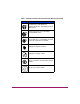
Table 1: Hardware included in the SAN Switch Rack Mount Kit (Continued) Item Description Fourteen (14) #8-32 x 3/16-inch Phillips pan-head screws with thread lock Fourteen (14) #8-32 x .
To install the HP StorageWorks device in a rack: Note: Figures and procedures throughout this document use “HP 10000 Series Rack” to reference both 10000 Series rack models (HP 10000 Series Rack and HP 10000 G2 Series Rack). 1. Check the contents of the SAN Switch Rack Mount Kit shipping carton to verify that all the required parts and hardware are available. See Table 1, Hardware included in the SAN Switch Rack Mount Kit. 2. Choose a mounting location in the rack. 3.
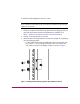
— For an HP System/e rack, install each of the two rear mounting brackets with two #10-32 x 1/2-inch Phillips pan-head screws and two #10 alignment washers as shown in Figure 2. Figure 2: Installing the Rear Mounting Brackets (HP System/e Rack) Note: Your SAN Switch Rack Mount Kit contains both left rails and right rails. The rails are labelled Right and Left.
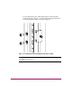
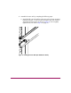
4. Assemble the outer rails by completing the following steps: a. Attach the left outer rail and the right outer rails to the rear mounting brackets using two 1/4-20 hex nuts with captive star lock washers. Attach the hex nuts loosely (as shown in Figure 3). Do not tighten; tighten the hex nuts later in step 3 on page 19.
b. Depending on the rack you are using, complete one of the following tasks: — For HP 10000 Series racks, install two #10-32 x 1/2-inch Phillips pan-head screws with captive star lock washers and two #10 adapter washers in the upper and lower hole locations of the right rail. Then install two #10-32 x 1/2-inch Phillips pan-head screws with captive star lock washers and two #10 adapter washers in the upper and lower hole locations of the left rail, as shown in Figure 4.
— For an HP System/e rack, install two #10-32 x 1/2-inch Phillips pan-head screws with captive star lock washers and two #10 alignment washers in the upper and lower hole locations of the right rail. Then install two #10-32 x 1/2-inch Phillips pan-head screws with captive star lock washers and two #10 alignment washers in the upper and lower hole locations of the left rail, as shown in Figure 5.
5. Depending on the device model, the SAN Switch Rack Mount Kit requires different screw types for securing the inner rails. Use Table 2 to determine the number and screw type for your specific switch or MP Router model. Caution: Do not use any other screws other than the ones provided in the kit. Use of longer screws may cause damage to internal components. Table 2: Number of Screws Required to Secure the Inner Rails Device Model #8-32 x .
c. To attach the inner rails to the SAN Switch 2/32 use the screw holes marked 32. d. To attach the inner rails to the MP Router, use the screw holes marked R. e. To attach the inner rails to the SAN Switch 4/32, 4/32B SAN Switch, 4/64 SAN Switch or the 400 MP Router use the screw holes marked 16. Caution: Remember to use the screw holes labelled 8 when attaching the inner rails to the SAN Switch 2/16V or SAN Switch 2/16N. 7.
OLE CONS MT1 MG MT2 MG Y IVIT ACT ED 15 SPE 14 13 12 11 LINK ED SPE GbE FC/ CT LINK/A 10 9 8 7 6 5 4 63 3 0 VAC 6.0 Hz A 47- -24 2 100 1 0 AC DC OK OK R POWE S PORT EM SYST 63 0 VAC 6.
Note: For factory integration only, tighten the #8-32 x 3/16-inch Phillips pan-head screw with thread lock and torque between 6 to 8 inch-pounds. 8. If installing one of the following switches, you must install the plenum that ships in the accessory kit with the rack mount hardware: ■ SAN Switch 2/8V ■ SAN Switch 2/16 ■ SAN Switch 2/16V ■ 4/8 SAN Switch ■ 4/16 SAN Switch ■ 4/32B SAN Switch See Installing the Plenum (if required), page 17 for complete installation instructions.
Installing the Plenum (if required) See Before You Begin - Important Information about the Plenum, page 4 to determine if you need to install the plenum before inserting the device in the rack. To install the plenum: 1. Place the device (with inner rails attached) on a flat surface, see Figure 8. 2. Obtain the plenum and four 8-32 x .312 Phillips Pan-head SEMs screws from the accessory kit. These are the same screws used to attach the inner rails in step 5 of the previous section. 3.
Securing the Device to the Outer Rails To secure the device to the outer rails: 1. Insert the switch with the attached inner rails into the outer rails. Note: This step applies to installing a switch in HP 9000 Series, HP 10000 Series or HP System/e racks. 2. Insert the device into the rack and install (2) #10-32 x 1/2-inch Phillips pan-head screws with captive star lock washers with one on each side. See Figure 9 and Figure 10.
Figure 10: Securing the Device (in an HP System/e rack) 3. Tighten the hex nuts installed in step 4 on page 10. See Figure 3. Note: To uninstall a device, remove the middle #10-32 x 1/2-inch Phillips pan head screw with captive star lock washer from either side of the rack uprights. This completes the rack mount procedure.