Web Tools Administrator’s Guide Supporting Fabric OS v5.2.
Copyright © 2006, Brocade Communications Systems, Incorporated. ALL RIGHTS RESERVED. Brocade, the Brocade B weave logo, Fabric OS, File Lifecycle Manager, MyView, Secure Fabric OS, SilkWorm, and StorageX are registered trademarks and Tapestry is a trademark of Brocade Communications Systems, Inc., in the United States and/or in other countries. FICON is a registered trademarks of IBM Corporation in the U.S. and other countries.
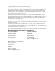
Document History The following table lists all versions of the Web Tools Administrator’s Guide. Document Title Publication Number Summary of Changes Publication Date Web Tools User’s Guide v2.0 53-0001536-01 N/A September 1999 Web Tools User’s Guide v2.2 53-0001558-02 N/A May 2000 Web Tools User’s Guide v2.3 53-0000067-02 N/A December 2000 Web Tools User’s Guide v3.0 53-0000130-03 N/A July 2001 Web Tools User’s Guide v2.
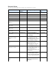
Document Title Publication Number Summary of Changes Publication Date Web Tools Administrator’s Guide 53-1000049-01 Updates to support new switch types (4900, 7500) and Fabric OS v5.1.0, including FCR, FCIP, and the FR4-18i port blade. Web Tools EZ information is moved to a separate book. January 2006 Web Tools Administrator’s Guide 53-1000049-02 Updates to the FCIP chapter to clarify how to configure tunnels. April 2006 Web Tools Administrator’s Guide 53-1000194-01 Updates for Fabric OS v5.2.
Contents About This Document How This Document Is Organized . . . . . . . . . . . . . . . . . . . . . . . . . . . . . . . . . xv Supported Hardware and Software . . . . . . . . . . . . . . . . . . . . . . . . . . . . . . . . . xvi What’s New in This Document. . . . . . . . . . . . . . . . . . . . . . . . . . . . . . . . . . . . xvii Document Conventions. . . . . . . . . . . . . . . . . . . . . . . . . . . . . . . . . . . . . . . . . . xviii Text Formatting. . . . . . . . . . . . . . . . . . . . . . .
Session Management . . . . . . . . . . . . . . . . . . . . . . . . . . . . . . . . . . . . . . . . . . . 1-13 Logging In. . . . . . . . . . . . . . . . . . . . . . . . . . . . . . . . . . . . . . . . . . . . . . . . . 1-13 Logging Out . . . . . . . . . . . . . . . . . . . . . . . . . . . . . . . . . . . . . . . . . . . . . . . 1-16 Chapter 2 Using the Web Tools Interface Viewing the Switch Explorer . . . . . . . . . . . . . . . . . . . . . . . . . . . . . . . . . . . . . 2-1 SilkWorm 24000 Director. . .
Chapter 3 Managing Fabrics and Switches Managing Fabrics and Switches Using Web Tools. . . . . . . . . . . . . . . . . . . . . 3-1 Launching the Switch Admin Module . . . . . . . . . . . . . . . . . . . . . . . . . . . 3-3 Refreshing the Switch Admin Module . . . . . . . . . . . . . . . . . . . . . . . . . . . 3-3 Launching the Telnet Window . . . . . . . . . . . . . . . . . . . . . . . . . . . . . . . . . . . . 3-3 Configuring IP and Netmask Information . . . . . . . . . . . . . . . . . . . . . .
Monitoring Events . . . . . . . . . . . . . . . . . . . . . . . . . . . . . . . . . . . . . . . . . . . . . 3-20 Displaying Fabric Events . . . . . . . . . . . . . . . . . . . . . . . . . . . . . . . . . . . . . 3-21 Displaying Switch Events . . . . . . . . . . . . . . . . . . . . . . . . . . . . . . . . . . . . . 3-22 Filtering Fabric and Switch Events. . . . . . . . . . . . . . . . . . . . . . . . . . . . . . 3-23 Displaying a Fabric Topology Report. . . . . . . . . . . . . . . . . . . . . . . . . . . . .
Chapter 7 Using the FCIP Tunneling Service About the FCIP Tunneling Service. . . . . . . . . . . . . . . . . . . . . . . . . . . . . . . . . 7-1 Compression . . . . . . . . . . . . . . . . . . . . . . . . . . . . . . . . . . . . . . . . . . . . . . . 7-3 Fastwrite . . . . . . . . . . . . . . . . . . . . . . . . . . . . . . . . . . . . . . . . . . . . . . . . . . 7-3 Tape Pipelining . . . . . . . . . . . . . . . . . . . . . . . . . . . . . . . . . . . . . . . . . . . . . 7-4 IKE/IPSec Policy . . . .
Managing Administrative Domains . . . . . . . . . . . . . . . . . . . . . . . . . . . . . . . . 8-11 Adding and Removing Members . . . . . . . . . . . . . . . . . . . . . . . . . . . . . . . 8-11 Renaming Admin Domains . . . . . . . . . . . . . . . . . . . . . . . . . . . . . . . . . . . 8-13 Deleting Admin Domains . . . . . . . . . . . . . . . . . . . . . . . . . . . . . . . . . . . . . 8-13 Chapter 9 Administering Zoning Introducing Zoning . . . . . . . . . . . . . . . . . . . . . . . . . . . . . . . .
Managing QuickLoops . . . . . . . . . . . . . . . . . . . . . . . . . . . . . . . . . . . . . . . . . . 9-14 Creating QuickLoops . . . . . . . . . . . . . . . . . . . . . . . . . . . . . . . . . . . . . . . . 9-14 Adding and Removing Members of a QuickLoop . . . . . . . . . . . . . . . . . . 9-15 Renaming QuickLoops . . . . . . . . . . . . . . . . . . . . . . . . . . . . . . . . . . . . . . . 9-16 Deleting QuickLoops . . . . . . . . . . . . . . . . . . . . . . . . . . . . . . . . . . . . . . . .
Chapter 10 Monitoring Performance Monitoring Performance Using Web Tools . . . . . . . . . . . . . . . . . . . . . . . . . . 10-1 Predefined Performance Graphs . . . . . . . . . . . . . . . . . . . . . . . . . . . . . . . . 10-2 User-Defined Graphs . . . . . . . . . . . . . . . . . . . . . . . . . . . . . . . . . . . . . . . . 10-6 Canvas Configurations . . . . . . . . . . . . . . . . . . . . . . . . . . . . . . . . . . . . . . . 10-6 Launching the Performance Monitor Module . . . . . . . . . . . . . . . .
Chapter 12 Working With Diagnostic Features Managing Trace Dumps . . . . . . . . . . . . . . . . . . . . . . . . . . . . . . . . . . . . . . . . . 12-1 How a Trace Dump Is Used . . . . . . . . . . . . . . . . . . . . . . . . . . . . . . . . . . . 12-2 Setting Up Automatic Trace Dump Transfers . . . . . . . . . . . . . . . . . . . . . 12-3 Disabling Automatic Trace Uploads. . . . . . . . . . . . . . . . . . . . . . . . . . . . . 12-3 Displaying Switch Information. . . . . . . . . . . . . . . . . . . . . . .
Chapter 14 Administering Extended Fabrics About Extended Link Buffer Allocation. . . . . . . . . . . . . . . . . . . . . . . . . . . . . 14-1 Configuring a Port for Long Distance . . . . . . . . . . . . . . . . . . . . . . . . . . . . . . 14-3 Chapter 15 Administering the iSCSI Target Gateway Supported Platforms for iSCSI . . . . . . . . . . . . . . . . . . . . . . . . . . . . . . . . . . . . 15-1 About the iSCSI Service . . . . . . . . . . . . . . . . . . . . . . . . . . . . . . . . . . . . . . . . .
Chapter 17 Configuring Standard Security Features Creating and Maintaining User-Defined Accounts. . . . . . . . . . . . . . . . . . . . . 17-1 Creating and Deleting User-Defined Accounts . . . . . . . . . . . . . . . . . . . . 17-4 Changing Account Parameters . . . . . . . . . . . . . . . . . . . . . . . . . . . . . . . . . 17-5 Maintaining Passwords . . . . . . . . . . . . . . . . . . . . . . . . . . . . . . . . . . . . . . . 17-7 Configuring Access Control List Policies . . . . . . . . . . . . . . . . .
Chapter 19 Limitations General Web Tools Limitations . . . . . . . . . . . . . . . . . . . . . . . . . . . . . . . . . . . 19-1 Platform-Specific Limitations. . . . . . . . . . . . . . . . . . . . . . . . . . . . . . . . . . . . . 19-6 Limitations of Using a Mozilla Browser . . . . . . . . . . . . . . . . . . . . . . . . . . . .
About This Document This document is an administrator’s guide written to help fabric administrators monitor and modify switches and fabrics from a Web-based user interface.
• Chapter 6, “Administering ISL Trunking”, provides information on managing the optionally licensed ISL Trunking feature. • Chapter 7, “Using the FCIP Tunneling Service”, provides information on managing the FCIP tunneling service and configuring an FCIP interswitch link. • Chapter 8, “Managing Administrative Domains”, provides information on managing Admin Domains.
In those instances in which procedures or parts of procedures documented here apply to some switches but not to others, this guide identifies exactly which switches are supported and which are not. Although many different software and hardware configurations are tested and supported by Brocade Communications Systems, Inc. for Fabric OS 5.2.
Document Conventions This section describes text formatting conventions and important notices formats.
Additional Information This section lists additional Brocade and industry-specific documentation that you might find helpful. Brocade Resources The following related documentation is provided on the Brocade Documentation CD-ROM and on the Brocade Web site, through Brocade Connect. Note Go to http://www.brocade.com and click Brocade Connect to register at no cost for a user ID and password.
SilkWorm 24000 • • SilkWorm 24000 Hardware Reference Manual SilkWorm 24000 QuickStart Guide SilkWorm 24000/48000 • • • • • • • • • Port Blade and Filler Panel Replacement Procedure Control Processor Blade Replacement Procedure Blower Assembly Replacement Procedure Cable Management Tray and Guide Replacement Procedure Chassis Door Replacement Procedure WWN Bezel and Card Replacement Procedure Power Supply and Filler Panel Replacement Procedure 14U Rack Mount Kit Installation Procedure Mid-Mount Rack Kit
SilkWorm 200E • SilkWorm 200E Hardware Reference Manual (for v5.
FICON® CUP Enables IBM host-based management programs to manage FICON fabric switches in-band by sending commands to the Fabric OS emulated control device. FCIP Tunneling The optional Fibre Channel over Internet protocol (FCIP) Tunneling Service enables Fibre Channel frames to “tunnel” through IP networks by dividing frames, encapsulating the result in IP packets on entering the tunnel, and then reconstructing them as they leave the tunnel.
2. Switch Serial Number The switch serial number and corresponding bar code are provided on the serial number label, as shown here: : *FT00X0054E9 FT00X0054E9 The serial number label is located as follows: 3.
xxiv Web Tools Administrator’s Guide Publication Number: 53-0000194-01
Chapter Introducing Web Tools 1 Brocade Web Tools is a graphical user interface (GUI) that enables administrators to monitor and manage single or small fabrics, switches, and ports from a standard workstation. It is an optionally licensed product that runs on Brocade Fabric OS. Web Tools provides the administrative control point for Brocade Advanced Fabric Services, including Advanced Zoning, ISL Trunking, Advanced Performance Monitoring, and Fabric Watch.
1 Requirements Web Tools requires any browser that conforms to HTML version 4.0, JavaScript version 1.0, and Java Plug-in 1.4.2_08 or higher. Brocade has certified and tested Web Tools on the platforms shown in Table 1-1. Table 1-1 Certified and Tested Platforms Operating System Browser Java Plug-In1 Solaris 10 Firefox 1.5.0.1 1.5.0_06 Linux Red Hat AS4 Firefox 1.5.0.1 1.5.0_06 Windows 2003 Server, SP1 Internet Explorer 6.0 1.5.0_06 Windows XP, SP2 Internet Explorer 6.0 1.5.0_06 1.
1 Configuring Internet Explorer Correct operation of Web Tools with Internet Explorer requires specifying the appropriate settings for browser refresh frequency and process model. Browser pages should be refreshed frequently to ensure the correct operation of Web Tools. To set the refresh frequency 1. Click Tools > Internet Options in the browser. 2. Click the General tab and click Settings (under “Temporary Internet Files”). 3.
1 To install the JRE on your Solaris or Linux client workstation 1. Locate the JRE on the Internet, at the following URL: http://java.sun.com/products/archive/j2se/5.0_06/index.html Note This URL points to a non-Brocade Web site and is subject to change without notice. 2. Select JRE 5.0 Update 6. 3. Follow the instructions to install the JRE. 4. Create a symbolic link from this location...: $FIREFOX/plugins/libjavaplugin_oji.so ...to this location: $JRE/plugin/$ARCH/ns600/libjavaplugin_oji.
1 Configuring the Java Plug-In If you are managing fabrics with more than 10 switches or 1000 ports, or if you are using the iSCSI Gateway module extensively, you should increase the default heap size to 256 MB to avoid out-ofmemory errors. Use the following procedure to increase the default heap size in the Java Control Panel. To configure the Java Plug-in on Windows 1. From the Start menu button, select Settings > Control Panel > Java. 2. Click the Java tab. Figure 1-2 3.
1 5. Type the following information: -Xms256m -Xmx256m -Xms256m sets the minimum heap size and -Xmx256m sets the maximum heap size. In this instance, the minimum and maximum sizes are 256 MB. 6. Click OK to close the Java Runtime Settings dialog box. 7. Click Apply to apply your settings and close the Java Control Panel. Installing a Web Tools License You can install a Web Tools license either through telnet or over the Web.
1 Installing a Web Tools License Through the Web Launching Web Tools from any nonlicensed switch automatically displays the license dialog box. If the fabric already contains at least one licensed switch, you can use Web Tools to view and license other switches from the licensed switch. If you do not have a switch that has a Web Tools license installed on it then Web Tools is active for only 30 days from the date that the switch is activated.
1 Web Tools is part of the Fabric OS of a switch. When you launch Web Tools on a switch, you can manage other switches in the fabric that have lower or higher firmware versions. It is important to note that when accessing these switches you are opening the remote switch’s version of Web Tools, and the functionality available for those switches might vary. Launching Web Tools You can launch Web Tools on any workstation with a compatible Web browser installed.
1 Figure 1-4 EZSwitchSetup Interface Figure 1-5 Web Tools Interface Web Tools Administrator’s Guide Publication Number: 53-0000194-01 1-9
1 Figure 1-6 Web Tools—AP Edition Interface Administrative Domains An “administrative domain” (Admin Domain or AD) is a logical grouping of fabric elements that defines what switches, ports, and devices you can view and modify. An Admin Domain is a filtered administrative view of the fabric. The logical view presented within an Admin Domain does not hide fabrics, chassis, switches, and slots; however, the attributes of switch ports and end devices are filtered based on Admin Domain membership.
1 AD0 is a special Admin Domain that contains all switches, ports, and devices that have not been put into other Admin Domains. AD255, another special domain, is an unfiltered view of the entire physical fabric. Note Some features work only in AD255 when user-defined domains are present, such as ACL management. By default, all fabric elements belong to AD0. In Fabric OS v5.2.
1 For example, if the switch WWN is: 10:00:00:60:69:e4:24:e0 then the converted WWN for that switch in AD1 is: 50:06:06:9e:42:4e:09:01 Admin Domains and Zoning Each Admin Domain has its own zone database, with both defined and effective zone configurations and all related zone objects (zones, zone aliases, and zone members). Within an Admin Domain, you can configure zoning only with the devices that are present in that Admin Domain. Before you implement Admin Domains, you must set the default zoning mode.
1 Session Management A “Web Tools session” is defined as the connection between the Web Tools client and its managed switch. A session is established when you log in to a switch through Web Tools. A single session is shared by the Switch Explorer and all child windows launched from it. Closing or navigating away from the Switch Explorer ends the session and invalidates all related child windows; closing the child windows, however, does not end the session.
1 To log in 1. Click Run on the signed certificate applet It is recommended that you check the box Always trust content from this publisher in order for some of the more simple functions to work, such as export and copy. You must accept the signed certificate from Brocade when you launch Web Tools. Figure 1-7 2. Signed Applet Certificate Click OK in the security banner window, if one appears. The login window displays. Figure 1-8 Login Dialog Box 3. Type your user name. 4. Type the password.
1 The Login dialog box displays the Admin Domain options. • • Click the Home Domain radio button to log in to your default Admin Domain. Click the User Specified Domain radio button to log in to another Admin Domain instead of your home domain. Type the Admin Domain name or number. Figure 1-9 5. Login Dialog Box with Admin Domain Options Click OK (or click Change Password and Login if you have changed your password).
1 Logging Out You can end a Web Tools session either by logging out or by closing the Switch Explorer browser window. All windows belonging to the session are invalidated. After a short delay, a message appears stating the session has been invalidated, but you must close them manually. Sometimes you might be logged out of a session involuntarily, without explicitly clicking the Logout button.
Chapter Using the Web Tools Interface 2 This chapter contains the following sections: • • • • • • “Viewing the Switch Explorer” on page 2-1 “Displaying Tool Tips” on page 2-12 “Refresh Rates” on page 2-13 “Displaying Switches in the Fabric” on page 2-14 “Using Web Tools and Secure Mode” on page 2-15 “Working with Web Tools: Recommendations” on page 2-16 Viewing the Switch Explorer The first thing you see when you log in to a switch with Web Tools is the Switch Explorer (see Figure 2-1 on page 2-3).
2 Some buttons in the Switch Explorer might be grayed out, which means either your account does not have sufficient privileges to access this feature, or your currently selected Admin Domain does not meet some condition to access the feature. • A single session is shared by the Switch Explorer and all child windows launched from it. (See “Session Management” on page 1-13 for more information on sessions.) • Access control is enforced across the entire session.
2 SilkWorm 24000 Director Figure 2-1 shows an example with pointers displaying the various parts of the Web Tools Switch Explorer for a SilkWorm 24000 director. In this figure, the SilkWorm 24000 director has two domains; however, only one domain is displayed. You can view and manage only one domain at a time, even though both domains are enclosed in the same chassis. To manage the other domain, you must log in to it separately.
2 SilkWorm 48000 Director Figure 2-2 shows an example with pointers displaying the various parts of the Web Tools Switch Explorer for a SilkWorm 48000 director.
2 SilkWorm 4100 Switch Figure 2-3 shows an example with pointers displaying the various parts of the Web Tools Switch Explorer for a SilkWorm 4100 switch. This is the same format as the Switch Explorer used in Web Tools for the SilkWorm 200E, 3250, 3850, 3900, 4900, and 7500 switches.
2 Blade View Figure 2-4 is a view of the Web Tools switch view of the blades you can install in a SilkWorm 48000 director.
2 Fabric Tree The Fabric Tree is the left panel of the Switch Explorer. The Fabric Tree displays all switches in the fabric, including switches that do not have a Web Tools license and switches that are not owned by your selected Admin Domain. The switches that are not owned by your currently selected Admin Domain are shown in the Fabric Tree with their switch status. Any switches segmented before Web Tools is launched are not displayed.
2 Admin Domain Context The Admin Domain field in the Switch Explorer displays the currently selected Admin Domain and allows you to change to a different one. All the Admin Domains assigned to you are available in the drop-down menu. For most administrative tasks you must be in either AD0 or the physical fabric. The following procedure describes how to change the Admin Domain. This action is referred to as “changing the Admin Domain context.” To change the Admin Domain context 1.
2 2. Click OK in the confirmation window. The Switch Explorer refreshes to display the new Admin Domain context. A progress bar displays while the Switch Explorer is refreshing. Figure 2-6 Admin Domain Change in Progress Any child windows that were opened in the previous Admin Domain context are disabled; you must close these windows manually. There might be a delay of up to 30 seconds before the child windows are disabled.
2 Switch View The Switch View displays a graphical representation of the selected switch, including a real-time view of switch and port status. Select a switch icon in the Fabric Tree to access the Switch View for that switch. Figure 2-7 shows the Switch View for a SilkWorm 4100 switch. Figure 2-7 SilkWorm 4100 Switch View The layout of information is different for the Switch View of different switch types. See Figure 2-1 through Figure 2-3 for examples of different Switch Views.
2 Switch View Button Menu The Switch View button menu is the launch point for the following: • • • • • • • • • Switch Events screen Telnet interface Fabric Watch module Switch Admin module Performance Monitor module High Availability (HA) Admin module FC Routing module Administrative Domain module iSCSI Management module Figure 2-8 Switch View Button Menu for a Director Class Switch Some of these functions require a license key to activate.
2 Switch Information View The Switch Information View displays vital switch information such as switch name, status, Fabric OS version, domain ID, IP address, WWN, and current zone configuration. The information in the Switch Information View is polled every 15 seconds. The Switch Information View is located beside the graphic representation of the switch for the SilkWorm 24000 and 48000 directors.
2 When you mouse over a port, you can view the port number, port index, port type (E, F, L, or U_Port), port status (online or offline), and port state (in-sync, no_sync, no light, or no module). If you rightclick the port, you can view the same information as the mouseover tool tip as well as the hexadecimal value of the port. For example, Figure 2-9 displays the mouseover tool tip for port 19 and the right-click tool tip for port 30.
2 Retrieval time increases when you are in a large fabric as there is more data to fetch from the switch(s). • • • Processor speed of the system you are using may slow down the refresh rate. OS-Job Scheduling if you are using a host-system in the data center impacts the refresh rate JVM-Performance can contribute to causing interval differences between what is on-screen and how long it is actually taking.
2 Using Web Tools and Secure Mode When secure mode is enabled on switches you manage through Web Tools, there are certain requirements and scenarios of which you should be aware. You should read through the requirements and scenarios in this section if you plan to use Web Tools to manage any switches that have secure mode enabled. Web Tools Access and HTTP_POLICY When secure mode is enabled, access to the Web Tools interface is controlled by HTTP_POLICY.
2 Disabled Functionality Telnet access to a switch and the Telnet button in Web Tools are both disabled when secure mode is enabled for a fabric. You must use sectelnet or SSH to access the Fabric OS CLI in a secure fabric. These capabilities are not accessible from Web Tools. For more information on sectelnet or SSH, see the Secure Fabric OS Administrator’s Guide. The SNMP Access Control List is replaced with RSNMP_POLICY and WSNMP_POLICY when secure mode is enabled for a fabric.
Chapter Managing Fabrics and Switches 3 This chapter contains the following sections: • • • • • • • • • • • • • • “Managing Fabrics and Switches Using Web Tools,” next “Launching the Telnet Window” on page 3-3 “Configuring IP and Netmask Information” on page 3-4 “Configuring a syslog IP Address” on page 3-5 “Enabling and Disabling Blades” on page 3-6 “Configuring a Switch” on page 3-7 “Rebooting the Switch” on page 3-8 “Changing System Configuration Parameters” on page 3-9 “Managing Licensed Features”
3 Figure 3-1 Switch Admin Module With the exception of switch time, information displayed in the Switch Admin module is not updated automatically by Web Tools. To update the information displayed in the Switch Admin module, see “Refreshing the Switch Admin Module” on page 3-3. Caution Any changes you make in the Switch Admin module are in a buffered environment and are not applied to the switch until you save the changes.
3 Launching the Switch Admin Module Most of the management procedures in this chapter are performed from the Switch Admin module. To access the Switch Admin module 1. Select a switch from the Fabric Tree. The selected switch appears in the Switch View. 2. Click the Admin button on the Switch View. The Switch Admin module displays (as shown in Figure 3-1 on page 3-2). Refreshing the Switch Admin Module You can refresh the fabric element information displayed at any time using the following procedure.
3 Configuring IP and Netmask Information When you configure IP and netmask information for the SilkWorm 24000 or 48000 director, it is on a logical-switch basis. This means that for each logical switch, you must configure IP and subnet mask information individually. When you change the Ethernet IP, subnet mask, gateway IP, or Fibre Channel IP and subnet mask from Web Tools, there is a normal loss of network connection to the switch.
3 5. Click Apply. 6. Exit and relaunch Web Tools to continue working. Configuring a syslog IP Address The syslog IP represents the IP address of the server that is running the syslog process. The syslog daemon reads and forwards system messages to the appropriate log files and/or users, depending on the system configuration. When one or more IP addresses are configured, the switch forwards all error log entries to the syslog on the specified servers. Up to six servers are supported.
3 Enabling and Disabling Blades The procedure in this section applies only to the SilkWorm 24000 and 48000 directors (bladed switches). To enable or disable a blade 1. Launch the Switch Admin module as described on page 3-3. 2. Click the Blade tab. The Enable Blade column in the Blade tab pane indicates whether the blade is enabled. Figure 3-3 3-6 Blade Tab 3. Check the Enable Blade checkbox for each blade you want to enable. Uncheck the checkbox to disable the blade.
3 Configuring a Switch Use the Switch tab of the Switch Admin module to perform basic switch configuration. Figure 3-1 on page 3-2 shows an example of the Switch tab. Enabling and Disabling a Switch You can identify if a switch is enabled or disabled in the Switch Admin module by looking at the lowerright corner: the icon means that the switch is enabled, and the icon means that the switch is disabled. To enable or disable a switch 1. Launch the Switch Admin module as described on page 3-3. 2.
3 Changing the Switch Domain ID Although domain IDs are assigned dynamically when a switch is enabled, you can request a specific ID to resolve a domain ID conflict when you merge fabrics. To change the switch domain ID 1. Launch the Switch Admin module as described on page 3-3. 2. Disable the switch, as described in “Enabling and Disabling a Switch” on page 3-7. 3. Click the Switch tab. 4. Type a new domain ID in the Domain ID field. The domain ID is an integer between 1 and 239. 5. Click Apply.
3 Performing a Fast Boot A fast boot reduces boot time significantly by bypassing power-on self test (POST). To perform a switch fast boot 1. Launch the Switch Admin module as described on page 3-3. 2. Click the Firmware Download tab (see Figure 4-2 on page 4-5). 3. Click the Fastboot radio button. 4. Click Apply. Performing a Reboot Use the following procedure to reboot the CP and execute the normal power-on booting sequence. To perform a switch reboot 1.
3 Configuring Fabric Parameters You can configure the following fabric parameters using the Configure tab and Fabric subtab of the Switch Admin module (as shown in Figure 3-4 on page 3-11): • BB Credit The buffer-to-buffer credit is the number of buffers available to attached devices for frame receipt. The default BB Credit is 16. The range is 1–27. • R_A_TOV Resource allocation timeout value (in milliseconds).
3 Figure 3-4 Configure Tab, Fabric Subtab To configure fabric parameters 1. Launch the Switch Admin module as described on page 3-3. 2. Disable the switch as described in “Enabling and Disabling a Switch” on page 3-7. 3. Click the Configure tab. 4. Click the Fabric subtab. 5. Make the fabric parameter configuration changes. 6. Click Apply. 7. Enable the switch as described in “Enabling and Disabling a Switch” on page 3-7.
3 Enabling Insistent Domain ID Mode When insistent domain ID (ID_ID) mode is enabled, the current domain setting for the switch is insistent; that is, the same ID is requested during switch reboots, power cycles, CP failovers, firmware downloads, and fabric reconfigurations. If the fabric does not assign the insistent domain ID, the switch segments from the fabric. To enable insistent domain ID mode 1. Launch the Switch Admin module as described on page 3-3. 2.
3 Configuring Arbitrated Loop Parameters You can configure the following arbitrated loop parameters using the Configure tab and Arbitrated Loop subtab of the Switch Admin module: Send Fan Frames Check this box to specify that fabric address notification (FAN) frames are sent to public loop devices to notify them of their node ID and address.
3 Managing Licensed Features Feature licenses might be supplied with switch software, or you can purchase licenses separately from your switch vendor, who will provide you with keys to unlock the features. License keys are provided on a per-chassis basis, so for products that support multiple logical switches (domains), a license key applies to all domains within the chassis.
3 Activating a License on a Switch Before you can unlock a licensed feature, you must obtain a license key. You can either use the license key provided in the paperpack document supplied with switch software or see the Fabric OS Administrator’s Guide for instructions on how to obtain a license key at the Brocade Web site (www.brocade.com). Note Some licenses (for example, Trunking) do not take effect until the switch is rebooted. To activate a license on a switch 1.
3 Administering High Availability High-Availability (HA) features provide maximum reliability and nondisruptive replacement of key hardware and software modules. The procedures in this section apply only to the SilkWorm 24000 and 48000 directors, because the High Availability module is available only on these switch types. See the Fabric OS Administrator’s Guide for additional information about High Availability.
3 2. Click the Hi Avail button on the Switch View. The HA Admin module displays. Figure 3-6 High Availability Module CP Tab Note that the background color of the HA Status at the top of the module is the same as the background color of the Hi Avail button. The HA Admin module contains two tabs: • The Service tab displays information about the switch. When the hardware is configured as a dual switch, the Service tab displays information about both switches.
3 Synchronizing Services on the CP A nondisruptive CP failover is only possible when all the services have been synchronized between both CPs. To synchronize the services 1. Launch the Hi Avail module as described in “Launching the High Availability Module” on page 3-16. 2. Verify that HA Summary field displays Non-Disruptive Failover Ready. If the HA Status field displays Non-Disruptive Failover Ready, you are done. If the HA Status field displays Disruptive Failover Ready, continue with step 3. 3.
3 Figure 3-7 HA Module Services Tab Initiating a CP Failover A nondisruptive failover might take about 30 seconds to complete. During the failover, all of the Web Tools windows and all associated child-windows are invalidated. You must close all Web Tools windows and relaunch Web Tools. To initiate a CP failover 1. Launch the Hi Avail module as described in “Launching the High Availability Module” on page 3-16. 2.
3 Monitoring Events Web Tools displays fabric-wide and switch-wide events. Event information includes sortable fields for the following: • • • • • • • • Switch name Message number Time stamp Indication of whether the event is from a logical switch or a chassis The number of successive events of the same kind Severity level Unique message identifier (in the form moduleID-messageType) Detailed error message for root cause analysis There are four message severity levels: Critical, Error, Warning, and Info.
3 Displaying Fabric Events Events are displayed for all switches in the fabric in the Fabric Events window (see Figure 3-8). Fabric events are not automatically polled. You must click Refresh from the Fabric Events window to poll fabric events. Switch events are automatically polled every 15 seconds. Fabric Events can be collected only for switches that have the same security level (http or https) as the launch switch.
3 Displaying Switch Events The Switch Events window displays a running log of events for the selected switch (see Figure 3-9 on page 3-22). Switch events are polled and updated every 15 seconds, so there is no refresh-on-demand option for switch events, as there is for the fabric events. For two-switch configurations, all chassis-related events are displayed in the event list of each logical switch for convenience. Figure 3-9 Switch Events Window To display switch events 1.
3 Filtering Fabric and Switch Events You can filter the events in the Fabric Events window and Switch Events window by time, severity, message ID, and service. You can apply either one type of filter at a time or multiple types of filters at the same time. The Switch and Fabric Events windows both have a Filter button. Click the Filter button to display the Event Filter dialog box (see Figure 3-10 on page 3-23).
3 6. Click OK. The filter is enabled and the enabled filter type is displayed in the events window. To filter events by event severity levels 1. Launch the Fabric or Switch Events window as described in “Displaying Fabric Events” on page 3-21 or “Displaying Switch Events” on page 3-22. 2. Click Filter. The Event Filter dialog box displays. 3. Click Level. 4. Click the event levels you want to display. 5. Click OK.
3 Displaying a Fabric Topology Report A fabric topology report lists all of the domains in the fabric and the active paths for each domain. A sample fabric topology report is shown in Figure 3-11 on page 3-25. To view a fabric topology report 1. Click the Fabric Topology icon on the Fabric Toolbar. The Fabric Topology window displays. 2. Click the Print button to print a topology report. A Print button is located at the top and bottom of the report. Both buttons have the same function.
3 Displaying the Name Server Entries Web Tools displays Name Server entries listed in the Simple Name Server database (see Figure 3-12 on page 3-26). This includes all Name Server entries for the fabric, not only those related to the local domain. Each row in the table represents a different device. Admin Domain considerations: The Name Server table is filtered based on Admin Domain membership of the fabric devices.
3 2. Optional: Check the Auto Refresh checkbox on the Name Server window. Type an auto-refresh interval (in seconds); the minimum (and default) interval is 15 seconds. The Name Server entries will refresh at the rate you set. To print the Name Server entries 1. Click the Name Server icon on the Fabric Toolbar. The Name Server Table displays. 2. Click Print. 3. The Page Setup dialog box displays. Make changes, as appropriate. 4. Click OK in the Page Setup dialog box. The Print dialog box displays.
3 Physically Locating a Switch Using Beaconing Use the Beacon button to physically locate a switch in a fabric. The beaconing function helps to physically locate a switch by sending a signal to the specified switch, resulting in an LED light pattern that cycles through all ports for each switch (from left to right).
Chapter Maintaining Configurations and Firmware 4 This chapter contains the following information: • • “Maintaining Configurations,” next “Performing a Firmware Download” on page 4-4 Maintaining Configurations It is important to maintain consistent configuration settings on all switches in the same fabric, because inconsistent parameters (such as inconsistent PID formats) can cause fabric segmentation.
4 Figure 4-1 Configure Tab, Upload/Download Subtab Backing Up a Configuration File Keep a backup copy of the configuration file in case the configuration is lost or unintentional changes are made. You should keep individual backup files for all switches in the fabric. You should avoid copying configurations from one switch to another. When you back up a configuration file for a SilkWorm 24000 configured with two logical switches, it is on a logical-switch basis.
4 • If the current Admin Domain owns the switch and you are logged in with any role that allows config upload/download, the following will be saved in the configuration file: • Local zone configuration iSCSI config (if any) All other config information except Admin Domain configuration information If you invoke it from AD255 and you are logged in with any role that allows config upload/ download), the following will be saved in the configuration file: - Configuration information for zones in all Admin
4 4. Click the Upload/Download subtab (see Figure 4-1 on page 4-2). 5. Click the Config Download to Switch radio button. 6. Type the host IP, user name, file name, and password. 7. Type the configuration file with a fully qualified path. 8. Select a protocol to use to transfer the file. 9. Click Apply. You can monitor the progress by looking at the Upload/Download progress bar on the Configure tab. 10. Enable the switch, as described in “Enabling and Disabling a Switch” on page 3-7.
4 To download a new version of the firmware 1. Launch the Switch Admin module as described on page 3-3. 2. Click the Firmware Download tab. Figure 4-2 Firmware Download Tab 3. Click the Firmware Download radio button. 4. Type the host IP address, user name, password, and fully qualified path to the file release.plist. The path name should follow the structure below: ////release.
4 4-6 Web Tools Administrator’s Guide Publication Number: 53-0000194-01
Chapter Managing Your Ports 5 This chapter describes how to manage FC and gigabit Ethernet (GbE) ports. See “Viewing and Configuring EX_Ports” on page 11-6 for information on how to view and configure EX_Ports. This chapter contains the following sections: • • • • • • • • “Viewing and Managing Ports Using Web Tools” on page 5-1 “Configuring Ports” on page 5-5 “Follow the steps outlined in the wizard.
5 To launch the Port Management module 1. Click an accessible port in the Switch View to launch the Port Management module in a separate window. Click tabs to display either FC ports or GbE ports Figure 5-1 Task Bar displays list of tasks you can perform on the selected port. Port Management Module, Port Detail View The Port Management module displays information about the ports on the switch.
5 Port Management Module Components The Port Management module (shown in Figure 5-1) has the following components: • • Two tabs on the top: FC Ports and GigE Ports. If the switch does not have GbE ports, the GigE Ports tab is not shown. - To display all of the FC ports on the switch (physical FC ports and logical FCIP ports), click the FC Ports tab. - To display all of the GbE ports, click the GigE Ports tab. (On the FR4-18i blade, each GbE port can have up to eight logical FCIP ports.
5 Figure 5-2 Port Management Module, Table View Identifying Controllable Ports All ports have a “Controllable” attribute, which represents a combination of the RBAC and Admin Domain permissions. Figure 5-1 and Figure 5-2 show the Controllable attribute. The Controllable attribute is No in the following situations: • If your account has read-only permission, all accessible ports display in read-only mode, regardless of the Admin Domain context. All configuration functionality is disabled.
5 Configuring Ports Web Tools provides wizards to assist you in configuring ports. This section describes how you can configure FC ports, logical FCIP ports, GbE ports, and NPIV ports. Configuring FC Ports With the FC Port Configuration wizard, you can configure allowed port types, port speed, and long distance mode for physical ports. The following procedure describes how to launch the FC Port Configuration wizard. The wizard is selfexplanatory, so the explicit steps are not documented here.
5 Allowed Port Types For FC ports, the Port Management module displays the following values relating to port type: Port Type This is the actual or current port type. If the port is offline, this value is the allowed types (or U_Port, if no type constraint has been specified). If the port is online, this value is the type the port has actually negotiated to. Allowed Port TypeThe allowed or configured port type.
5 To configure FCIP ports 1. Click a port in the Switch View to launch the Port Management module (see Figure 5-1 on page 5-2). 2. Click the FC Ports tab. 3. Select the logical port you want to configure in the tree on the left side of the window. 4. Click the General subtab. 5. Click Edit Configuration in the task bar. The FC Port Configuration wizard launches. The wizard fields are populated with the current configuration values. Figure 5-4 6.
5 The following procedure describes how to launch the GigE Port Configuration wizard. The wizard is self-explanatory, so the explicit steps are not documented here. To configure GbE ports 1. Click a port in the Switch View to launch the Port Management module (see Figure 5-1 on page 5-2). 2. Click the GigE Ports tab. 3. Select the port you want to configure in the tree on the left side of the window. 4. Click the General subtab. 5. Click Edit Configuration in the task bar.
5 To rename a port 1. Click a port in the Switch View to launch the Port Management module (see Figure 5-1 on page 5-2). 2. Click the FC Ports tab. 3. Click the switch or slot that contains the port you want to rename in the tree on the left side of the window. 4. Select the port in the table on the right side of the window. 5. Click Rename in the task bar. 6. Type a name for the port and click Ok. To delete the existing port name, type spaces or leave a blank string and click Ok.
5 5. Click Enable or Disable in the task bar. If a task is grayed out, that means that the port is already in that state. For example, if Enable is grayed out, the port or ports are already enabled. On multiple selections, when both enabled and disabled ports are selected, both Enabled and Disabled buttons are active. When you click either Enable or Disable, it will be applicable to all the ports selected. 6. Click Yes in the confirmation window.
5 Enabling and Disabling NPIV Ports N-Port ID Virtualization (NPIV) enables a single Fibre Channel protocol port to appear as multiple, distinct ports, providing separate port identification within the fabric for each operating system image behind the port (as if each operating system image has its own unique physical port). NPIV assigns a different virtual port ID to each Fibre Channel protocol device. NPIV enables you to allocate virtual addresses without impacting your existing hardware implementation.
5 Activating Ports The SilkWorm 200E can be purchased with 8, 12, or 16 licensed ports. The SilkWorm 4100 can be purchased with 16, 24, or 32 licensed ports. The SilkWorm 4900 can be purchased with 32, 48, or 64 licensed ports. As your needs increase, you can activate unlicensed ports by purchasing and installing the Brocade Ports on Demand optional licensed product. Ports on Demand is ready to be unlocked in the switch firmware.
5 Swapping Port Index If a port malfunctions, or if you want to connect to different devices without having to re-wire your infrastructure, you can move traffic from one port to another (swap ports) without changing the I/O Configuration Data Set (IOCDS) on the mainframe computer. When you perform a port swap, Web Tools automatically disables the two ports, swaps the area IDs, and enables the ports. To swap ports 1.
5 Port Index attribute indicates whether the port has been swapped.
Chapter Administering ISL Trunking 6 This chapter contains the following information: • • • “About Interswitch Link Trunking” on page 6-1 “Displaying Trunk Group Information” on page 6-2 “Disabling or Reenabling Trunking Mode on a Port” on page 6-3 About Interswitch Link Trunking Interswitch link (ISL) trunking optimizes network performance by forming trunking groups that can distribute traffic across a shared bandwidth. A trunking license is required on each switch that participates in the trunk.
6 Figure 6-1 Trunking Tab Displaying Trunk Group Information Use this procedure to display the following information about ISL Trunking groups: • • • Trunk group number identifier Master port Member ports To view information on a trunk group 6-2 1. Launch the Switch Admin module as described on page 3-3. 2. Click the Trunking tab. 3. Optional: Click Refresh to refresh the information.
6 Disabling or Reenabling Trunking Mode on a Port When the trunking license is activated, trunks are automatically established on eligible ISLs and trunking capability is enabled by default on all ports. Use the following procedure to disable trunking on a port or to reenable trunking if it has been disabled. Trunking is not supported on logical ports, GbE ports, or EX_Ports. Admin Domain considerations: You can enable and disable trunking for a port only when the current Admin Domain owns the switch.
6 6-4 Web Tools Administrator’s Guide Publication Number: 53-0000194-01
Chapter Using the FCIP Tunneling Service 7 This chapter describes the Fibre Channel over IP (FCIP) Tunneling Service. It contains the following sections: • • • “About the FCIP Tunneling Service” on page 7-1 “Configuring an FCIP Interswitch/Interfabric Link” on page 7-7 “Managing the FCIP Tunneling Service” on page 7-11 About the FCIP Tunneling Service The FCIP Tunneling Service is an optional feature that enables you to use Fibre Channel “tunnels” to connect SANs over IP-based networks.
7 Fibre Channel frame encapsulation occurs on the sending port and the reconstruction of Fibre Channel frames occurs on the receiving port. This encapsulation and reconstruction is transparent to the initiator and target. This chapter uses the terms “local” and “remote” this way: the local switch is the switch that initiates the FCIP connection request, and the remote switch is the switch that listens for FCIP connection requests. Figure 7-1 illustrates a portion of a Fibre Channel network using FCIP.
7 Compression The compression feature is a per-tunnel feature that allows the Fibre Channel data frames to be compressed before they sent over the tunnel as FCIP frames. The compression can be enabled or disabled using the portCfg command. The configuration of this feature is optional and by default the feature is disabled. The Fibre Channel command frames and all the frames that are generated from or destined for the control processor are not compressed even when compression is enabled on a tunnel.
7 Tape Pipelining Tape pipelining reduces the number of round trip times required to complete a SCSI write I/O and also eliminates the sequential nature of SCSI I/O. This results in reducing the I/O completion latency and increasing FCIP ISL bandwidth utilization. FCIP tape pipelining reduces the wait time for backup applications while performing backup to tape devices and eliminates the sequential nature of I/O.
7 IPSec helps provide in-depth defense against: • Network-based attacks from untrusted computers, which can result in the denial-of-service of applications, services, or the network • • • • Data corruption Data theft User-credential theft Administrative control of servers, other computers, and the network Limitations Consider the following limitations if you plan to use IPSec: • Policies cannot be altered.
7 Table 7-2 explains the fields and related choices to create an IKE/IPSec policy. Table 7-2 7-6 IKE/IPSec Configuration Choices Field Description Choices Policy Type You can create either an IKE policy or an IPSec policy IKE IPSec Policy Number This parameter helps you keep track of the number of policies you have created on your switch. You can choose any number from 1 through 32. You can define up to 32 IKE and 32 IPSec policies per switch.
7 Configuring an FCIP Interswitch/Interfabric Link Following are the steps for configuring an FCIP interswitch/interfabric link (ISL/IFL): 1. (Optional) “Configuring an IKE or IPSEC Policy” on page 7-7 If you are planning to use IPSec, you must configure the policies first. 2. “Configuring Virtual Ports” on page 7-8. 3. “Configuring Interfaces, Routes, and Tunnels” on page 7-9. Web Tools provides a wizard to do the following: 4. a. Define the IP interfaces of the GbE port. b.
7 4. Select a policy type from the drop down menu. Figure 7-2 Create an IKE/IPSec Policy 5. Choose a policy number. 6. Select an Encryption Algorithm. 7. Select an Authentication Algorithm. 8. (IKE only) Select a Perfect Forward Secrecy. 9. (IKE only) Select a Diffie-Hellman Group. 10. Enter a value for the Security Association Lifetime in number of seconds. Configuring Virtual Ports Each GbE port support up to eight virtual ports.
7 Configuring Interfaces, Routes, and Tunnels Web Tools provides a wizard to assist you in configuring an FCIP interswitch/interfabric link (ISL/IFL). With the GigE Port Configuration wizard, you can add IP interfaces, add IP routes, and configure FCIP tunnels. The following procedure describes how to launch the GigE Port Configuration wizard. The wizard is self-explanatory, so the explicit steps are not documented here.
7 Figure 7-3 GigE Port Configuration Wizard: Selecting Tunnels To configure the FCIP interfaces, routes, and tunnels 1. Click a port in the Switch View to launch the Port Admin module in a separate window (see Figure 5-1 on page 5-2). 2. Click the GigE Ports tab. 3. Select the port you want to configure in the tree on the left side of the window. 4. Click the General subtab. 5. Click Edit Configuration in the task bar. The GigE Port Configuration wizard launches.
7 Enabling Persistently Disabled Ports Ports on the SilkWorm 7500 and FR4-18i are, by default, persistently disabled. Before you can successfully configure FCIP interswitch links, you must enable the ports. Caution VEX_Port Users: If the fabric is already connected, leave the ports disabled until after you have configured the VEX_Port; this will prevent unintentional merging of the two fabrics.
7 Managing IP Interfaces for a GbE Port You can configure a new IP interface, edit an existing IP interface, or delete an IP interface by clicking the Add, Edit, and Delete tasks respectively on the IP Interfaces tab for a GbE port. Before you can delete an IP interface, you must first delete the corresponding FCIP tunnel. To add a new IP interface 1. Click a port in the Switch View to launch the Port Management module in a separate window (see Figure 5-1 on page 5-2). 2. Click the GigE Ports subtab.
7 To edit an IP interface 1. Click a port in the Switch View to launch the Port Management module in a separate window (see Figure 5-1 on page 5-2). 2. Click the GigE Ports subtab. 3. Click the port you want to edit and click the IP Interfaces subtab. 4. Select the IP interface to edit in the table on the right side of the window. 5. Click Edit in the task bar. The Edit IP Interface dialog box displays, populated with the current configuration values. 6.
7 Managing IP Routes for a GbE Port You can configure a new IP route, edit an existing user-defined IP route, or delete an IP route by clicking the Add, Edit, and Delete tasks respectively on the IP Routes tab for a GbE port. Note For each IP interface created in the GbE port, one default IP route will be automatically created. To add a new IP route 1. Click a port in the Switch View to launch the Port Management module in a separate window (see Figure 5-1 on page 5-2). 2. Click the GigE Ports subtab.
7 To edit an IP route 1. Click a port in the Switch View to launch the Port Management module in a separate window (see Figure 5-1 on page 5-2). 2. Click the GigE Ports subtab. 3. Click the port you want to edit and click the IP Routes subtab. 4. Select the IP route to edit in the table on the right side of the window. 5. Click Edit in the task bar. The Edit IP Route dialog box displays, populated with the current configuration values. Retype the metric for the IP Route. 6. Click OK.
7 Caution Both ends of the tunnel must be identically configured. Compression, fastwrite, tape pipelining, or IKE/ IPSec needs to be either enabled or disabled at both ends of the tunnel. In the case of a mismatch, the tunnel will not be established. See “Configuring Interfaces, Routes, and Tunnels” on page 7-9 for additional information on configuring the tunnels. To add a new FCIP tunnel 1.
7 To edit FCIP tunnel configuration 1. Click a port in the Switch View to launch the Port Management module in a separate window (see Figure 5-1 on page 5-2). 2. Click the GigE Ports tab. 3. Click on the port you want to edit. 4. Click the FCIP Tunnels subtab. 5. Select the tunnel to edit in the table on the right side of the window. 6. Click Edit Configuration in the task bar. The GigE Port Configuration wizard launches. The wizard fields are populated with the current configuration values. 7.
7 7-18 Web Tools Administrator’s Guide Publication Number: 53-0000194-01
Chapter Managing Administrative Domains 8 This chapter contains the following information: • • • • • “About Administrative Domains” on page 8-1 “Implementing Administrative Domains” on page 8-3 “Using the Admin Domain Module” on page 8-4 “Creating and Populating Domains” on page 8-8 “Managing Administrative Domains” on page 8-11 About Administrative Domains Using administrative domains (Admin Domains or ADs), you can partition the fabric into logical groups and allocate administration of these groups
8 User-Defined Admin Domains AD1 through AD254 are user-defined Admin Domains. These user-defined Admin Domains can be created only by a physical fabric administrator in AD255. System-Defined Admin Domains AD0 and AD255 are special Admin Domains and are present in every AD-capable fabric.
8 AD255 or Physical Fabric AD255 is a virtual domain that contains all devices, switches, and switch ports in the fabric. AD255 presents an unfiltered view of the fabric and is also referred to as the physical fabric. The term “physical fabric” is used in Web Tools only. You can use AD255 to: • • • • Manage other Admin Domains. Get an unfiltered view of the fabric. Manage ACL and distribution (can be managed in AD0 if no other Admin Domains are present).
8 Using the Admin Domain Module You can view and manage Admin Domains through the Admin Domain module, shown in Figure 8-1. You access the Admin Domain module by clicking the AD button in the Switch View. Figure 8-1 Admin Domain Module, Summary View The Admin Domain module displays information about the Admin Domains defined in the fabric. If you launch the Admin Domain module from AD255 (physical fabric), then the module displays the current content of all Admin Domains.
8 Figure 8-2 Admin Domain Module, Detail View The Admin Domain module has Export, Copy, Print, and Search links at the top of the tables. These options are not available if the table does not have any content. You must accept the Brocade Certificate at the beginning of the login to Web Tools to enable the functionality of Export and Copy. • • • • Click Export to save the contents of the table to a tab-delimited file. Click Copy to copy the contents of the table in tab-delimited text format to a file.
8 Figure 8-3 Searching for a Text String in a Table Launching the Admin Domain Module This section describes how to launch the Admin Domain module, from which the Admin Domain configuration procedures are performed. If you want to configure Admin Domains, you must launch the Admin Domain module from the physical fabric context. If you are in any Admin Domain other than the physical fabric, the module launches in read-only mode. To launch the Admin Domain module 1.
8 Refreshing Admin Domain Information Any changes you make to the Admin Domain module are saved to a local buffer; they are not applied to persistent storage until you invoke one of the transactional operations listed in the Actions menu. You can refresh the Admin Domain information at any time to reflect changes that might have been made by other users or to back out of current, unsaved work and start again.
8 Closing the Admin Domain Module It is very important to remember that any changes you make in the Admin Domain module are not saved automatically. To close the Admin Domain module 1. From the Admin Domain module, click File > Close. Any changes in the buffer that have not been saved, a warning dialog box displays, asking you to confirm that you want to close the Admin Domain session without saving the changes. 2.
8 To create a domain 1. Launch the Admin Domain module as described on page 8-6. 2. Click New in the toolbar. The Create Admin Domain wizard launches. Figure 8-4 3. 4. Create Admin Domain Wizard Assign a name using either the Auto Assigned or User Specified radio button. Assign an Admin Domain ID using either the Auto Assigned or User Specified radio button. Yo Note You cannot auto-assign both the Admin Domain Name and Admin Domain ID.
8 Figure 8-5 8. Adding Members to an Admin Domain Click Next. The wizard displays a summary of the Admin Domain. Read the summary to verify the Admin Domain setup is correct. Figure 8-6 9. Summary View Click Finish to close the wizard. 10. Repeat step 2 through step 9 to create additional Admin Domains.
8 11. Click Save to save the new Admin Domain configuration to persistent storage. 12. Click Apply to enforce the new Admin Domain configuration as the effective configuration. To activate or deactivate an Admin Domain 1. Launch the Admin Domain module as described on page 8-6. 2. In the left pane, select the Admin Domain you want to activate or deactivate. 3. Click Activate to activate the Admin Domain. Click Deactivate to deactivate the Admin Domain. 4.
8 3. Click Modify. The Modify Admin Domain wizard launches. Figure 8-7 4. Modify Admin Domain Wizard Assign members to the Admin Domain by selecting them in the Available Members section and clicking Add, Add Ports, or Add Devices. • Select a switch, port, or device in the Available Members tree and click Add to add the selected element. Alternatively, you can press the Insert key to add your selections.
8 Renaming Admin Domains You can change the name of an Admin Domain, including an auto-assigned ID name. To rename a domain 1. Launch the Admin Domain module as described on page 8-6. 2. Select the Admin Domain in the right side pane. 3. Click Rename. 4. Enter the new name. 5. Click OK. 6. Click Save in the Admin Domain module to save the new Admin Domain configuration to persistent storage. 7. Click Apply to enforce the new Admin Domain configuration as the effective configuration.
8 Deleting All User-Defined Admin Domains When you clear the Admin Domain configuration, all user-defined Admin Domains are deleted and all fabric resources (switches, ports, and devices) are returned to AD0. You cannot clear the Admin Domain configuration if zone configurations exist in any of the userdefined Admin Domains. To clear the entire Admin Domain configuration 1. Launch the Admin Domain module as described on page 8-6. 2. Click Clear.
Chapter Administering Zoning 9 This chapter briefly describes zoning and provides the procedures for managing zoning using Brocade Web Tools.
9 Zoning and Admin Domains Each Admin Domain has its own zone database, with both defined and effective zone configurations and all related zone objects (zones, zone aliases, and zone members). Within an Admin Domain, you can configure zoning only with the devices that are present in that Admin Domain (direct members). If you upgrade a fabric to Fabric OS 5.2.0 or higher, the zone database from the pre-v5.2.0 fabric is referred to as the “root zone database” and is owned by AD0.
9 Launching the Zone Admin Module This section describes how to launch the Zone Admin module, from which all zoning procedures are performed. You cannot open the Zone Admin module from AD255 (physical fabric). To launch the Zone Administration module 1. Select a switch from the Fabric Tree. If you select a switch that is different from the launch switch, you will be prompted for a user name and password to log in to the switch for Fabric OS versions 5.2.0 or higher.
9 Managing Zoning with WebTools You can monitor and manage zoning through the Web Tools Zone Admin module. Click the Zone Administration icon in the Fabric Toolbar to access the Zone Admin module, shown in Figure 9-1. The Zone Admin icon is displayed in the Fabric Toolbar only if an Advanced Zoning license is installed on the switch. The information in the Zone Admin module is collected from the selected switch. If secure mode is enabled, zoning can be administered only from the primary FCS switch.
9 Caution Any changes you make in the Zone Admin module are held in a buffered environment and are not updated in the zoning database until you save the changes. If you close the Zone Admin module without saving your changes, your changes are lost. To save the buffered changes you make in the Zone Admin module to the zoning database on the switch, see “Saving Local Zoning Changes” on page 9-7.
9 • • Direct device members are zoneable and are displayed in the tree. • Switches and blades are displayed only if they contain owned ports or devices, regardless of switch ownership. • Ports that are indirect members only because the switch is owned are not displayed. Indirect device members (devices that are currently attached to owned ports) are also zoneable and displayed in the tree. But if such a device is later moved to a non-owned port it will no longer be displayed or zoneable.
9 The following procedure updates the information in the Zone Admin module with the information saved in the zoning database on the switch. Caution When you refresh the buffered information in the Zone Admin module, any zoning configuration changes you have made and not yet saved are erased from the buffer and replaced with the currently enabled zone configuration information that is saved on the switch. To refresh the local Zone Admin buffer from the fabric zoning database 1.
9 Closing the Zone Admin Module It is very important to remember that any changes you make in the Zone Admin module are not saved automatically. It is recommended that you always close the Zone Admin module from the File menu, as described in the procedure below. Caution If you click the X in the upper-right corner of the Zone Admin module, the Zone Admin session is closed immediately, and any changes you made without saving are lost.
9 Managing Zone Aliases An alias is a logical group of port area numbers, WWNs, or AL_PAs. Specifying groups of ports or devices as an alias makes zone configuration easier, by enabling you to configure zones using an alias rather than inputting a long string of individual members.
9 Adding and Removing Members of a Zone Alias Use the following procedure to add or remove zone alias members. To modify the members of an alias 1. Launch the Zone Admin module as described on page 9-3. 2. Click the Alias tab. 3. Select the alias you want to modify from the Name drop-down menu. 4. Select an element in the Member Selection List that you want to add to the alias, or select an element in the Alias Members list that you want to delete. 5.
9 Deleting Zone Aliases You can remove a zone alias from the Zone Admin buffer. When a zone alias is deleted, it is no longer a member of the zones of which it was once a member. To delete a zone alias 1. Launch the Zone Admin module as described on page 9-3. 2. Click the Alias tab. 3. Select the alias you want to delete from the Name drop-down menu. 4. Click Delete. The Confirm Deleting Alias dialog box displays. 5. Click Yes. The selected alias is deleted from the Zone Admin buffer.
9 5. Enter a name for the new zone in the Create New Zone dialog box, and click OK. If you are creating an LSAN zone, the zone name must begin with “LSAN_”. The new zone displays in the Name list. 6. Click plus signs (+) in the Member Selection List to view the nested elements. The choices available in the list depend on the selection made in the View menu. 7. Select an element in the Member Selection List that you want to include in your zone. Note that LSAN zones should contain only port WWN members.
9 Renaming Zones Use the following procedure to change the name of a zone. To rename a zone 1. Launch the Zone Admin module as described on page 9-3. 2. Click the Zone tab. 3. Select the zone you want to rename from the Name drop-down menu. 4. Click Rename. The Rename a Zone dialog box displays. 5. Type a new zone name and click OK. The zone is renamed in the Zone Admin buffer. At this point you can either save your changes or save and enable your changes. 6.
9 Deleting Zones Use the following procedure to delete a zone. To delete a zone 1. Launch the Zone Admin module as described on page 9-3. 2. Click the Zone tab. 3. Select the zone you want to delete from the Name drop-down menu and click Delete. The Confirm Deleting Zone dialog box displays. 4. Click Yes. The selected zone is deleted from the Zone Admin buffer. At this point you can either save your changes or save and enable your changes. 5.
9 The Add Member button becomes active. Note There is a limit of two members per QuickLoop. Only switches capable of running QuickLoop are displayed in the Member Selection List. 6. Click Add Member to add QuickLoop members. Selected members are moved to the QuickLoop Members area. 7. Optional: Repeat steps 6 and 7 to add a second element to your QuickLoop. At this point you can either save your changes or save and enable your changes. 8.
9 Renaming QuickLoops Use the following procedure to change the name of a QuickLoop. To rename a QuickLoop 1. Launch the Zone Admin module as described on page 9-3. 2. Click the QuickLoop tab. 3. Select the QuickLoop you want to rename from the Name drop-down menu and click Rename. The Rename a QuickLoop dialog box displays. 4. Type a new QuickLoop name and click OK. The QuickLoop is renamed in the Zone Admin buffer. At this point you can either save your changes or save and enable your changes. 5.
9 Managing Fabric Assist Zones Fabric Assist is an extension to QuickLoop. A Fabric Assist (FA) zone allows private hosts to communicate with public or private targets across the fabric. Fabric Assist zones can be administered using Fabric OS 5.x; however, switches or directors running Fabric OS 5.x cannot be members of a Fabric Assist zone. SilkWorm 24000 and 48000 directors and SilkWorm 200E, 3250, 3850, 3900, 4100, 4900, and 7500 switches cannot be members of a Fabric Assist zone. Switches running 2.
9 11. Optional: Click Add Other Host to include a WWN, port, or QuickLoop (AL_PA) that is not currently a part of the fabric. The new members appear in the Fabric Assist Members area. The newly created Fabric Assist zone also displays in the Config tab. At this point you can either save your changes or save and enable your changes. 12. Click Zoning Actions > Save Config Only to save the configuration changes. To enable the configuration, see “Enabling Zone Configurations” on page 9-23.
9 Renaming Fabric Assist Zones Use the following procedure to change the name of a Fabric Assist zone. To rename a Fabric Assist zone 1. Launch the Zone Admin module as described on page 9-3. 2. Click the Fabric Assist tab. 3. Select the Fabric Assist Zone you want to rename from the Name drop-down menu. 4. Click Rename. The Rename a Fabric Assist Zone dialog box displays. 5. Type a new Fabric Assist zone name and click OK. The Fabric Assist zone is renamed in the Zone Admin buffer.
9 Managing Zone Configurations A zone configuration is a group of zones; zoning is enabled on a fabric by enabling a specific configuration. You can specify members of a configuration using the following methods: • • • Zone names QuickLoop names FA (Fabric Assist) zone names Figure 9-3 shows a sample zoning database and the relationship between the zone aliases, zones, and zoning configuration. The database contains one zoning configuration, myconfig, which contains two zones: Zone A and Zone B.
9 Creating Zone Configurations Use the following procedure to create a zone configuration. After creating a zone configuration, you must explicitly enable it for it to take effect. Note Any changes made to the currently enabled configuration will not appear until you reenable the configuration. To create a zone configuration 1. Launch the Zone Admin module as described on page 9-3. 2. Select a format to display zoning members in the Member Selection List as described in “Zoning Views” on page 9-8. 3.
9 Adding or Removing Zone Configuration Members Use the following procedure to add or remove members of a zone configuration. Note You can make changes to a configuration that is currently enabled; however, changes will not appear until you reenable the configuration. To modify the members of a zone configuration 1. Launch the Zone Admin module as described on page 9-3. 2. Click the Zone Config tab. 3. Select the configuration you want to modify from the Name drop-down menu. 4.
9 Copying Zone Configurations Use the following procedure to copy a zone configuration. To copy a zone 1. Launch the Zone Admin module as described on page 9-3. 2. Click the Zone Config tab. 3. Select the zone you want to delete from the Name drop-down menu. 4. Click Copy. The Copy An Existing Zone Config dialog box displays 5. Enter a name for the copied zone and click OK. The selected zone is copied from the Zone Admin buffer. 6.
9 If the zoning database size exceeds the maximum allowed, you cannot enable the zone configuration. The zoning database summary displays the maximum zoning database size (see “Displaying Zone Configuration Summaries” on page 9-26). To enable a zone configuration 1. Launch the Zone Admin module as described on page 9-3. 2. Click Zoning Actions > Enable Config. The Enable Config dialog box displays. 3. Select the configuration to be enabled from the menu. A warning displays. 4.
9 Displaying Enabled Zone Configurations The enabled zone configuration screen displays the actual content of the single zone configuration that is currently enabled on the fabric, whether it matches the configuration that was enabled when the current zone admin session was launched or last refreshed (see Figure 9-4 on page 9-25). The zones, QuickLoops, and FA zones are displayed, and their contents (ports, WWNs, AL_PAs) are displayed next to them.
9 To view detailed information about the enabled zone configuration 1. Launch the Zone Admin module, as described on page 9-3. The zone configuration in effect at the time you launched the Zone Admin module is identified in the upper-right corner. This information is automatically updated every 15 seconds.
9 3. Optional: Click Print to print the zone configuration summary. This launches the print dialog box. Figure 9-5 Zone Configuration Summary Creating Configuration Analysis Reports The configuration analysis report lists the following: • • SAN components (ports, WWNs, and AL_PAs) that are not included in the configuration. SAN components (ports, WWNs, and AL_PAs) that are in the configuration but not in the fabric. To create a configuration analysis report 1.
9 4. Click Yes or No. The configuration analysis window displays. Figure 9-6 Configuration Analysis Window Displaying Zones Initiator/Target Accessibility The Initiator/Target Accessibility Matrix shows a list of initiators and a list of targets and indicates which initiator can access which target, as shown in Figure 9-7 on page 9-29. To display a Zones Initiator/Target Accessibility Matrix 1. Launch the Zone Admin module as described on page 9-3. 2. Click the Zone Config tab. 3.
9 6. Click OK. The Initiator/Target Accessibility Matrix displays. You can mouse over a target to display the symbolic name of the device. In addition, you can right-click the device nodes and click View Device Detail to display detailed information about the selected device.
9 Adding a WWN to Multiple Aliases, Zones, and FA Zones This procedure enables you to configure a WWN as a member in a zone configuration prior to adding that device to the fabric. Specifically, it is useful if you want to add a WWN to all or most zoning entities. The added WWN does not need to currently exist in the fabric. To add a WWN to the Zone Admin buffer 1. Launch the Zone Admin module as described on page 9-3. 2. Click Edit > Add WWN. The Add WWN dialog box displays. 3.
9 Replacing a WWN in Multiple Aliases, FA Zones, and Zones This procedure enables you to replace a WWN throughout the Zone Admin buffer. This is helpful when exchanging devices in your fabric and helps you to maintain your current configuration. To replace a WWN in the Zone Admin buffer 1. Launch the Zone Admin module as described on page 9-3. 2. Click Edit > Replace WWN. The Replace WWN dialog box displays. 3. Type the WWN to be replaced in the Replace field. 4.
9 Clearing the Zoning Database Use the following procedure to disable the active zoning configuration, if one exists, and delete the entire zoning database. Caution This action not only disables zoning on the fabric but also deletes the entire zoning database. This results in all devices being able to communicate with each other. To disable any active configuration and delete the entire zoning database 1. Launch the Zone Admin module as described on page 9-3. 2. Click Actions > Clear All.
9 Adding Unzoned Online Devices to a Zone or Alias When zoning is enabled, devices that are not included in a zone configuration are inaccessible to other devices in the fabric. Use the following procedure to identify online devices that are not zoned in any zone configuration and add them to a zone or alias. To add unzoned online devices to a zone or alias 1. Launch the Zone Admin module as described on page 9-3. 2. Click Tools > Add Unzoned Devices. The Add Unzoned Devices wizard starts.
9 Removing Offline Devices from the Zoning Database Removing offline devices (WWNs) helps clean the zoning database to save more space for new entries. Use the following procedure to view all devices that are no longer online and remove all or selected offline devices from the zoning database. To remove offline devices from the zoning database 1. Launch the Zone Admin module as described on page 9-3. 2. Click Tools > Remove Offline Devices. The Remove Offline Devices wizard starts. 3.
9 3. Follow the steps outlined in the wizard. The wizard allows you to define one and only one name for each device port (WWN). Devices with one or more aliases are considered already named and are not displayed. Note To enter a zone alias name, double-click the Zone Alias field for each device, as shown in Figure 9-9 on page 9-35, and type the name. After typing each alias name, you must press Enter or click another zone alias field, or the wizard does not accept the name.
9 9-36 Web Tools Administrator’s Guide Publication Number: 53-0000194-01
Chapter Monitoring Performance 10 This chapter contains the following sections: • • • • • • “Monitoring Performance Using Web Tools,” next “Launching the Performance Monitor Module” on page 10-7 “Creating Basic Performance Monitor Graphs” on page 10-7 “Customizing Basic Monitoring Graphs” on page 10-8 “Creating Advanced Performance Monitoring Graphs” on page 10-10 “Managing Performance Graphs” on page 10-14 Monitoring Performance Using Web Tools The Web Tools Performance Monitor module graphically dis
10 Each graph is displayed individually in a window, so it can be minimized, maximized, resized, and closed. Graphs within the Performance Monitor module are updated every 30 seconds. When you first display the graph or if you modify the graph (such as to add additional ports), you might have to wait up to 30 seconds before the new values are shown.
10 Table 10-1 Basic Performance Graphs Graph Type Displays Port Throughput The performance of a port, in bytes per second, for frames received and transmitted. Switch Aggregate Throughput The aggregate performance of all ports on a switch. Blade Aggregate Throughput The aggregate performance of all ports on a port card. This graph is available only for the SilkWorm 24000 and 48000 directors. Switch Throughput Utilization The port throughput, in Gbit/sec, at the time the sample is taken.
10 Table 10-3 lists each graph and indicates the supported port types for each. The port selection lists for each graph display the supported ports for that graph.
10 The labeling of axes in the graphs depends on the switch type. • For the SilkWorm 24000 and 48000 directors, slot numbers are displayed with expansion arrows next to them, as shown in Figure 10-1 on page 10-5. Click the arrows to expand and contract the list of ports per slot. • For the SilkWorm 200E, 3250, 3850, 3900, 4100, 4900, and 7500 switches, slot numbers are not identified. For the Switch Throughput Utilization graph, the X-axis depends on the switch type.
10 User-Defined Graphs You can modify the predefined graphs to create your own customized graphs (see “Customizing Basic Monitoring Graphs” on page 10-8 for more information). These user-defined graphs can be added and saved to canvas configurations, described next. Canvas Configurations A “canvas” is a saved configuration of graphs. The graphs can be either the Web Tools predefined graphs or user-defined graphs. Each canvas can hold up to eight graphs per window, as shown in Figure 10-2.
10 Launching the Performance Monitor Module Use the following procedure to launch the Web Tools Performance Monitor module. To launch the Performance Monitor module 1. Select a switch from the Fabric Tree and log in when prompted. 2. Click the Perf button on the Switch View. The Performance Monitor module displays. Creating Basic Performance Monitor Graphs Use the following procedure to create the basic performance monitor graphs listed in Table 10-1 on page 10-3.
10 Customizing Basic Monitoring Graphs You can customize some of the basic performance monitoring graphs to display information for particular ports. For the SilkWorm 24000 and 48000 directors, you can also customize these graphs to display information for a slot. You can customize the following graphs: • • • Switch Throughput Utilization Switch Percent Utilization Port Snapshot Error The following procedure assumes that you have already created one of these customizable graphs.
10 3. To display detailed port throughput utilization rates for particular ports only, right-click anywhere in the graph.and click Select Ports. The setup dialog box displays, as shown in Figure 10-3. The title of the dialog box varies, depending on the type of graph you are customizing, but the layout of the dialog box is the same. Figure 10-3 shows an example of the setup dialog box for the Switch Throughput Utilization graph. Figure 10-3 Switch Throughput Utilization Setup Dialog Box 4.
10 Creating Advanced Performance Monitoring Graphs This section describes how to create the advanced performance monitor graphs listed in Table 10-2 on page 10-3. Because the procedure for creating these graphs differs depending on the type of graph, each type is described separately in the sections that follow. The advanced monitoring graphs are not supported for GbE ports. Note You must have an Advanced Performance Monitoring license installed to use the Advance Performance Monitor features.
10 Figure 10-4 Creating an SID/DID Performance Graph 3. Click a port from the Slot/Port or Sid/Did Selection List. a. Drag the selected port into the Enter/drag port number field. b. Click Retrieve preset EE monitors. The current end-to-end monitors for that port are displayed in the “Current EE monitors set for selected port” table. c. Optional: To display a performance graph for the current EE monitors set for the selected port, click a SID-DID pair in the table.
10 Creating an SCSI vs. IP Traffic Graph The SCSI vs. IP Traffic graph displays the SCSI versus IP traffic for selected ports. For SilkWorm 24000 and 48000 directors, the slot and port name is identified in the graph. In a trunk group, the SCSI vs. IP Traffic graph displays only the master port and not the slave ports. To create a SCSI vs. IP Traffic graph 1. Launch the Performance Monitor module as described on page 10-7. 2. Click Performance Graphs > Advanced Monitoring > SCSI vs. IP Traffic.
10 Creating SCSI Command Graphs This graph displays the total number of read or write (or both) commands on a given port or to a specific LUN on a given port. To create a SCSI command graph 1. Launch the Performance Monitor module as described on page 10-7. 2. Click Performance Graphs > Advanced Monitoring > SCSI Commands > Graph Type. The applicable setup dialog box displays. Figure 10-5 on page 10-13 shows the “SCSI Read/Write on a LUN per port Setup” dialog box.
10 To create an AL_PA error graph 1. Launch the Performance Monitor module as described on page 10-7. 2. Click Performance Graphs > Advanced Monitoring > ALPA Error. The ALPA Error Setup dialog box displays (see Figure 10-6 on page 10-14). 3. Navigate to a switch > slot > port in the Slot/Port or Alpa Selection List. 4. Click the port from the Slot/Port Selection List or an AL_PA from the Slot/Port Selection List, and drag it into the “Enter/drag slot,port” field.
10 To save graphs 1. Launch the Performance Monitor module as described on page 10-7. 2. Create basic or advanced Performance Monitor graphs, as described in “Creating Basic Performance Monitor Graphs” on page 10-7 and “Creating Advanced Performance Monitoring Graphs” on page 10-10. The graphs are displayed in the in the Performance Monitor window. 3. Click File > Save Current Canvas Configuration. The Save Canvas Configuration dialog box displays. 4.
10 3. Right-click anywhere in the graph and click Print. The print dialog box displays. 4. Click OK. To print all graphs in a canvas 1. Launch the Performance Monitor module as described on page 10-7. 2. Click File > Display Canvas Configurations. The Canvas Configuration List displays. A message “No Canvas configuration to display” will display if there are no saved canvas configurations. 3. Select a canvas from the list and click Load.
Chapter Using the FC-FC Routing Service 11 This chapter describes how to use the FC-FC Routing Service to share devices between fabrics without merging those fabrics.
11 Fibre Channel routing requires some additional terminology: FC Router A switch running FC-FC Routing Service. EX_Port A type of port that functions somewhat like an E_Port, but does not propagate fabric services or routing topology information from one fabric to another. A VEX_Port is similar to an EX_Port, but is a virtual port that enables routing functionality via an FCIP tunnel. interfabric link (IFL) The link between an E_Port and an EX_Port, or a VE_Port and a VEX_Port.
11 When FCR is interoperating with McDATA edge fabrics in Fabric mode and Open mode, it will support the LSANzone with the backbone devices. FCR will support the following McDATA versions: v4.1.1, v5.x, v6.x, v7.x, v8.x. Since Brocade has no way of knowing how the modern McDATA switch will operate natively in the future, there is no guarantee that the 5.2.0 version of FCR will work with any future version of McDATA fabric.
11 4. Connect the cables from the EX_Ports on the FC Router to the edge fabrics, if they were not connected before. For a multi-FC Router backbone fabric, make sure that each FC Router is connected to a switch in the backbone fabric. 5. Configure LSAN zones on the fabrics that will share devices. See “Viewing and Configuring LSAN Zones” on page 11-9. 6. View the information in the EX Ports, LSAN Fabrics, LSAN Zones, and LSAN Devices tabs to make sure that your configuration has succeeded.
11 To access the FC Routing module 1. Select a switch from the Fabric Tree. The selected switch appears in the Switch View. 2. Click the FCR button on the Switch View. The FC Routing module displays (as shown in Figure 11-2). If FC-FC Routing is disabled, a message to that effect displays on all the tabs in the module.
11 For Brocade switches, this launches Web Tools. For non-Brocade fabrics, this launches the element manager for that switch. Figure 11-3 FC Routing Module with LSAN Fabrics Tab Selected Viewing and Configuring EX_Ports The EX_Ports tab (see Figure 11-4 on page 11-7) displays all of the EX_Ports on the switch, including configuration and status information. The ports are sorted by slot number, and then by row number within each slot.
11 • Persistently enable or disable an EX_Port. Caution During EX_Port configuration, the port is automatically disable, and then reenabled when the changes are applied. Be sure that you do not physically connect a port to a remote fabric before configuring it as an EX_Port; otherwise, the two fabrics merge and you lose the benefit of Fibre Channel routing. You can enable or disable multiple ports at one time.
11 To edit the configuration of an EX_Port 1. Launch the FC Routing module. 2. Click the EX_Ports tab. 3. Select a port to configure, by clicking in the row. 4. Click Edit Configuration in the task bar. This launches the port configuration wizard, which guides you through the port configuration process. The current configuration values are displayed in the wizard steps. If you choose to configure a disabled port, the wizard provides the Enable Port after configuration checkbox (shown in Figure 11-5).
11 To configure a router port cost 1. Access the Switch Manager in Web Tools. 2. Click FCR in the Switch View. 3. Click the Ex Ports tab. Viewing and Configuring LSAN Zones The LSAN Zones tab (see Figure 11-6 on page 11-10) displays all the LSAN zones, in both a tabular and tree form. (If FC-FC Routing is disabled, the tables and tree nodes in this tab are empty.) For more detailed information about a specific LSAN zone, click a zone name in the table and then click View Details in the task bar.
11 Follow the procedure described in “Creating and Populating Zones” on page 9-11 to create LSAN zones. Figure 11-6 FC Routing Module with LSAN Zones Tab Selected Viewing LSAN Devices An LSAN device can be a “physical device,” meaning that it physically exists in the fabric, or it can be a “proxy device.” A proxy device represents a real device in a remote fabric. It has a name server entry and is assigned a valid port ID.
11 Click the Physical Devices or Proxy Devices element in the tree to see a detailed list of the physical or proxy devices. Click the device name in the tree for more detailed information about a specific device, as shown in Figure 11-7. Figure 11-7 FC Routing Module with LSAN Devices Tab Selected Configuring the Backbone Fabric ID The FC-FC Routing Service must be disabled when configuring the backbone fabric ID.
11 5. Click the General tab. 6. Click Set Fabric ID in the task bar. The Configure Backbone Fabric ID window appears. 7. Select a fabric ID from the drop-down menu. The fabric ID is a number from 1 through 128. Web Tools warns you if you select a fabric ID that is already in use. 11-12 8. Click OK. 9. Reenable all of the EX_Ports after Web Tools automatically reenables the FC-FC Routing Service.
Chapter Working With Diagnostic Features 12 This chapter contains the following information: • • • “Managing Trace Dumps,” next “Displaying Switch Information” on page 12-4 “Interpreting Port LEDs” on page 12-10 Managing Trace Dumps A trace dump is a snapshot of the running behavior within the SilkWorm switch. The dump can be used by developers and troubleshooters at Brocade to help understand what might be contributing to a specific switch behavior when certain internal events are seen.
12 Using the Trace tab of the Switch Admin module, you can view and configure the trace FTP host target and enable or disable automatic trace uploads. Figure 12-1 Trace Tab How a Trace Dump Is Used The generation of a trace dump causes a CRITICAL message to be logged to the system error log. When a trace dump is detected, issue the supportSave command on the affected switch. This command packages all error logs, the supportShow output, and trace dump, and moves these to your FTP server.
12 Setting Up Automatic Trace Dump Transfers You can set up a switch so that diagnostic information is transferred automatically to a remote server. Then, if a problem occurs you can provide your customer support representative with the most detailed information possible. To ensure the best service, you should set up for automatic transfer as part of standard switch configuration, before a problem occurs.
12 Displaying Switch Information This section describes how to display information about the physical components of the switch (such as fan, temperature, and power supply) as well as how to display other detailed switch information (such as firmware and IP address). The Fan, Temperature, and Power Status windows have Export, Copy, Print, and Search options at the top of the tables. These options are not available if the table does not have any content.
12 Displaying Detailed Fan Hardware Status The background color of the Fan button indicates the overall status of the fans. For more information about the switch fan, refer to the appropriate hardware documentation. You can display status information about the fans, as shown in Figure 12-3. Figure 12-3 Fan Status Window The Fan No. column indicates either the fan number or the fan FRU number, depending on the switch model. A fan FRU can contain one or more fans.
12 Displaying the Temperature Status The background color of the Temp button indicates the overall status of the temperature. For more information regarding switch temperature, refer to the appropriate hardware documentation. To display the temperature status detail 1. Select a switch from the Fabric Toolbar. The selected switch appears in the Switch View. The background color of the Temp button indicates the overall status of the temperature. 2. Click the Temp button on the Switch View.
12 2. Click the Power button on the Switch View. The detailed power supply states are displayed. Figure 12-5 Power Status Window Checking the Physical Health of a Switch The Status button displays the operational state of the switch. The background color of the button displays the real-time status of the switch. See the Status Legend for the meaning of the background colors. If no data is available from a switch, the most recent background color remains displayed.
12 Click the Status button to display a detailed, customizable switch status report, shown in Figure 12-6. Note that this is a static report and not a dynamic view of the switch. Figure 12-6 Switch Report To display a detailed switch status report 1. Select a switch from the Fabric Tree. The selected switch appears in the Switch View. The background color of the Status button indicates the overall status of the switch. 2. Click the Status button on the Switch View.
12 4.
12 Interpreting Port LEDs The Switch View displays port graphics with blinking LEDs, simulating the physical appearance of the ports. One of the LEDs indicates port status; the other indicates port speed. For LED information, refer to the hardware documentation for the switch you are viewing. (The blink rate of the LEDs in the Switch View does not necessarily match the blink rate of the LEDs on the physical switch.
12 SilkWorm 48000 Director LEDs For the SilkWorm 48000 director, the representation of the port LEDs on the FC4-32 port blade is not the same as the LEDs on the physical blade. Figure 12-9 on page 12-11 compares the LEDs on the physical port card and the Web Tools display. Physical Port Card Web Tools Representation 3 1 ! 2 1 ! 2 4 3 4 FC4 32 1. Port Speed LED for the right port 2. Port Status LED for the right port 3. Port Speed LED for the left port 4.
12 12-12 Web Tools Administrator’s Guide Publication Number: 53-0000194-01
Chapter Administering Fabric Watch 13 This chapter contains the following sections: • • • • • • “Introduction to Fabric Watch,” next “Using Fabric Watch with Web Tools” on page 13-2 “Configuring Fabric Watch Thresholds” on page 13-3 “Configuring Alarms for FRUs” on page 13-7 “Displaying Fabric Watch Alarm Information” on page 13-7 “Configuring Email Notifications” on page 13-9 Introduction to Fabric Watch Fabric Watch is a Brocade optionally licensed feature that monitors the performance and status of
13 Using Fabric Watch with Web Tools You can administer Fabric Watch operations through the Web Tools Fabric Watch module. Click the Watch button in the Switch View to access the Fabric Watch module, shown in Figure 13-1. Note Unless the switch is a member of the current Admin Domain context, the Fabric Watch module will be in view-only mode.
13 The Fabric Watch navigation tree, on the left side of the module, displays the available classes. The classes are organized in a set of folders. Not all classes are available for all switches. You should use the Fabric Watch module if you want to: • • Configure custom threshold values on particular elements. • • Choose if and how Fabric Watch alerts you to errant values (configure alarms).
13 To configure threshold traits 1. Launch the Fabric Watch module as described in “To launch the Fabric Watch module”. 2. Click the Threshold Configuration tab (see Figure 13-2 on page 13-4). Figure 13-2 Threshold Configuration for Fabric Watch 3. Click the Trait Configuration subtab. 4. Click a class from the Fabric Watch navigation tree. Note If you select the FRU class from the Fabric Watch navigation tree, there is a separate set of instructions. See “Configuring Alarms for FRUs” on page 13-7.
13 6. Click the System Default radio button to use the system default settings, and proceed to step 11. or Click the Custom Defined radio button to specify new settings and proceed to the next step. 7. Select a time to record the event in the Time Base field. 8. Type the lowest boundary of the normal zone in the Low Boundary field. 9. Type the highest boundary of the normal zone in the High Boundary field. 10. Type the size of the buffer zone in the Buffer Size field. 11.
13 Enabling or Disabling Threshold Alarms for Individual Elements Use the Element Configuration subtab to configure element-specific alarm settings. To enable or disable threshold alarms for an element 1. Launch the Fabric Watch module as described on page 13-3. 2. Click a class from the Fabric Watch navigation tree. You can set alarms for information on a switch only if that information is monitored by Fabric Watch for that switch; not all alarm options are available for all switches.
13 Configuring Alarms for FRUs Configuration for the FRU class is different than configuration for the other classes. Because FRUs are not monitored through a threshold-based system, they have a simpler interface for configuration. For FRUs, you configure the states for which an event occurs, as described in the following procedure. To configure alarms for FRUs 1. Launch the Fabric Watch module as described on page 13-3. 2. Click the Threshold Configuration tab. 3.
13 4. Click the alarm area report to be viewed from the Area Selection menu. 5. Click the Configuration Report subtab. This tab displays a report of the configuration for the selected area. Displaying Alarms Using the Alarm Notification tab, you can view a list of all alarms that have occurred for a selected class/area (see Figure 13-1 on page 13-2). Table 13-1 describes the columns in this report. (Note that for the FRU class, only the Name, State, and Time columns are displayed.
13 Configuring Email Notifications One of the ways that you can be notified of an alarm condition is through an email alert. If you have configured alarms to send an email notification, you must also configure the email server and the email recipient, as described in the following sections. Configuring the Email Server on a Switch You must set up the email notification recipient’s DNS server and domain name on each switch for which email notification is enabled.
13 4. Type the email address of the recipient in the Recipient Email Address text box. Messages are sent to this address when email notification is enabled. Note Email addresses must not exceed 128 characters. 5. Click Apply. 6. Optional: Click Send Test Email to receive a test email so you can verify the email notification is working correctly. You can send a test email only after you have applied your settings. .
Chapter Administering Extended Fabrics 14 This chapter contains the following information: • • “About Extended Link Buffer Allocation,” next “Configuring a Port for Long Distance” on page 14-3 About Extended Link Buffer Allocation As the distance between switches and the link speed increases, additional buffer-to-buffer credits are required to maintain maximum performance. The number of credits reserved for a port depends on the switch model and on the extended ISL mode for which it is configured.
14 - N4—Negotiated 4 Gbit/sec Auto-Negotiation • Buffer Needed/Allocated—The number of buffers needed and the number of buffers that are actually allocated. • • Actual Distance (km)—The actual distance for the link in kilometers. Desired Distance (km)—Required for a port configured in LD or LS mode (see Table 14-1 on page 14-3), the desired distance, in kilometers, for the link.
14 Table 14-1 Long-Distance Settings and License Requirements Value Description Extended Fabrics License Required? L0 No long-distance setting is enabled. The maximum supported link distance is 10 km, 5 km, or 2.5 km for ports at speeds of 1 Gbit/sec, 2 Gbit/sec, and 4 Gbit/sec, respectively. No LE Extended normal setting is enabled, 10 km (6 miles) or less. No LD Dynamic setting is enabled.
14 4. Select a distance that corresponds to the port from the Long Distance drop-down menu. Depending on the distance selected, this might require an optional license. For information about the various distances, see Table 14-1. If you select a long-distance setting of LD or LS, you must also type a value in the Desired Distance column for that port number: a. Double-click the Desired Distance field for the port, as shown in Figure 14-1. b.
Chapter Administering the iSCSI Target Gateway 15 This chapter describes how to use the iSCSI target gateway. The gateway is an intermediate device in the network, allowing iSCSI initiators in an IP SAN to access and utilize storage in a Fibre Channel SAN.
15 When a GbE port is configured to support iSCSI, it can transport SCSI traffic over an IP network. Each GbE port has a unique IP address called an “iSCSI target portal” and each port supports 64 iSCSI sessions. The TCP/IP stack at the port provides support for multiple TCP connections over a single GbE port. In Web Tools, ports are addressed using slot number and port number notation (for example, 2,16). • • For Fibre Channel ports on the FC4-16IP blade, the range of ports will be 0 through 7.
15 Figure 15-1 Search Screen Terminology iSCSI target gateway services requires you to understand some additional terminology. Following are terms that will be used in this document to explain how the iSCSI target gateway is implemented. Table 15-1 iSCSI Gateway Services Terminology Term Definition iSCSI Internet-SCSI. A transport carrier of the SCSI protocol over IP.
15 Table 15-1 iSCSI Gateway Services Terminology (Continued) Term Definition iSCSI session An iSCSI session is the basic communication “pipe” from an iSCSI initiator to an iSCSI target. A session is a group of TCP/IP connections that link an initiator with a target (loosely equivalent to a SCSI I-T nexus). LUN mapping Logical Unit Number mapping. The mapping of the virtual iSCSI target and the physical Fibre Channel target One frontend LUN (VT LUN) maps to a backend LUN (Fibre Channel LUN).
15 Saving Changes There are several ways to save changes on the switch and apply them to the fabric (applies to the iSCSI Target Gateway Admin module only): • Apply—Click Apply and your changes will be transfered from the Web Tools database to the switches database and distributed throughout the fabric. • Abort—Click Abort to cancel the changes before saving them. The configuration is restored to the last saved data point.
15 Launching the iSCSI Target Gateway Admin Module The iSCSI button in the Switch View launches the iSCSI Target Gateway Admin module. This button is displayed only for the SilkWorm 48000 director with an FC4-16IP inserted. Note Since the entire fabric is scanned when you click the iSCSI button in this module, larger fabrics may take longer to load.
15 Generally, the default user Admin Domain is AD0. The recommended practice is to perform all iSCSI management from AD0; you can make changes from AD255 but you will not be able to make any zoning changes. 3. Click the iSCSI button on the Switch View. The iSCSI target gateway services module is displayed. Note If the iSCSI target gateway services is disabled, a message to that effect is displayed and a message to activate the iSCSI feature is also displayed.
15 When you select one of the GbE ports, you can perform the same tasks listed previously: view and capture statistics related to the port, add or delete IP addresses, add or delete IP routes, view current sessions, and view the iSCSI statistics in brief. Figure 15-3 iSCSI Port Tab If an IP address or IP route is already configured on the GbE port, then it will not be editable as any edits will disrupt any iSCSI traffic.
15 6. Enter the MTU size or accept the default MTU size and click Add. Figure 15-4 IP Interface Configuration Subtab To edit an IP Address 1. Launch the iSCSI Target Gateway Admin module as described on page 15-6. 2. Select the iSCSI Port tab. 3. From the left pane, select the GbE port that will be used. 4. Select the IP Interface tab. 5. Click Edit. The following dialog box displays.
15 6. Click OK. Figure 15-6 Edit IP Interface Dialog Box 7. Enter the subnet mask. 8. Enter the MTU size or accept the default MTU size and click OK. Note To change the IP address, delete the current IP address and re-create it. You will not be allowed to create an additional IP address for this interface, as there can be only one IP address per interface. Optional: To configure the IP route 1. Launch the iSCSI Target Gateway Admin module as described on page 15-6. 2. Select the iSCSI Port tab. 3.
15 3. From the left pane, select the GbE port that will be used. 4. Select the IP Route tab. 5. Click Edit. A warning dialog box appears similar to Figure 15-5 on page 15-9. 6. Click OK. Figure 15-8 Edit IP Route Dialog Box 7. Enter a new value for the metric. 8. Click OK. If you want to change a value other than the metric, you will need to delete this route and create another in its place.
15 Figure 15-9 Virtual Target Creation Wizard 4. Enter an IQN. The text field will display the value “iqn” and you need to enter the remaining data. 5. Click Add LUNs. This opens a dialog box in which to select the LUNs. 6. Select LUNs to add. You will need to expand each unit until you get to the actual LUN. 7. Click Add LUN(s). This will add the selected LUNs to your virtual target. 8. 15-12 Click Next and click Finish.
15 To use Easy Create 1. Launch the iSCSI Target Gateway Admin module as described on page 15-6. 2. Select the Targets tab 3. Click Easy Create. Figure 15-10 Easy Create Wizard 4. Follow the instructions in the wizard to create a virtual target in iSCSI. The wizard is self-explanatory, so the individual steps are not described in this document.
15 4. Click Edit. The VT Configuration wizard launches. 5. Follow the instructions in the wizard to edit an iSCSI virtual target. The wizard is self-explanatory, so the individual steps are not described in this document. Note The Remove LUN(s) button is available only for virtual targets that have not been fully initialized as a target. To search for a specific Fibre Channel target in the creation wizard 1. Click the Search button. 2.
15 Managing Discovery Domains In this step, you configure discovery domains and discovery domain sets for managing iSCSI device access control. The Discovery Domains pane displays all discovery domains and discovery domain sets and allows you to manage them. When you select DDInfo in the tree in the left pane, you can create a discovery domain.
15 In the wizard: • You can configure the DD. You specify the DD name, and then you can add or remove initiators and targets. You can also add any offline device(s) by entering the IQN name in the IQN name field and clicking Add Offline Devices under the list on the right. The offline device name will be added to the Selected List. • You can also filter out initiator and targets from the tree in the Selection List by using the Filter button.
15 To edit a discovery domain 1. Launch the iSCSI Target Gateway Admin module as described on page 15-6. 2. Select the Discovery Domains tab. 3. Select a DD in the left pane and click Edit. 4. Select DDs to add to or remove from the DDSet. 5. Click Next. The opening screen with a list of virtual targets that you added to your DDs is displayed. 6. Click Next. You can verify the virtual targets that you added to your DDs. 7. Click Finish.
15 To create a discovery domain set 1. Launch the iSCSI Target Gateway Admin module as described on page 15-6. 2. Select the Discovery Domains tab 3. Click Create DDSet The Create DDSet wizard is launched. Figure 15-14 Discovery Domain Set Creation Wizard 4. Follow the instructions in the wizard to create an iSCSI Discovery Domain Set The wizard is self-explanatory, so the individual steps are not described in this document. To edit a Discovery Domain Set 1.
15 Configuring CHAP This view allows you to define access to login to that virtual target through the Microsoft iSCSI Initiator. You can create, view, and change CHAP users and their associated secrets. Once a CHAP user is created, you can modify only the CHAP secret. The CHAP module pane lists CHAP secrets in a table with the user name and chap secret in encrypted format (*). You can add, delete, or modify CHAP entries.
15 To edit a CHAP secret 1. Launch the iSCSI Target Gateway Admin module as described on page 15-6. 2. Select the CHAP tab. 3. Click Change CHAP Secret. You can edit the CHAP secret but not the CHAP user name. The CHAP wizard is shown in Figure 15-16 on page 15-20. 4. Fill in the fields in the dialog box to edit a CHAP secret.
15 Use the Zone Admin module to create zoning or remove or add zone members to reflect your iSCSI devices. For more information about configuring zones, see “Configuring Zoning” on page 9-2. To create an iSCSI Fibre Channel zone with no effective zone configuration 1. Launch the iSCSI Target Gateway Admin module as described on page 15-6. 2. Click Create iSCSI Zone. The following dialog box is displayed. Figure 15-17 Create an iSCSI FC Zone Dialog Box 3. Click Yes.
15 To create an iSCSI Fibre Channel zone with an effective zone configuration 1. Launch the iSCSI Target Gateway Admin module as described on page 15-6. 2. Click Create iSCSI Zone. 3. Click Yes. Figure 15-18 Choosing Between a Defined or Effective Configuration 4. Select a configuration in the dialog box. • If you select a non-effective configuration, the iSCSI Fibre Channel zone will be added into that configuration.
15 Managing and Troubleshooting Accessibility The Web Tool iSCSI accessibility feature helps you: • Verify that both host and target are online. • Verify that the effective discovery domain set has both host and target. • Allow an initiator or target to access the other. • Deny an initiator or target to access the other. • Verify that the iSCSI Fibre Channel zone has been set up and, if appropriate, enable the defined configuration.
15 15-24 Web Tools Administrator’s Guide Publication Number: 53-0000194-01
Chapter Routing Traffic 16 This chapter contains the following information: • • • • • “About Routing,” next “Displaying FSPF Routing” on page 16-2 “Enabling and Disabling Dynamic Load Sharing” on page 16-3 “Specifying Frame Order Delivery” on page 16-3 “Configuring Link Cost” on page 16-4 About Routing For Fabric OS 5.2.0, the supported routing policies are: • Port-based routing Port-based routing assigns a “static route,” in which the path chosen for traffic never changes.
16 Figure 16-1 Routing Tab for Port-Based Routing Policy Displaying FSPF Routing The Routing tab of the Switch Admin module displays information about routing paths. To view FSPF routing 1. Launch the Switch Admin module as described on page 3-3. 2. Click the Routing tab. 3. This step is switch-type specific: For SilkWorm 24000 or 48000 directors, click a slot number under the FSPF Route category in the navigation tree.
16 Enabling and Disabling Dynamic Load Sharing The exchange-based routing policy depends on the Fabric OS dynamic load sharing feature (DLS) for dynamic routing path selection. When this policy is in force, DLS is always enabled and cannot be disabled. When the port-based policy is in force, you can enable DLS to optimize routing. When DLS is enabled, it shares traffic among multiple equivalent paths between switches.
16 To configure the IOD setting 1. Launch the Switch Admin module as described on page 3-3. 2. Click the Routing tab. 3. Click On in the In-Order Delivery area to force in-order frame delivery across topology changes or click Off to restore out-of-order frame delivery across topology changes. 4. Click Apply. Configuring Link Cost This section describes how to set the cost of an interswitch link (ISL). The cost of a link is a dimensionless positive number.
Chapter Configuring Standard Security Features 17 This chapter contains the following information: • • • • “Creating and Maintaining User-Defined Accounts,” “Configuring Access Control List Policies” on page 17-9 “Configuring SNMP” on page 17-12 “Managing RADIUS Service” on page 17-15 Creating and Maintaining User-Defined Accounts In addition to the default accounts—root, factory, admin, and user—Fabric OS supports up to 256 userdefined accounts in each logical switch (domain).
17 Table 17-1 User Role and Permissions Role Permissions ZoneAdmin Change your own password and cannot create, modify, or view predefined or user-defined accounts FabricAdmin Change your own password and cannot create, modify, or view predefined or user-defined accounts BasicSwitchAdmin Change your own password and cannot create, modify, or view predefined or user-defined accounts User Change your own password and cannot create, modify, or view predefined or user-defined accounts Note If you are
17 Figure 17-1 User Tab To display account information 1. Launch the Switch Admin module as described on page 3-3. 2. Click the User tab. A list of the default and user-defined accounts displays. If you are logged in using the SwitchAdmin role, only your account information is displayed.
17 Creating and Deleting User-Defined Accounts This section describes how to create and delete user-defined accounts. To create a user-defined account 1. Launch the Switch Admin module as described on page 3-3. 2. Click the User tab. 3. Click the Add button. The Add User Account dialog box displays. Figure 17-2 Add User Account Dialog Box 17-4 4. Type the user name, which must begin with an alphabetic character. The name can be up to 40 characters long.
17 8. Type the password for the account. The password is not displayed when you enter it on the command line. Passwords can be from 8 through 40 characters long. They must begin with an alphabetic character. They can include numeric characters, the dot (.), and the underscore ( _ ). They are case-sensitive. Passwords must also meet any additional password rules that have been set up. (See the procedure “To set the rules for passwords” on page 17-8 for more information.) 9.
17 To change account parameters 1. Launch the Switch Admin module as described on page 3-3. 2. Click the User tab. 3. Select the account to modify. You cannot modify the default root and factory accounts, even if you are logged in as root. 4. Click the Modify button. If the user account you are modifying doesn’t have a subset of your Admin Domains then this button will be grayed out. The Modify User Account dialog box displays. 5.
17 Maintaining Passwords This section contains procedures for the following: • • • • “To change account parameters” on page 17-6 “To set the rules for passwords” on page 17-8 “To expire a password” on page 17-9 “To unlock a password” on page 17-9 When you expire a password, the next time that user logs in, Web Tools requires the user to provide a new password. Note You have to own the switch in order to modify password rules.
17 To set the rules for passwords 1. Launch the Switch Admin module as described on page 3-3. 2. Click the User tab. 3. Click the Set Password Rule button. The Configure Password Rule dialog box displays, as shown in Figure 17-3 on page 17-8. 4. Fill out the dialog box for the password rules you want to enforce.
17 To expire a password 1. Launch the Switch Admin module as described on page 3-3. 2. Click the User tab. 3. Select the account. 4. Click the Expire Password button. If the button is grayed out, this means the password is already expired. 5. Click Apply to save your changes. To unlock a password 1. Launch the Switch Admin module as described on page 3-3. 2. Click the User tab. 3. Select the account. 4. Click the Unlock Password button.
17 Figure 17-4 ACL Tab for SCC/DCC Policy Configuration To create an SCC or DCC policy 1. Launch the Switch Admin module as described on page 3-3. 2. Click the ACL tab. 3. Select an SCC or DCC policy by clicking on the appropriate tab. 4. Click Edit. This launches the ACL Policy Configuration wizard. 5. Select the policy type you want to edit. 6. Click Next and click Create. 7. DCC Option: Select a switch or highlight multiple switches to add to an DCC policy by clicking Add or Add All.
17 To edit an SCC or DCC policy 1. Launch the Switch Admin module as described on page 3-3. 2. Click the ACL tab. 3. Select a SCC or DCC policy by clicking on the appropriate tab. 4. Click Edit. This launches the ACL Policy Configuration wizard. 5. Select the policy type you want to edit. 6. Click Next and click Modify. 7. Select a switch or highlight multiple switches to add to the policy by clicking Add or Add All. 8. Click Next and click Finish to confirm the changes to the switch.
17 To distribute an SCC or DCC Policy 1. Launch the Switch Admin module as described on page 3-3. 2. Select the Distribute tab 3. Select the appropriate behavior from the Consistency Behavior drop-down menu: • • • 4. Absent means that there will be no policy pushed out to other switches Tolerant means that the policy will allow legacy switches Strict means that only Fabric OS version 5.2.0 switches will be allowed Select Apply If the policy distribution fails an error dialog box is displayed.
17 Setting SNMP Trap Levels When you set trap levels for a SilkWorm 24000 or 48000 configured with two logical switches, it is on a logical-switch basis. This means that for each logical switch, you must set trap levels individually. To set trap levels 1. Launch the Switch Admin module as described on page 3-3. 2. Click the SNMP tab. Figure 17-5 SNMP Tab 3. Select a trap level for a recipient from the corresponding Trap Level drop-down menu in the SNMPv1 and SNMPv3 sections.
17 Configuring SNMP Information When you configure SNMP information for a SilkWorm 24000 or 48000 configured with two logical switches, it is on a logical-switch basis. This means that for each logical switch, you must configure SNMP information individually. To change the systemGroup configuration parameters 1. Launch the Switch Admin module as described on page 3-3. 2. Click the SNMP tab (see Figure 17-5). 3. Type a contact name, description, and location in the SNMP Information section. 4.
17 Managing RADIUS Service Fabric OS supports RADIUS authentication, authorization, and accounting service (AAA). When configured for RADIUS, the switch becomes a Network Access Server (NAS) that acts as a RADIUS client. In this configuration, authentication records are stored in the RADIUS host server database. Login and logout account name, assigned role, and time accounting records are also stored on the RADIUS server. You should set up RADIUS service through a secure connection such as SSH.
17 Figure 17-6 AAA Service Tab Enabling and Disabling RADIUS Service At least one RADIUS server must be configured before you can enable RADIUS service. To enable or disable RADIUS service 1. Launch the Switch Admin module as described on page 3-3. 2. Click the AAA Service tab. 3. To enable RADIUS service, select RADIUS from the Primary AAA Service drop-down menu.
17 Configuring the RADIUS Service The configuration is chassis-based, so it applies to all logical switches (domains) on the switch and replicates itself on a standby CP, if one is present. It is saved in a configuration upload, and so it can be applied to other switches in a configuration download. You should configure at least two RADIUS servers so that if one fails, the other will assume service. You can configure the RADIUS service even if it is disabled. You can configure up to five RADIUS servers.
17 Modifying the RADIUS Server Order The RADIUS servers are contacted in the order they are listed, starting from the top of the list and moving to the bottom. To modify the order in which the RADIUS servers are contacted 1. Launch the Switch Admin module as described on page 3-3. 2. Click the AAA Service tab. 3. Click a RADIUS server from the RADIUS Configuration list. 4. Click the up and down arrows to rearrange the order of the RADIUS servers. 5. Click Apply.
Chapter Administering FICON CUP Fabrics 18 This chapter contains the following sections: • • • • • • “Enabling Port-Based Routing on the SilkWorm 4100 and SilkWorm 48000” on page 18-2 “Enabling or Disabling FMS Mode” on page 18-3 “Configuring FMS Parameters” on page 18-4 “Displaying Code Page Information” on page 18-6 “Displaying the Control Device State” on page 18-6 “Configuring CUP Port Connectivity” on page 18-7 Control Unit Port (CUP) is a protocol for managing FICON directors.
18 Enabling Port-Based Routing on the SilkWorm 4100 and SilkWorm 48000 Port-based path selection is a routing policy in which paths are chosen based on ingress port and destination only. This also includes user-configured paths. All SilkWorm 4100 and 48000 switches with FICON devices attached must have port-based routing policy enabled. Port-based routing is a perswitch routing policy. After port-based routing is enabled, you can continue with the rest of the FICON implementation.
18 Figure 18-1 FICON CUP Management Enabling or Disabling FMS Mode FICON Management Server (FMS) is used to support switch management using CUP. To be able to use the CUP functionality, all switches in the fabric must have FICON Management Server mode (FMS mode) enabled. FMS mode is a per-switch setting. After FMS mode is enabled, you can activate a CUP license without rebooting the director. You can use Web Tools to install a CUP license.
18 4. Click the Enable radio button in the FICON Management Server Mode section to enable FMS mode or click Disable to disable FMS mode. 5. Click Apply to save your changes. Configuring FMS Parameters FMS parameters control the behavior of the switch with respect to CUP itself, as well as the behavior of other management interfaces (director console, Alternate Managers). You can configure FMS parameters for a switch only after FMS mode is enabled on the switch.
18 Table 18-1 FMS Mode Parameter Descriptions (Continued) Parameter Description User Alert Mode Controls director console behavior for alerts. Enabling this mode prompts the director consoles to display a warning whenever you attempt an action that will change switch parameters. When you disable this mode, no warning is displayed.
18 Displaying Code Page Information The Code Page field identifies the language used to exchange information between the FICON director and Host Programming. It is a read-only field in Web Tools, as it is set by Host Programming only. When FMS mode is disabled, the code page is displayed as unavailable. To display the code page information 1. Click a FICON-enabled switch from the Fabric Tree. 2. Launch the Switch Admin module as described on page 3-3. 3. Click the FICON CUP tab.
18 The following switch parameters being read or modified can cause the FICON CUP Busy error: • • • • • Mode Register Port Names (also called Port Address Name) PDCM and Port Connectivity Attributes Switch enable/disable Switch name change To display the control device state 1. Click a FICON-enabled switch from the Fabric Tree. 2. Launch the Switch Admin module as described on page 3-3. 3. Click the FICON CUP tab.
18 The Port Connectivity table (shown in Figure 18-4 on page 18-11) displays the Port number (in physical-location format), Port Name (port address name), Block attribute, Prohibit attribute, and Area Id (port address, displayed in hexadecimal) in fixed columns. The right side is a port matrix, which lists all ports by Area ID and identifies prohibited ports. Those columns are scrollable and swappable.
18 4. Click the CUP Port Connectivity subtab (see Figure 18-3).
18 Creating or Editing CUP Port Connectivity Configurations Use the following procedure to create a new CUP port connectivity configuration or to edit an existing configuration. To create or edit CUP port connectivity configurations 1. Display the CUP port connectivity configuration list, as described on page 18-8. 2. You can either create a new configuration or edit an existing configuration. • To create a new configuration, click New.
18 Figure 18-4 Port CUP Connectivity Configuration Dialog Box Activating a CUP Port Connectivity Configuration When you activate a saved CUP port connectivity configuration on the switch, the preceding configuration (currently activated) is overwritten. To activate a saved CUP port connectivity configuration 1. Display the CUP port connectivity configuration list, as described on page 18-8. 2. Click the saved configuration from the list.
18 3. Click Activate. The Activate CUP Port Connectivity Configuration confirmation dialog box displays. The message reminds you that the current configuration will be overwritten upon activation. 4. Optional: Click Active=Saved Mode to enable (checked) or disable (unchecked) the Active=Saved FMS parameter after the configuration is activated. 5. Click Yes to activate the configuration or click No to cancel the activation.
Chapter Limitations 19 This section provides the following information: • • • “General Web Tools Limitations,” next “Platform-Specific Limitations” on page 19-6 “Limitations of Using a Mozilla Browser” on page 19-7 General Web Tools Limitations Table 19-1 lists general Web Tools limitations that apply to all browsers and switch platforms.
19 Table 19-1 Web Tools Limitations (Continued) Area Details Firmware download There are multiple phases to firmware download and activation. When Web Tools reports that firmware download has completed successfully, this indicates that a basic sanity check, package retrieval, package unloading, and verification was successful. Web Tools forces a full package install. A reboot is required to activate the newly downloaded firmware.
19 Table 19-1 Web Tools Limitations (Continued) Area Details Java Plug-in If you have a Web Tools session open and you open a second session using the File > New browser menu, this results in unexpected behavior of the original Web Tools session. For example, you cannot change Admin Domains in the second session. Web Tools supports only one browser instance per JRE, and when you open another window using the File > New menu, the two windows share the same JRE environment.
19 Table 19-1 Web Tools Limitations (Continued) Area Details Performance Monitor If the Web browser crashes or the Performance Monitor license is lost while the Performance Monitor module is running, some of the Performance Monitor resources owned by Web Tools might not be cleaned up correctly. Workaround: You might need to use the CLI to manually delete these counters.
19 Table 19-1 Web Tools Limitations (Continued) Area Details Refresh option in browsers If you change the switch name using the Web Tools Switch Admin page or SNMP and then open a telnet window to verify the name change, the CLI prompt (for example, switch:admin>) displays the previous name. The telnet prompt cannot pick up the new switch name until the switch is fastbooted.
19 Table 19-1 Web Tools Limitations (Continued) Area Details Windows Operating Systems While working on Internet Explorer 6.0, when the user launches the Switch Explorer it initially does not activate. You will have to click the window once with the mouse, press the ESC key, the Space Bar, or Enter to activate the window. This is applicable in all applets launched using IE 6.0. Workaround: This is not seen while working on Firefox.
19 Limitations of Using a Mozilla Browser Table 19-3 lists limitations in Web Tools that occur when you use the Mozilla browser on a Linux system. These limitations do not occur when using Internet Explorer on Windows. Table 19-3 Web Tools Limitations for Mozilla Browser Area Details Mozilla Browser on Red Hat Operating System On the Red Hat platform, the default system font size is larger than on other platforms. This can cause tabbed panes to not line up. There is no impact on functionality.
19 19-8 Web Tools Administrator’s Guide Publication Number: 53-0000194-01
Index module, launching 8-4 to activate/deactivate 8-11 Administrative Domains. See Admin Domains Numerics 2 domain/4 domain fabric licenses 1-7 AL_PA error graphs, creating 10-13 zoning 9-8 alarm configuration report for Fabric Watch A About Discovery Domains (DD) 15-15 alarms, Fabric Watch configuring 13-5, 13-7 displaying 13-8 enabling and disabling 13-6 aliases, zone. See zone aliases Access Control List. See ACL access control. See RBAC.
C Challenge Handshake Authentication Protocol.
Discovery Domains create 15-15 displaying alarms, Fabric Watch 13-8 Control Device state 18-6 CUP port connectivity configuration enabled zone configuration 9-25 fabric events 3-21 fan status 12-5 FICON code page 18-6 name server entries 3-26 power supply status 12-6 switch events 3-22 switch information 3-7, 3-8 temperature status 12-6 user account information 17-3 DLS 16-3 CUP port connectivity configuration activating 18-11 copying 18-12 creating 18-10 deleting 18-12 displaying 18-8 editing 18-10 custom
trunking mode 6-3 zone configurations 9-23 enabling an NPIV port 5-11 FCIP configuring interswitch link (ISL) 7-7 Fastwrite 7-3 IP interfaces, configuring 7-9, 7-12 IP routes, configuring 7-9, 7-14 ports, configuring 5-6 tunneling service, about 7-1 tunnels, configuring 5-7, 7-15 FCR router cost 11-8 ending sessions 1-16 events displaying 3-21, 3-22 filtering 3-23 severity levels 3-20 EX_Ports, configuring 11-6 feature licenses 16-1, 16-3 expiring passwords 17-9 extended fabrics 14-1 exchange-based rout
I ID_ID mode about 3-10 enabling 3-12 IKE/IPSec policy 7-7 inactivity timeout 1-13 indirect port membership in Admin Domains 5-2 initiating CP failover 3-19 initiators for iSCSI Target Gateway 15-14 in-order delivery.
telnet window 3-3 Web Tools 1-8 Zone Admin module LEDs, port 12-10 license ID, displaying zone configurations 9-22 zones 9-12 monitoring performance 10-1 9-3 mouse over information 2-12 3-7, 3-8 Mozilla limitations 19-7 license key 1-6 1-6 licensed features 3-14 licenseAdd command N licenses activating 3-15 installing Web Tools 1-6 removing 3-15 licenseShow command 1-6 limitations browsers 19-1, 19-5 firmware download 19-2 HTTP 19-2, 19-3 Java 19-6 Performance Monitor 19-4 Switch View 19-5, 19-6 Wi
port membership in Admin Domains 5-2 5-8 port speed, configuring 5-5 port swapping 5-13 port type, configuring 5-5, 5-6 port zoning 9-8 port-based routing 16-1 port names, assigning ports buffer-limited 14-1 configuring 5-1 disabling 5-9, 5-10 enabling 5-9 LEDs 12-10 long distance parameter 14-3 naming 5-8 Ports on Demand, enabling 5-12 12-6, 12-8 primary FCS functionality 2-15 power supply status printing effective zone configuration 9-26 fabric topology report 3-25 performance graphs 10-15 switch repo
SCC/DCC policy activate 17-11 create 17-10 deactivate 17-11 delete 17-11 distribute 17-12 edit 17-11 SCSI command graph 10-13 SCSI vs.
viewing EX_Ports 11-6 LSAN devices 11-10 LSAN fabrics 11-5 LSAN zones 11-9 swapped ports 5-13 Switch Explorer 2-1 switch report 3-8 switch status 12-7 switches in the fabric 2-14 trunk groups 6-2 Viewing and Configuring FCR Router Costs viewing FCR router cost zone configurations analysis report 9-27 creating 9-21 deleting 9-23 disabling 9-24 enabling 9-23 example 9-20 modifying 9-22 renaming 9-22 summary report 9-26 zone member selection lists, searching 11-8 11-8 virtual channel settings, configuring
Index-10 Web Tools Administrator’s Guide Publication Number: 53-0000194-01