HP ProCurve Switch zl Power Supply Shelf Installation and Getting Started Guide Power over Ethernet
HP ProCurve Switch zl Power Supply Shelf Installation and Getting Started Guide
© Copyright 2007, 2009, 2012 Hewlett-Packard Development Company, L.P. Publication Number 5998-3263 March 2012 Applicable Products (J8714A) (J8712A) (J8713A) Disclaimer HEWLETT-PACKARD COMPANY MAKES NO WARRANTY OF ANY KIND WITH REGARD TO THIS MATERIAL, INCLUDING, BUT NOT LIMITED TO, THE IMPLIED WARRANTIES OF MERCHANTABILITY AND FITNESS FOR A PARTICULAR PURPOSE.
Contents 1 Introducing the HP ProCurve Switch zl Power Supply Shelf Front of the Unit . . . . . . . . . . . . . . . . . . . . . . . . . . . . . . . . . . . . . . . . . . . . . . . . 1-2 LEDs . . . . . . . . . . . . . . . . . . . . . . . . . . . . . . . . . . . . . . . . . . . . . . . . . . . . . . 1-3 Back of the Unit . . . . . . . . . . . . . . . . . . . . . . . . . . . . . . . . . . . . . . . . . . . . . . . . 1-4 EPS Ports on the Power Supply Shelf . . . . . . . . . . . . . . . . . . . . . . . . . .
3 Troubleshooting Basic Troubleshooting Tips . . . . . . . . . . . . . . . . . . . . . . . . . . . . . . . . . . . . . . 3-1 Diagnosing with the LEDs . . . . . . . . . . . . . . . . . . . . . . . . . . . . . . . . . . . . . . . . 3-2 Diagnostic Tests . . . . . . . . . . . . . . . . . . . . . . . . . . . . . . . . . . . . . . . . . . . . . . . . 3-4 Testing the Unit by Resetting It . . . . . . . . . . . . . . . . . . . . . . . . . . . . . . . . 3-4 Checking the Unit’s LEDs . . . . . . . . . . . . . . . . . .
Japan . . . . . . . . . . . . . . . . . . . . . . . . . . . . . . . . . . . . . . . . . . . . . . . . . . . . . B-8 Korea . . . . . . . . . . . . . . . . . . . . . . . . . . . . . . . . . . . . . . . . . . . . . . . . . . . . . B-9 Taiwan . . . . . . . . . . . . . . . . . . . . . . . . . . . . . . . . . . . . . . . . . . . . . . . . . . . B-9 C Recycle Statements Waste Electrical and Electronic Equipment (WEEE) Statements . . . . . .
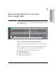
Introducing the HP ProCurve Switch zl Power Supply Shelf The HP ProCurve Switch zl Power Supply Shelf is an external power supply that can supply backup or extra Power over Ethernet (PoE/PoE+) power to the Series zl Switches. ProCurve Switch zl Power Supply Shelf J8714A PoE Power Fault Power Supply Status EPS Port Status E1 E2 Device Connected Power Status Figure 1-1.
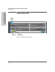
Introducing the HP ProCurve Switch zl Power Supply Shelf Front of the Unit Introducing the HP ProCurve Switch zl Power Supply Shelf Front of the Unit Power and Fault LEDs ProCurve Switch zl Power Supply Shelf J8714A PoE Power Fault Power Supply Status EPS Port Status E1 E2 Device Connected Power Status Power Status EPS Port Status Figure 1-2.
Introducing the HP ProCurve Switch zl Power Supply Shelf Front of the Unit LEDs Introducing the HP ProCurve Switch zl Power Supply Shelf Table 1-1. Power Supply Shelf LEDs LED State Meaning Power (green) Also on back panel of the Power Supply Shelf On The unit is powered on. Off The unit is NOT powered on. Fault (orange) Also on back panel of the Power Supply Shelf Off The normal state; indicates there are no fault conditions on the unit.
Introducing the HP ProCurve Switch zl Power Supply Shelf Back of the Unit Introducing the HP ProCurve Switch zl Power Supply Shelf Back of the Unit ProCurve Switch zl 875W Power Supply PoE Unit provides 273 W for PoE J8712A Power Fault EPS 1 From power supply in slot 1 Install ProCurve Switch zl Power Supplies only: 875W Power Supply, J8712A 1500W Power Supply, J8713A Install ProCurve Switch zl Power Supplies only: 875W Power Supply, J8712A 1500W Power Supply, J8713A E1 EPS 2 E2 Line: 5
Introducing the HP ProCurve Switch zl Power Supply Shelf EPS Port Operation The Power Supply Shelf supports two EPS ports that can provide power to PoE/PoE+ capable zl switches through EPS cables. Each external power supply unit can provide additional or redundant PoE/PoE+ power to a zl switch. All internal power supplies have PoE/PoE+ power. Each EPS port operates individually.
2 Installing and Connecting the External Power Supply Shelf This chapter shows you how to install the Power Supply Shelf including: ■ included parts (page 2-1) ■ installation procedures (page 2-2) ■ recommended connection topologies (page 2-12) Included Parts The Power Supply Shelf has the following components shipped with them: ■ HP ProCurve Switch zl Power Supply Shelf Installation and Getting Started Guide, this manual ■ Read Me First ■ Customer Support/Warranty booklet (5990-8862) ■ Accessory kit
Installing and Connecting the External Power Supply Shelf Installation Procedures Installation Procedures Summary Installing and Connecting the External Power Supply Shelf Follow these steps to install the Power Supply Shelf. The rest of this chapter provides details on these steps. 1. Prepare the installation site (page 2-4).
Installing and Connecting the External Power Supply Shelf Installation Procedures Installation Precautions: Follow these precautions when installing your Power Supply Shelf: WARNINGS ■ The rack or cabinet should be adequately secured to prevent it from becoming unstable and/or falling over. Devices installed in a rack or cabinet should be mounted as low as possible, with the heaviest devices at the bottom and progressively lighter devices installed above.
Installing and Connecting the External Power Supply Shelf Installation Procedures Installing and Connecting the External Power Supply Shelf 1. Prepare the Installation Site ■ Cabling - Only use the EPS cables supplied with the unit for external power connections to switches. ■ Installation Location - Before installing the unit, plan its location and orientation relative to other devices and equipment: • In both the front and back of the unit, leave at least 7.
Installing and Connecting the External Power Supply Shelf Installation Procedures 8 mm M4 screws Installing and Connecting the External Power Supply Shelf Figure 2-1. Attaching brackets to the unit WARNING For safe reliable installation, only use the screws provided in the accessory kit to attach the mounting brackets to the unit. Note The mounting brackets have multiple mounting holes and can be rotated allowing for a wide variety of mounting options.
Installing and Connecting the External Power Supply Shelf Installation Procedures 2. Partially install a screw into the top hole of a pair of holes that are 0.5 inches apart in each rack/cabinet upright as shown in the illustration below. Ensure that the screws are at the same level in each upright. Installing and Connecting the External Power Supply Shelf Partially install a screw into the top hole of a close (0.5-inch) pair on both sides of the rack Figure 2-2. Mounting screw positioning 3.
Installing and Connecting the External Power Supply Shelf Installation Procedures 4. Install the other screw into the upper hole in each bracket. Tighten these screws. Installing and Connecting the External Power Supply Shelf Figure 2-4. Installing top screws into bracket and rack Horizontal Surface Mounting Place the unit on a table or other horizontal surface. The unit comes with rubber feet in the accessory kit that can be used to help keep the unit from sliding on the surface.
Installing and Connecting the External Power Supply Shelf Installation Procedures 3. Install the Power Supplies Installing and Connecting the External Power Supply Shelf The Power Supply Shelf does not come with power supplies installed. You must purchase power supplies separately and install them. The supported power supplies are the: • HP ProCurve Switch zl Internal Power Supply, J8712A • HP ProCurve Switch zl 220V Internal Power supply, J8713A • HP ProCurve 1500W zl PoE+ Power Supply, J9306A 1.
Installing and Connecting the External Power Supply Shelf Installation Procedures 4. Connect the Power Supply Shelf to a Switch Connect the EPS cables from the supported network switches to the appropriate ports on the Power Supply Shelf. Also see “Recommended Connection Topologies” on page 2-12.
Installing and Connecting the External Power Supply Shelf Installation Procedures 5. Connect AC Power Installing and Connecting the External Power Supply Shelf Connect the AC power cord supplied with the Power Supply Shelf to the power connector on the back of the unit, and then into a properly grounded electrical outlet. Connect the AC power cord to the power connector Figure 2-6. Connecting AC power The Power Supply Shelf does not have a power switch.
Installing and Connecting the External Power Supply Shelf Installation Procedures 6. Verify Correct Operation When the Power Supply Shelf is mounted in its location and powered on, you should first verify it is working properly by checking the unit’s LEDs. Check the LEDs on the unit as described below.
Installing and Connecting the External Power Supply Shelf Recommended Connection Topologies Recommended Connection Topologies Installing and Connecting the External Power Supply Shelf This section shows some recommended connection topologies using the Power Supply Shelf. The Power Supply Shelf provides only EPS (PoE) power for up to two HP ProCurve switches.
Installing and Connecting the External Power Supply Shelf Recommended Connection Topologies To Power Source To Power Source Power Supply Shelf ProCurve Switch 5406zl ProCurve Switch 5406zl Figure 2-9. Connecting one EPS to two 5406zl switches Limitations In the illustration above, the maximum power that can be provided to each switch is dependant upon which power supply is installed in the Power Supply Shelf.
3 Troubleshooting This chapter describes how to troubleshoot the Power Supply Shelf. This chapter describes the following: ■ basic troubleshooting tips (page 3-1) ■ diagnosing with the LEDs (page 3-2) ■ diagnostic tests (page 3-4) ■ HP customer support services (page 3-4) Basic Troubleshooting Tips Most problems are caused by the following situations. Check for these items first when starting your troubleshooting: Faulty or loose cables. Look for loose or obviously faulty connections.
Troubleshooting Diagnosing with the LEDs Diagnosing with the LEDs Table 3-1 shows LED patterns on the Power Supply Shelf that indicate problem conditions. 1. Check in the table for the LED pattern that you see on your unit. 2. Refer to the corresponding diagnostic tip on the next few pages. Table 3-1.
Troubleshooting Diagnosing with the LEDs Diagnostic Tips: Problem Solution ➊ The unit is not plugged into an active AC power source, or the unit’s power supply may have failed. 1. Verify the power cord is plugged into an active power source and to the unit. Make sure these connections are snug. 2. Try power cycling the unit by unplugging and plugging the power cord back in. 3. If the Power LED is still not on, verify that the AC power source works by plugging another device into the outlet.
Troubleshooting Diagnostic Tests Diagnostic Tests Testing the Unit by Resetting It If you believe the Power Supply Shelf is not operating correctly, you can reset the unit to test its circuitry and operating code. To reset a unit, unplug and plug in the power cord (power-cycling). Caution Use caution when power cycling the unit as this may affect devices receiving operating power from the unit.
A Specifications Physical Power Supply Shelf Width: 44.3 cm (17.4 in) Depth: 22.76 cm (8.96 in) Height: 13.22 cm (5.2 in) Weight: 4.2 kg (9.2 lbs) Electrical The Power Supply Shelf automatically adjusts to any voltage between 100-127 and 200-240 volts when using the J8712A or 110-127 and 200-240 volts when using the J9306A power supplies, and 200-240 volts only when using the J8713A power supply, and either 50 or 60 Hz.
Specifications Acoustic Power Supply Shelf Geraeuschemission LwA=52.9 dB am fiktiven Arbeitsplatz nach DIN 45635 T.19 Noise Emission LwA=52.9 dB at virtual workspace according to DIN 45635 T.19 Cable Length EPS cables are 2.0 meters (6.56 feet) in length Safety Complies with: ■ EN60950 / IEC 60950 ■ CSA 22.2 No. 60950 ■ UL 60950 EMC Compliance (Class A) Complies with: ■ FCC Part 15.
B Safety and Regulatory Statements Safety and Regulatory Statements Safety Information ! Documentation reference symbol. If the product is marked with this symbol, refer to the product documentation to get more information about the product. WARNING A WARNING in the manual denotes a hazard that can cause injury or death. Caution A Caution in the manual denotes a hazard that can damage equipment.
Safety and Regulatory Statements Informations concernant la sécurité Safety and Regulatory Statements Informations concernant la sécurité ! Symbole de référence à la documentation. Si le produit est marqué de ce symbole, reportez-vous à la documentation du produit afin d'obtenir des informations plus détaillées. WARNING Dans la documentation, un WARNING indique un danger susceptible d'entraîner des dommages corporels ou la mort.
Safety and Regulatory Statements Hinweise zur Sicherheit ! Symbol für Dokumentationsverweis. Wenn das Produkt mit diesem Symbol markiert ist, schlagen Sie bitte in der Produktdokumentation nach, um mehr Informationen über das Produkt zu erhalten. WARNING Eine WARNING in der Dokumentation symbolisiert eine Gefahr, die Verletzungen oder sogar Todesfälle verursachen kann. Caution Caution in der Dokumentation symbolisiert eine Gefahr, die dis Gerät beschädigen kann.
Safety and Regulatory Statements Considerazioni sulla sicurezza Safety and Regulatory Statements Considerazioni sulla sicurezza ! Simbolo di riferimento alla documentazione. Se il prodotto è contrassegnato da questo simbolo, fare riferimento alla documentazione sul prodotto per ulteriori informazioni su di esso. WARNING La dicitura WARNING denota un pericolo che può causare lesioni o morte. Caution La dicitura Caution denota un pericolo che può danneggiare le attrezzature.
Safety and Regulatory Statements Consideraciones sobre seguridad ! Símbolo de referencia a la documentación. Si el producto va marcado con este símbolo, consultar la documentación del producto a fin de obtener mayor información sobre el producto. WARNING Una WARNING en la documentación señala un riesgo que podría resultar en lesiones o la muerte. Caution Una Caution en la documentación señala un riesgo que podría resultar en averías al equipo.
Safety and Regulatory Statements Safety Information (Japan) Safety and Regulatory Statements Safety Information (Japan) Japan Power Cord Warning B-6
Safety and Regulatory Statements Safety Information (China) Safety and Regulatory Statements Safety Information (China) B-7
Safety and Regulatory Statements EMC Regulatory Statements Safety and Regulatory Statements EMC Regulatory Statements U.S.A. FCC Class A This equipment has been tested and found to comply with the limits for a Class A digital device, pursuant to Part 15 of the FCC Rules. These limits are designed to provide reasonable protection against interference when the equipment is operated in a commercial environment.
Safety and Regulatory Statements EMC Regulatory Statements Korea Safety and Regulatory Statements Taiwan B-9
Safety and Regulatory Statements Safety and Regulatory Statements EMC Regulatory Statements B-10
C Recycle Statements Waste Electrical and Electronic Equipment (WEEE) Statements Likvidace zařízení soukromými domácími uživateli v Evropské unii Tento symbol na produktu nebo balení označuje výrobek, který nesmí být vyhozen spolu s ostatním domácím odpadem. Povinností uživatele je předat takto označený odpad na předem určené sběrné místo pro recyklaci elektrických a elektronických zařízení.
Recycle Statements Waste Electrical and Electronic Equipment (WEEE) Statements Laitteiden hävittäminen kotitalouksissa Euroopan unionin alueella Jos tuotteessa tai sen pakkauksessa on tämä merkki, tuotetta ei saa hävittää kotitalousjätteiden mukana. Tällöin hävitettävä laite on toimitettava sähkölaitteiden ja elektronisten laitteiden kierrätyspisteeseen.
Recycle Statements Waste Electrical and Electronic Equipment (WEEE) Statements Smaltimento delle apparecchiature da parte di privati nel territorio dell'Unione Europea Questo simbolo presente sul prodotto o sulla sua confezione indica che il prodotto non può essere smaltito insieme ai rifiuti domestici. È responsabilità dell'utente smaltire le apparecchiature consegnandole presso un punto di raccolta designato al riciclo e allo smaltimento di apparecchiature elettriche ed elettroniche.
Recycle Statements Waste Electrical and Electronic Equipment (WEEE) Statements Descarte de Lixo Elétrico na Comunidade Européia Este símbolo encontrado no produto ou na embalagem indica que o produto não deve ser descartado no lixo doméstico comum. É responsabilidade do cliente descartar o material usado (lixo elétrico), encaminhando-o para um ponto de coleta para reciclagem.
Index B F back of unit … 1-4 EPS ports … 1-4 power connector … 1-4 basic troubleshooting tips … 3-1 Fault LED … 1-3 behaviors … 1-3 blinking definition … 1-3 showing error conditions … 3-2 flashing LEDs error indications … 3-2 front of unit LEDs … 1-2 C cabinet mounting the unit in … 2-4 cable length specifications … A-2 cables connecting cables to the unit ports … 2-9 length … A-2 required types … 2-4 requirements … 2-4 testing … 3-4 cabling … 2-4 connecting the unit to a power source … 2-10 D E EMC
M mounting the unit in a rack or cabinet … 2-4 on a horizontal surface … 2-7 N network devices connecting to the unit … 2-9 Index P parts, included with the unit … 2-1 physical specifications, unit … A-1 port LEDs description … 1-3 ports connecting to … 2-9 connections … 2-9 location on unit … 1-4 power connector … 1-4 Power LED … 1-3 behaviors … 1-3 power source connecting the unit to … 2-10 Power Supply Status LED … 1-3 precautions mounting the unit … 2-3 power requirements … 2-3 preparing the installa
5400zl Switches Installation and Getting Startd Guide Technology for better business outcomes To learn more, visit www.hp.com/networking © Copyright 2009, 2012 Hewlett-Packard Development Company, L.P. The information contained herein is subject to change without notice. The only warranties for HP products and services are set forth in the express warranty statements accompanying such products and services. Nothing herein should be construed as constituting an additional warranty.