
HP StorageWorks SAN Director Installation Guide (A7393-90009, May 2007)


SAN Director installation guide 139
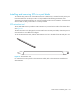
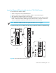
2. Connect the cables to the transceivers.
CAUTION: A 50-micron cable should not be bent to a radius less than 2 inches under full tensile
load and 1.2 inches with no tensile load. Tie wraps are not recommended for optical cables
because they are easily overtightened.
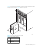
B
a. Orient a cable connector so that the key (the ridge on one side of connector) aligns with the
slot in the transceiver. Then, insert the cable into the transceiver until the latching mechanism
clicks. For instructions specific to cable type, see the cable manufacturer’s documentation.
b. Repeat Step a for the remaining cables as required.
3. Check the LEDs to verify that all components are functional.
4. Log in to the 4/256 SAN Director as admin.
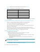
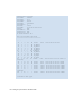
5. Verify the correct operation of the B-Series MP Router blade ports by typing the switchShow
command from the 4/256 SAN Director command prompt. This command provides information
about switch and port status.
Once the B-Series MP Router blade is installed and fully configured in a 4/256 SAN Director,
the switchShow command displays 32 Fibre Channel ports (port numbers 0 through 31) and
two GbE ports. The first 16 Fibre Channel ports are physical ports on the B-Series MP Router
blade, Ports 16-23 are virtual ports associated with the GE0 physical GbE link and ports 24-31
are virtual ports associated with GE1 physical GbE link.
The GbE ports are displayed as ge0 and ge1 and are not assigned port numbers or area
numbers. See the Example on the next page.