
FW 07.00.00/HAFM SW 08.06.00 McDATA Intrepid 6064 Director Installation and Service Manual (620-000108-920, April 2005)

3
MAP 0100: Power Distribution Analysis
3-35
Maintenance Analysis Procedures (MAPS)
2
Table 3-4 lists event codes, brief explanations of the codes, and the
associated steps that describe fault isolation procedures.
3
A redundant power supply is disconnected from facility power, not
properly installed, or has failed.
Verify the power supply is connected to facility power.
a. Ensure the AC power cord associated with the power supply
(PS0 or PS1) is connected to the rear of the director and a facility
power receptacle. If not, connect the cord as directed by the
customer.
b. Ensure the associated facility circuit breaker is on. If not, ask the
customer set the circuit breaker on.
c. Ensure the AC power cord is not damaged. If damaged, replace
the cord.
Was a corrective action performed?
YES NO
↓ Go to step 5.
4
Verify redundant power supply operation.
a. Inspect the power supply and ensure the green PWR OK LED
illuminates and all amber LEDs extinguish.
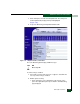
b. At the management server Hardware View, observe the graphic
representing the power supply and ensure a failure symbol
(blinking red and yellow diamond) does not appear.
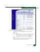
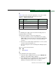
Table 3-4 MAP 100: Event Codes
Event
Code
Explanation Action
200 Power supply AC voltage failure. Go to step 3.
201 Power supply DC voltage failure. Go to step 3.
202 Power supply thermal failure. Go to step 7.
208 Power supply false shutdown. Go to step 8.