
FW 07.00.00/HAFM SW 08.06.00 McDATA Intrepid 6064 Director Installation and Service Manual (620-000108-920, April 2005)


5
5-6
Intrepid® 6064 Director Installation and Service Manual
Removal and Replacement Procedures (RRPs)
— If the director is installed in a customer-supplied equipment
cabinet, unlock and open the cabinet front door as directed by
the customer representative.
2. If fiber-optic and Ethernet cables are attached to the director,
disengage the cables from the cable management assembly, then
lift the cables up and out of the assembly.
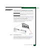
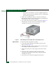
3. Two captive pins secure the assembly to the chassis (Figure 5-3).
Pull both pins inward to release the assembly, then pull the
assembly away from the front of the director.
.
Figure 5-3 Cable Management Assembly Removal and Replacement
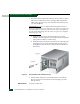
Replacement To replace the cable management assembly:
1. Position the cable management assembly at the front of the
director chassis (Figure 5-3).
2. Disengage both captive pins by pulling them inward, then push
the assembly toward the card cage area.
3. Release the captive pins so they engage in the chassis anchor
points.
4. Route fiber-optic and Ethernet cables through the cable
management assembly. Dress the cables evenly through the
assembly cut-out slots.
5. If necessary, close and lock the equipment cabinet door.