
FW 07.00.00/HAFM SW 08.06.00 McDATA Intrepid 6064 Director Installation and Service Manual (620-000108-920, April 2005)


5
RRP: CTP2 Card
5-7
Removal and Replacement Procedures (RRPs)
RRP: CTP2 Card
Use the following procedures to remove or replace a CTP2 card (two
cards in the director) with the backup CTP2 card operational. A list of
tools required is provided.
ATTENTION! Do not remove and replace a CTP2 card if the backup CTP2
card is not fully operational and director power is on. The director IP address,
configuration data, and other operating parameters will be lost.
Tools Required The following tools are required to perform these procedures.
• Door key with 5/16-inch socket (provided with the FC-512
Fabricenter equipment cabinet).
• ESD grounding cable and wrist strap.
• Torque tool and hex adapter (provided with the director).
Removal To remove a CTP2 card:
1. If the director is installed in a stand-alone configuration, go to
step 2. If the director is rack-mounted, perform one of the
following:
— If the director is installed in a McDATA-supplied FC-512
Fabricenter equipment cabinet, insert the 5/16” door tool into
the socket hole at the right top of the front door. Turn the tool
counter-clockwise to unlock and open the door.
— If the director is installed in a customer-supplied equipment
cabinet, unlock and open the cabinet front door as directed by
the customer representative.
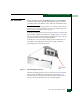
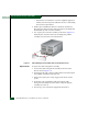
2. Follow ESD procedures by attaching a wrist strap to the director
chassis and your wrist (Figure 5-1).
ATTENTION! To avoid causing machine errors or damage while working on
the director, follow ESD procedures by connecting a grounding cable to the
director chassis and wearing an ESD wrist strap.
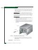
3. Identify the defective CTP2 card from the amber LED on the card
or failure information at the management server Hardware View.
4. Disconnect the Ethernet local area network (LAN) cable from the
RJ-45 connector on the card faceplate.