
FW 07.00.00/HAFM SW 08.06.00 McDATA Intrepid 6064 Director Installation and Service Manual (620-000108-920, April 2005)


5
RRP: Optical Transceiver (SFP and XFP)
5-19
Removal and Replacement Procedures (RRPs)
3. Perform an external loopback test for the port (Performing Port
Diagnostic Loopback Tests on page 4-30). If the test fails, go to MAP
0000: Start MAP on page 3-9 to isolate the problem.
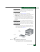
4. Reconnect the fiber-optic jumper cable:
a. Remove the protective cap from the cable connector and the
protective plug from the port optical transceiver. Store the cap
and plug in a suitable location for safekeeping.
b. Clean the cable and port connectors (Cleaning Fiber-Optic
Components on page 4-51).
c. Insert the keyed LC cable connector into port optical transceiver.
5. Disconnect the ESD wrist strap from the director chassis and your
wrist.
6. Inspect the port card with the replacement port transceiver to
ensure all amber LEDs are extinguished. If any amber LEDs are
illuminated, go to MAP 0000: Start MAP on page 3-9 to isolate the
problem.
7. At the management server or at a web browser connected to the
SANpilot interface, inspect the Event Log. Ensure an event code
510 (SFP/XFP optics card hot-insertion initiated) appears in the
log.
If an event code 510 does not appear in the log, go to MAP 0000:
Start MAP on page 3-9 to isolate the problem.
8. Perform one of the following to verify port card operation:
— If at the management server, open the Hardware View and
observe the port card graphic to ensure no alert symbols
appear that indicate a failure (yellow triangle or red diamond).
If a problem is indicated, go to MAP 0000: Start MAP on
page 3-9 to isolate the problem.
— If at a web browser connected to the SANpilot interface, open
the Switch tab at the View panel and ensure no amber LEDs
illuminate that indicate a port card failure. If a problem is
indicated, go to MAP 0000: Start MAP on page 3-9 to isolate
the problem.
If a problem is indicated, go to MAP 0000: Start MAP on page 3-9
to isolate the problem.