
FW 07.00.00/HAFM SW 08.06.00 McDATA Intrepid 6064 Director Installation and Service Manual (620-000108-920, April 2005)

5
5-30
Intrepid® 6064 Director Installation and Service Manual
Removal and Replacement Procedures (RRPs)
b. Click the Sys Err Light tab. The Switch page displays with
the Sys Err Light tab selected. A System Error Light is ON
message displays on the page.
c. Click Clear Light.
13. If necessary, close and lock the equipment cabinet door.
RRP: Fan Module
Use the following procedures to remove or replace a fan module. A
list of tools required is provided.
Tools Required The following tools are required to perform these procedures.
• Door key with 5/16-inch socket (provided with the FC-512
Fabricenter equipment cabinet).
• Standard flat-tip screwdriver.
• ESD grounding cable and wrist strap.
Removal To remove a fan module:
1. If the director is installed in a stand-alone configuration, go to
step 2. If the director is rack-mounted, perform one of the
following:
— If the director is installed in a McDATA-supplied FC-512
Fabricenter equipment cabinet, insert the 5/16" door tool into
the socket hole at the right top of the rear door. Turn the tool
counter-clockwise to unlock and open the door.
— If the director is installed in a customer-supplied equipment
cabinet, unlock and open the cabinet rear door as directed by
the customer representative.
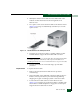
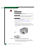
2. Follow ESD procedures by attaching a wrist strap to the director
chassis and your wrist (Figure 5-2).
ATTENTION! To avoid causing machine errors or damage while working on
the director, follow ESD procedures by connecting a grounding cable to the
director chassis and wearing an ESD wrist strap.
3. Remove the RFI shield (RRP: RFI Shield on page 5-25).