
FW 07.00.00/HAFM SW 08.06.00 McDATA Intrepid 6064 Director Installation and Service Manual (620-000108-920, April 2005)

5
RRP: Fan Module
5-31
Removal and Replacement Procedures (RRPs)
4. Identify the defective fan module from the amber LED on the
module or failure information at the management server
Hardware View.
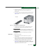
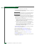
5. Two captive screws secure the fan module to the director chassis
(Figure 5-12). Using a standard flat-tip screwdriver, loosen the
captive screws.
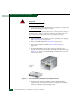
Figure 5-12 Fan Module Removal and Replacement
6. Using the rear of the fan module as a handle, pull the module
from the director. Support the fan module with one hand.
ATTENTION! Do not remove a fan module unless the replacement module
is available. Operation of the director with only one fan module for an
extended period may cause one or more thermal sensors to post event codes.
7. Place the fan module in an anti-static bag to provide ESD
protection.
Replacement To replace the fan module:
1. Remove the replacement fan module from its protective
anti-static bag.
2. Inspect the PWA on the underside of the fan module for bent or
broken connector pins that may have been damaged during
shipping. If any pins are damaged, obtain a new fan module.
3. Position the fan module at the rear of the director chassis
(Figure 5-12). Using the rear of the fan module as a handle, push
the module toward the backplane to engage the connector pins.
Support the fan module with one hand.