
FW 07.00.00/HAFM SW 08.06.00 McDATA Intrepid 6064 Director Installation and Service Manual (620-000108-920, April 2005)

5
5-32
Intrepid® 6064 Director Installation and Service Manual
Removal and Replacement Procedures (RRPs)
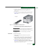
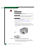
4. Using a standard flat-tip screwdriver, tighten the two captive
screws that secure the fan module to the director chassis.
5. Disconnect the ESD wrist strap from the director chassis and your
wrist.
6. Inspect the fan module to ensure the amber LED is extinguished.
If the LED is illuminated, go to MAP 0000: Start MAP on page 3-9
to isolate the problem.
7. At the management server or at a web browser connected to the
SANpilot interface, inspect the Event Log. Ensure an event code
321 (fan FRU inserted) appears in the log.
If an event code 321 does not appear in the log, go to MAP 0000:
Start MAP on page 3-9 to isolate the problem.
8. Perform one of the following to verify fan module operation:
— If at the management server, open the Hardware View and
observe the fan module graphic to ensure no alert symbols
appear that indicate a failure (yellow triangle or red diamond).
If a problem is indicated, go to MAP 0000: Start MAP on
page 3-9 to isolate the problem.
— If at a web browser connected to the SANpilot interface, open
the Switch tab at the View panel and ensure no amber LEDs
illuminate that indicate a fan module failure. If a problem is
indicated, go to MAP 0000: Start MAP on page 3-9 to isolate
the problem.
9. Replace the RFI shield (RRP: RFI Shield on page 5-25).
10. Perform the data collection procedure (Collecting Maintenance
Data on page 4-39).
11. Perform one of the following to clear the system error (ERR) LED:
— If at the management server, open the Hardware View and:
a. Right-click the front panel bezel graphic (away from a
FRU) to open a menu.
b. Click the Clear System Error Light menu selection.
— If at a web browser connected to the SANpilot interface:
a. Click the Switch tab at the Operations panel. The Operations
panel opens with the Switch page displayed.