
FW 07.00.00/HAFM SW 08.06.00 McDATA Intrepid 6064 Director Installation and Service Manual (620-000108-920, April 2005)

5
RRP: Power Module Assembly
5-33
Removal and Replacement Procedures (RRPs)
b. Click the Sys Err Light tab. The Switch page displays with
the Sys Err Light tab selected. A System Error Light is ON
message displays on the page.
c. Click Clear Light.
12. If necessary, close and lock the equipment cabinet door.
RRP: Power Module Assembly
Use the following procedures to remove or replace the power module
assembly. A list of tools required is provided.
Tools Required The following tools are required to perform these procedures.
• Door key with 5/16-inch socket (provided with the FC-512
Fabricenter equipment cabinet).
• Standard flat-tip screwdriver.
• Standard cross-tip (Phillips) screwdriver.
• ESD grounding cable and wrist strap.
Removal To remove the power module assembly:
1. Notify the customer the director will be powered off. Ensure the
customer system administrator quiesces Fibre Channel frame
traffic through the director and sets attached devices offline.
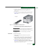
2. If the director is installed in a stand-alone configuration, go to
step 3. If the director is rack-mounted, perform one of the
following:
— If the director is installed in a McDATA-supplied FC-512
Fabricenter equipment cabinet, insert the 5/16” door tool into
the socket hole at the right top of the front door. Turn the tool
counter-clockwise to unlock and open the door. Repeat this
step to open the rear door.
— If the director is installed in a customer-supplied equipment
cabinet, unlock and open the cabinet front door as directed by
the customer representative. Repeat this step to open the rear
door.
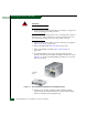
3. Power off and unplug the director (Power-Off Procedure on
page 4-53).