
FW 07.00.00/HAFM SW 08.06.00 McDATA Intrepid 6064 Director Installation and Service Manual (620-000108-920, April 2005)

5
5-34
Intrepid® 6064 Director Installation and Service Manual
Removal and Replacement Procedures (RRPs)
DANGER
Disconnect the power cords.
4. Follow ESD procedures by attaching a wrist strap to an approved
bench grounding point and your wrist.
ATTENTION! To avoid causing machine errors or damage while working on
the director, follow ESD procedures by connecting a grounding cable to an
approved bench grounding point and wearing an ESD wrist strap.
5. Unseat and disconnect (but do not remove) both power supplies
(RRP: Power Supply on page 5-22).
6. Remove the RFI shield (RRP: RFI Shield on page 5-25).
7. Remove both SBAR assemblies (RRP: SBAR Assembly on
page 5-26).
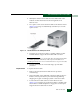
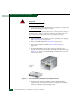
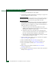
8. Six panhead Phillips screws (two at the top and four at the
bottom) secure the power module assembly to the director chassis
(Figure 5-13). Using a standard Phillips screwdriver, loosen and
remove the screws.
Figure 5-13 Power Module Assembly Removal and Replacement
9. Pull the power module assembly (with the SBAR assembly
support shelf) out of the director chassis. Support the assembly
with one hand when performing this step.