
FW 07.00.00/HAFM SW 08.06.00 McDATA Intrepid 6064 Director Installation and Service Manual (620-000108-920, April 2005)

5
RRP: Power Module Assembly
5-35
Removal and Replacement Procedures (RRPs)
10. Place the power module assembly in an anti-static bag to provide
ESD protection.
Replacement To replace the power module assembly:
1. Remove the replacement power module assembly from its
protective anti-static bag.
2. Inspect the PWA side of the power module assembly for bent or
broken connector pins that may have been damaged during
shipping. If any pins are damaged, obtain a new assembly.
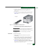
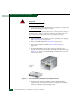
3. Position the power module assembly at the rear of the director
chassis (Figure 5-13). Push the module toward the backplane to
engage the connector pins. Support the fan module with one
hand when performing this step.
4. Using a standard Phillips screwdriver, insert and tighten the six
panhead Phillips screws that secure the power module assembly.
5. Replace both SBAR assemblies (RRP: SBAR Assembly on
page 5-26).
6. Replace the RFI shield (RRP: RFI Shield on page 5-25.
7. Seat and connect both power supplies (RRP: Power Supply on
page 5-22).
8. Disconnect the ESD wrist strap from the director chassis and your
wrist.
9. Power on the director (Power-On Procedure on page 4-52).
10. Verify that power-on self-tests (POSTs) complete and the green
power LED on the front bezel, green LED on the active CTP2
card, and green PWR OK LEDs on both power supplies remain
illuminated. If a problem is indicated, go to MAP 0000: Start MAP
on page 3-9 to isolate the problem.
11. Perform one of the following to verify power module assembly
operation:
— If at the management server, open the Hardware View and
observe the power module assembly graphics to ensure no
alert symbols appear that indicate a failure (yellow triangle or
red diamond). If a problem is indicated, go to MAP 0000: Start
MAP on page 3-9 to isolate the problem.