
FW 07.00.00/HAFM SW 08.06.00 McDATA Intrepid 6064 Director Installation and Service Manual (620-000108-920, April 2005)

5
5-36
Intrepid® 6064 Director Installation and Service Manual
Removal and Replacement Procedures (RRPs)
— If at a web browser connected to the SANpilot interface, open
the Switch tab at the View panel and ensure no amber LEDs
illuminate that indicate FRU failure. If a problem is indicated,
go to MAP 0000: Start MAP on page 3-9 to isolate the problem.
12. Perform the data collection procedure (Collecting Maintenance
Data on page 4-39).
13. Perform one of the following to clear the system error (ERR) LED:
— If at the management server, open the Hardware View and:
a. Right-click the front panel bezel graphic (away from a
FRU) to open a menu.
b. Click the Clear System Error Light menu selection.
— If at a web browser connected to the SANpilot interface:
a. Click the Switch tab at the Operations panel. The Operations
panel opens with the Switch page displayed.
b. Click the Sys Err Light tab. The Switch page displays with
the Sys Err Light tab selected. A System Error Light is ON
message displays on the page.
c. Click Clear Light.
14. If necessary, close and lock the equipment cabinet door.
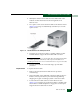
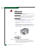
RRP: Backplane
Use the following procedures to remove or replace the backplane. A
list of tools required is provided.
Tools Required The following tools are required to perform these procedures.
• Door key with 5/16-inch socket (provided with the FC-512
Fabricenter equipment cabinet).
• Torque tool and hex adapter (provided with the director).
• Standard flat-tip screwdriver.
• Standard cross-tip (Phillips) screwdriver.
• ESD grounding cable and wrist strap.
• Maintenance terminal (desktop or notebook PC) with: