
FW 07.00.00/HAFM SW 08.06.00 McDATA Intrepid 6064 Director Installation and Service Manual (620-000108-920, April 2005)

5
5-38
Intrepid® 6064 Director Installation and Service Manual
Removal and Replacement Procedures (RRPs)
5. If necessary, record the director serial number.
6. Follow ESD procedures by attaching a wrist strap to an approved
bench grounding point and your wrist.
ATTENTION! To avoid causing machine errors or damage while working on
the director, follow ESD procedures by connecting a grounding cable to an
approved bench grounding point and wearing an ESD wrist strap.
7. Unseat and disconnect all logic cards (CTP2 and port cards) from
the backplane. Unseat the cards only, do not remove them from
the director chassis. In addition, do not disconnect the Ethernet or
fiber-optic cables. For each logic card:
a. Insert the torque tool into the locking Allen screw at the
bottom of the card. Turn the screw counter-clockwise until the
spring releases and the tool turns freely.
b. Insert the torque tool into the Allen screw at the top of the
card. To unseat the card and cam it out of the backplane, turn
the screw counterclockwise until the tool turns freely.
c. Disconnect the card from the backplane by pulling it out of the
card track approximately two inches.
8. Unseat and disconnect (but do not remove) both power supplies
(RRP: Power Supply on page 5-22).
9. Remove the RFI shield (RRP: RFI Shield on page 5-25).
10. Remove both fan modules (RRP: Fan Module on page 5-30).
11. Remove both SBAR assemblies (RRP: SBAR Assembly on
page 5-26).
12. Remove the power module assembly (RRP: Power Module
Assembly on page 5-33).
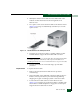
13. The backplane is secured to the director chassis with 11 panhead
Phillips screws (Figure 5-14).