
FW 07.00.00/HAFM SW 08.06.00 McDATA Intrepid 6064 Director Installation and Service Manual (620-000108-920, April 2005)

5
5-40
Intrepid® 6064 Director Installation and Service Manual
Removal and Replacement Procedures (RRPs)
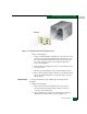
c. While holding the backplane in place, insert and hand tighten
one of the top center panhead Phillips screws.
d. Insert and hand tighten the remaining ten panhead Phillips
screws. Tighten the screws alternately from bottom to top and
from side to side.
e. Using a standard Phillips screwdriver, tighten the 11 panhead
screws that secure the backplane to the chassis. Tighten the screws
alternately from bottom to top and from side to side.
2. Replace the power module assembly (RRP: Power Module
Assembly on page 5-33).
3. Replace both SBAR assemblies (RRP: SBAR Assembly on
page 5-26).
4. Replace both fan modules (RRP: Fan Module on page 5-30).
5. Replace the RFI shield (RRP: RFI Shield on page 5-25).
6. Seat and connect both power supplies (RRP: Power Supply on
page 5-22).
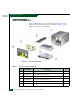
7. Seat all logic cards (CTP2 and port cards) into the backplane. For
each logic card:
a. Slide the card forward until it makes contact with the
backplane.
b. Insert the torque tool into the Allen screw at the top of the
card. Turn the torque tool clockwise until you feel it release
and hear a clicking sound. As the screw turns clockwise, the
card cams into the backplane connector.
c. Insert the torque tool into the locking Allen screw at the
bottom of the card. Turn the torque tool clockwise until you
feel it release and hear a clicking sound. As the screw turns
clockwise, the card locks into place.
d. Verify the card stiffener is flush with the front of the card cage
and even with other director logic cards.
8. Disconnect the ESD wrist strap from the director chassis and your
wrist.
9. Power on the director (Power-On Procedure on page 4-52).