
FW 07.00.00/HAFM SW 08.06.00 McDATA Intrepid 6064 Director Installation and Service Manual (620-000108-920, April 2005)

5
RRP: Backplane
5-41
Removal and Replacement Procedures (RRPs)
10. Verify that POSTs complete and the green power LED on the front
bezel, green LED on the active CTP2 card, and green PWR OK
LEDs on both power supplies remain illuminated. If a problem is
indicated, go to MAP 0000: Start MAP on page 3-9 to isolate the
problem.
11. Reprogram the replacement backplane with the original director
serial number:
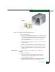
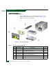
a. Remove the protective cap from the 9-pin maintenance port at
the rear of the director (a flat-tip screwdriver may be
required). Connect the 9-pin end of the RS-232 modem cable to
the port.
b. Connect the other cable end to a 9-pin communication port
(COM1 or COM2) at the rear of the maintenance terminal PC.
c. Power on the maintenance terminal. After the PC powers on,
the Windows desktop displays. If required, refer to operating
instructions shipped with the PC and return here.
d. At the Windows desktop, click Start at the left side of the task
bar. The Windows Workstation menu displays.
NOTE: The following steps describe changing network addresses
using HyperTerminal serial communication software.
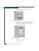
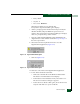
e. At the Windows Workstation menu, sequentially select
Programs, Accessories, Hyperterminal, and HyperTerminal. The
Connection Description dialog box displays (Figure 5-15).
Figure 5-15 Connection Description Dialog Box