
FW 07.00.00/HAFM SW 08.06.00 McDATA Intrepid 6064 Director Installation and Service Manual (620-000108-920, April 2005)

5
5-44
Intrepid® 6064 Director Installation and Service Manual
Removal and Replacement Procedures (RRPs)
o. Disconnect the RS-232 modem cable from the director and
the maintenance terminal. Replace the protective cap over the
maintenance port.
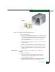
12. Initial machine load (IML) the director. At the front of the
director, press and hold the white IML button on the faceplate of
the active CTP2 card (green LED illuminated) for three seconds.
13. At the management server Hardware View, observe all FRU
graphics and ensure no alert symbols appear that indicate a
failure (yellow triangle or red diamond). If a problem is indicated,
go to MAP 0000: Start MAP on page 3-9 to isolate the problem.
14. Perform the data collection procedure (Collecting Maintenance
Data on page 4-39).
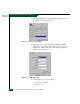
15. Perform one of the following to clear the system error (ERR) LED:
— If at the management server, open the Hardware View and:
a. Right-click the front panel bezel graphic (away from a
FRU) to open a menu.
b. Click the Clear System Error Light menu selection.
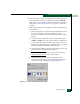
— If at a web browser connected to the SANpilot interface:
a. Click the Switch tab at the Operations panel. The Operations
panel opens with the Switch page displayed.
b. Click the Sys Err Light tab. The Switch page displays with
the Sys Err Light tab selected. A System Error Light is ON
message displays on the page.
c. Click Clear Light.
16. If necessary, close and lock the equipment cabinet doors.