
FW 07.00.00/HAFM SW 08.06.00 McDATA Intrepid 6064 Director Installation and Service Manual (620-000108-920, April 2005)


2
2-14
Intrepid® 6064 Director Installation and Service Manual
Installation Tasks
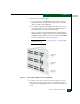
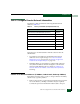
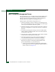
Figure 2-4 AC Power Connections (Director)
3. Connect the equipment rack power cords to separate (for
redundancy) facility power sources that provide single-phase, 120
to 240 VAC voltage.
4. Power on the rack power strips.
5. Inspect the front panel of each rack-mounted Ethernet hub.
Ensure each green Power LED illuminates.
6. At the bottom rear of the director, set the power switch (circuit
breaker) to the up position. The director powers on and performs
POSTs. During POSTs:
— Amber LEDs on both CTP2 cards and all port cards illuminate
momentarily.
— The green LED on each CTP2 card (active and backup) and
each port card illuminate as the card is tested.
— Green LEDs associated with Fibre Channel ports sequentially
illuminate as the ports are tested.
7. After successful POST completion
— Bezel: POWER LED green
— Active CTP2 card: LED green
— Power supplies: PWR OK LEDs green
8. If a POST error or other malfunction occurs, go to Chapter 3,
Maintenance Analysis Procedures (MAPS) to isolate the problem.