
FW V06.XX/HAFM SW V08.02.00 HP StorageWorks Director Element Manager User Guide (AA-RTDUC-TE, July 2004)
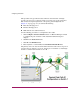
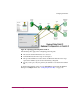
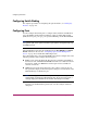
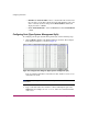
Table Of Contents
- Contents
- About this Guide
- Overview
- Feature Keys
- Managing the Director
- Element Manager Description
- Using the Element Manager
- Backing Up and Restoring Element Manager Data
- Monitoring and managing the Director
- Hardware View
- Port Card View
- Port List View
- Node List View
- Performance View
- FRU List View
- Port Operational States
- Link Incident Alerts
- Threshold Alerts
- Configuring the Director
- Configuring Identification
- Configuring Management Style
- Configuring Operating Parameters
- Configuring a Preferred Path
- Configuring Switch Binding
- Configuring Ports
- Configuring Port Addresses (FICON Management Style)
- Configuring an SNMP Agent
- Configuring Open Systems Management Server
- Configuring FICON Management Server
- Configuring Feature Key
- Configuring Date and Time
- Configuring Threshold Alerts
- Creating New Alerts
- Figure 49: Configure Threshold Alert(s) dialog box
- Figure 50: New Threshold Alerts dialog box - first screen
- Figure 51: New Threshold Alerts dialog box - second screen
- Figure 52: New Threshold Alerts dialog box - third screen
- Figure 53: New Threshold Alerts dialog box - summary screen
- Figure 54: Configure Threshold Alerts dialog box - alert activated
- Modifying Alerts
- Activating or Deactivating Alerts
- Deleting Alerts
- Creating New Alerts
- Configuring Open Trunking
- Exporting the Configuration Report
- Enabling Embedded Web Server
- Enabling Telnet
- Backing Up and Restoring Configuration Data
- Using Logs
- Using Maintenance Features
- Optional Features
- Information and Error Messages
- Index

Configuring the Director
135Director Element Manager User Guide
When you change a port’s speed and click Activate on the dialog box, a
confirmation message displays stating that this setting will temporarily disrupt
port data transfers.
Note: Your director model, firmware, and port cards may not allow 2 Gig data
speeds.
■ Bound WWN—Enter the WWN or nickname of the device that is attached to
the port.
If the check box in the Port Binding column is checked and a WWN is
entered in the Bound WWN field, only the specified device can attach to the
port.
If the check box in the Port Binding column is checked but no WWN is
entered in the Bound WWN field, no device can connect to the port.
If the check box in the Port Binding column is not checked, any device can
connect to the port (provided that the port type matches and the check box in
the Blocked column is not checked). Any WWN or nickname entered in the
Bound WWN field is stored.
When you click Activate, if the check box in the Port Binding column is
checked and the WWN or nickname in the Port Binding column does not
match the device actually connected to the port, the warning dialog box
displays. If you click Continue, the currently attached devices are logged off.
Warnings and Error Messages
If you click Activate when any node attached to a port does not match the WWN
or nickname in that port’s Bound WWN column, a Warning! dialog box displays.
If you click Continue, all nodes listed will be logged off, and the ports will attach
to the respective devices identified in the Bound WWN column.
If you click Activate when the format for the WWN or nickname in the Bound
WWN column is not valid, an error message displays. For example, The WWN
is not in the xx.xx.xx.xx.xx.xx.xx.xx format.