
FW V06.XX/HAFM SW V08.02.00 HP StorageWorks Director Element Manager User Guide (AA-RTDUC-TE, July 2004)
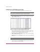

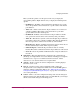

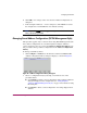
Table Of Contents
- Contents
- About this Guide
- Overview
- Feature Keys
- Managing the Director
- Element Manager Description
- Using the Element Manager
- Backing Up and Restoring Element Manager Data
- Monitoring and managing the Director
- Hardware View
- Port Card View
- Port List View
- Node List View
- Performance View
- FRU List View
- Port Operational States
- Link Incident Alerts
- Threshold Alerts
- Configuring the Director
- Configuring Identification
- Configuring Management Style
- Configuring Operating Parameters
- Configuring a Preferred Path
- Configuring Switch Binding
- Configuring Ports
- Configuring Port Addresses (FICON Management Style)
- Configuring an SNMP Agent
- Configuring Open Systems Management Server
- Configuring FICON Management Server
- Configuring Feature Key
- Configuring Date and Time
- Configuring Threshold Alerts
- Creating New Alerts
- Figure 49: Configure Threshold Alert(s) dialog box
- Figure 50: New Threshold Alerts dialog box - first screen
- Figure 51: New Threshold Alerts dialog box - second screen
- Figure 52: New Threshold Alerts dialog box - third screen
- Figure 53: New Threshold Alerts dialog box - summary screen
- Figure 54: Configure Threshold Alerts dialog box - alert activated
- Modifying Alerts
- Activating or Deactivating Alerts
- Deleting Alerts
- Creating New Alerts
- Configuring Open Trunking
- Exporting the Configuration Report
- Enabling Embedded Web Server
- Enabling Telnet
- Backing Up and Restoring Configuration Data
- Using Logs
- Using Maintenance Features
- Optional Features
- Information and Error Messages
- Index

Configuring the Director
142 Director Element Manager User Guide
Configuring Port Addresses (FICON Management Style)
This procedure applies only to a director that is using FICON Management Style.
Use this procedure to create and activate port address configurations in the
Configure Address - “Active” dialog box (see Figure 41 on page 144.)
Parameters
■ Addr—This read-only field lists the port’s address. Each port in the switch
has a corresponding port address which equals the physical port number plus
four. Therefore, the address for port 0 is 4 (0+4).
■ Port Name—This user-defined name is assigned to the address. Up to 24
alphanumeric characters are allowed, including spaces, hyphens, and
underscores.
■ Blocked—If the box is checked, the port is blocked. Blocked ports
continuously transmit offline sequences (OLS), but cannot communicate to an
attached device. If the box is not checked, the port is unblocked.
■ Port connection array—This yellow area of the dialog box is a matrix of
port addresses that is used to configure connections between port addresses.
All port addresses for the director are listed along the top and left side of the
matrix. To allow or prohibit connections between two addresses, click the cell
at the intersection of a vertical and horizontal row of cells. Right-click the
intersecting cell to display a menu of attributes.
Note: For the Director 2/140, port addresses 84–87 contain Xs. These refer to the
internal ports 128–131, which cannot have external fiber cable connections.
The default state of a cell is an empty cell (square), which represents an
allowed connection. The symbol for a prohibited connection is shown in
Figure 40. Click a cell to add the prohibited symbol and prohibit connection
to that cell. To remove the prohibit symbol, click the cell again.
Figure 40: Prohibited Port connection symbol