
FW V06.XX/HAFM SW V08.02.00 HP StorageWorks Director Element Manager User Guide (AA-RTDUC-TE, July 2004)

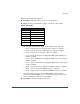

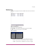


Table Of Contents
- Contents
- About this Guide
- Overview
- Feature Keys
- Managing the Director
- Element Manager Description
- Using the Element Manager
- Backing Up and Restoring Element Manager Data
- Monitoring and managing the Director
- Hardware View
- Port Card View
- Port List View
- Node List View
- Performance View
- FRU List View
- Port Operational States
- Link Incident Alerts
- Threshold Alerts
- Configuring the Director
- Configuring Identification
- Configuring Management Style
- Configuring Operating Parameters
- Configuring a Preferred Path
- Configuring Switch Binding
- Configuring Ports
- Configuring Port Addresses (FICON Management Style)
- Configuring an SNMP Agent
- Configuring Open Systems Management Server
- Configuring FICON Management Server
- Configuring Feature Key
- Configuring Date and Time
- Configuring Threshold Alerts
- Creating New Alerts
- Figure 49: Configure Threshold Alert(s) dialog box
- Figure 50: New Threshold Alerts dialog box - first screen
- Figure 51: New Threshold Alerts dialog box - second screen
- Figure 52: New Threshold Alerts dialog box - third screen
- Figure 53: New Threshold Alerts dialog box - summary screen
- Figure 54: Configure Threshold Alerts dialog box - alert activated
- Modifying Alerts
- Activating or Deactivating Alerts
- Deleting Alerts
- Creating New Alerts
- Configuring Open Trunking
- Exporting the Configuration Report
- Enabling Embedded Web Server
- Enabling Telnet
- Backing Up and Restoring Configuration Data
- Using Logs
- Using Maintenance Features
- Optional Features
- Information and Error Messages
- Index

Using Logs
171Director Element Manager User Guide
Each log entry includes the following:
■ Date/Time—The date and time of the event on the director
■ Event—Events are identified by a unique code. Event codes include:
The following acronyms may display in this column for the port card:
— GLSL—G_Port, long wave, single-mode LC connector, 1 Gigabit
— GSML—G_Port, short wave, multi-mode, LC connector, 1 Gigabit
— GXXL—G_Port, mixed mode, LC connector, 1 Gigabit
— FPM—G_Port, small form factor pluggable (SFP) optics, FICON port
module, 1 Gigabit
— UPM—G_Port, small form factor pluggable (SFP) optics, universal port
module, 2 Gigabit
— GSF2—G_Port, small form factor pluggable (SFP) optics, universal port
module, 2 Gigabit
— GLSR—G_Port, short wave, single-mode, MT-RJ connector, 1 Gigabit
— GXXR—G_Port, mixed mode, MT-RJ connector, 1 Gigabit
— GSMR—G_Port, short wave, multi-mode, MT-RJ connector, 1 Gigabit
The chassis (slot) position for a non-redundant FRU is 0. The chassis
positions for redundant FRUs are 0, 1, and 2. The chassis positions for port
cards are 0 through 35, and slot 32 is unavailable.
■ Description—A short description of the event
Table 5: Event codes
Code Event
000–199 System events
200–299 Power supply events
300–399 Fan module events
400–499 CTP card events
500–599 Port card events
600–699 SBAR card events
800–899 Thermal events