
FW V06.XX/HAFM SW V08.02.00 HP StorageWorks Director Element Manager User Guide (AA-RTDUC-TE, July 2004)


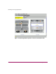

Table Of Contents
- Contents
- About this Guide
- Overview
- Feature Keys
- Managing the Director
- Element Manager Description
- Using the Element Manager
- Backing Up and Restoring Element Manager Data
- Monitoring and managing the Director
- Hardware View
- Port Card View
- Port List View
- Node List View
- Performance View
- FRU List View
- Port Operational States
- Link Incident Alerts
- Threshold Alerts
- Configuring the Director
- Configuring Identification
- Configuring Management Style
- Configuring Operating Parameters
- Configuring a Preferred Path
- Configuring Switch Binding
- Configuring Ports
- Configuring Port Addresses (FICON Management Style)
- Configuring an SNMP Agent
- Configuring Open Systems Management Server
- Configuring FICON Management Server
- Configuring Feature Key
- Configuring Date and Time
- Configuring Threshold Alerts
- Creating New Alerts
- Figure 49: Configure Threshold Alert(s) dialog box
- Figure 50: New Threshold Alerts dialog box - first screen
- Figure 51: New Threshold Alerts dialog box - second screen
- Figure 52: New Threshold Alerts dialog box - third screen
- Figure 53: New Threshold Alerts dialog box - summary screen
- Figure 54: Configure Threshold Alerts dialog box - alert activated
- Modifying Alerts
- Activating or Deactivating Alerts
- Deleting Alerts
- Creating New Alerts
- Configuring Open Trunking
- Exporting the Configuration Report
- Enabling Embedded Web Server
- Enabling Telnet
- Backing Up and Restoring Configuration Data
- Using Logs
- Using Maintenance Features
- Optional Features
- Information and Error Messages
- Index

Monitoring and managing the Director
62 Director Element Manager User Guide
Hardware View
Using this graphical view of the director, you can view status symbols and
simulated light emitting diode (LED) indicators, display data. You can also use
mouse functions to monitor status and obtain vital product information for the
director and its hardware components. To display the Hardware View, choose
Hardware from the view tabs on the Element Manager window.
Identifying FRUs
Move the mouse pointer over parts of the director graphic in the Hardware View to
display labels identifying each hardware component and its slot position in the
chassis relative to identical components installed in the director. Components
include:
■ Port cards.
— The Director 2/64 can contain up to 16 port cards, slot positions 15
through 0 (left to right).
— The Director 2/140 can contain up to 32 port cards in the front of the unit
(slot positions 0–1) and up to three additional port cards in the rear (slot
positions 33–35). Note that blank slot position 32 relates to ports
128–131, which are internal ports.
As you move the mouse pointer over each card, labels display, identifying the
card's slot number and port technology. Acronyms that may display to identify
port technology, such as UPM, GSML, GXXL, FPM, UPM, GLSR, GSMR,
GLSL, and GXXR, also display in the FRU column of the FRU List View.
See “FRU List View” on page 107 for details.
■ Control processor (CTP) cards. Two CTP cards are installed, slot positions 1
and 0 (left to right).
■ Power supply modules.
— Director 2/64—Two modules are installed, slot positions 1 and 0 (left to
right).
— Director 2/140—Two modules are installed, slot positions 1 and 0 (left to
right).