
FW V06.XX/HAFM SW V08.02.00 HP StorageWorks Director Element Manager User Guide (AA-RTDUC-TE, July 2004)
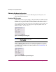
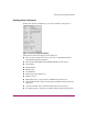


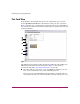
Table Of Contents
- Contents
- About this Guide
- Overview
- Feature Keys
- Managing the Director
- Element Manager Description
- Using the Element Manager
- Backing Up and Restoring Element Manager Data
- Monitoring and managing the Director
- Hardware View
- Port Card View
- Port List View
- Node List View
- Performance View
- FRU List View
- Port Operational States
- Link Incident Alerts
- Threshold Alerts
- Configuring the Director
- Configuring Identification
- Configuring Management Style
- Configuring Operating Parameters
- Configuring a Preferred Path
- Configuring Switch Binding
- Configuring Ports
- Configuring Port Addresses (FICON Management Style)
- Configuring an SNMP Agent
- Configuring Open Systems Management Server
- Configuring FICON Management Server
- Configuring Feature Key
- Configuring Date and Time
- Configuring Threshold Alerts
- Creating New Alerts
- Figure 49: Configure Threshold Alert(s) dialog box
- Figure 50: New Threshold Alerts dialog box - first screen
- Figure 51: New Threshold Alerts dialog box - second screen
- Figure 52: New Threshold Alerts dialog box - third screen
- Figure 53: New Threshold Alerts dialog box - summary screen
- Figure 54: Configure Threshold Alerts dialog box - alert activated
- Modifying Alerts
- Activating or Deactivating Alerts
- Deleting Alerts
- Creating New Alerts
- Configuring Open Trunking
- Exporting the Configuration Report
- Enabling Embedded Web Server
- Enabling Telnet
- Backing Up and Restoring Configuration Data
- Using Logs
- Using Maintenance Features
- Optional Features
- Information and Error Messages
- Index
Monitoring and managing the Director
78 Director Element Manager User Guide
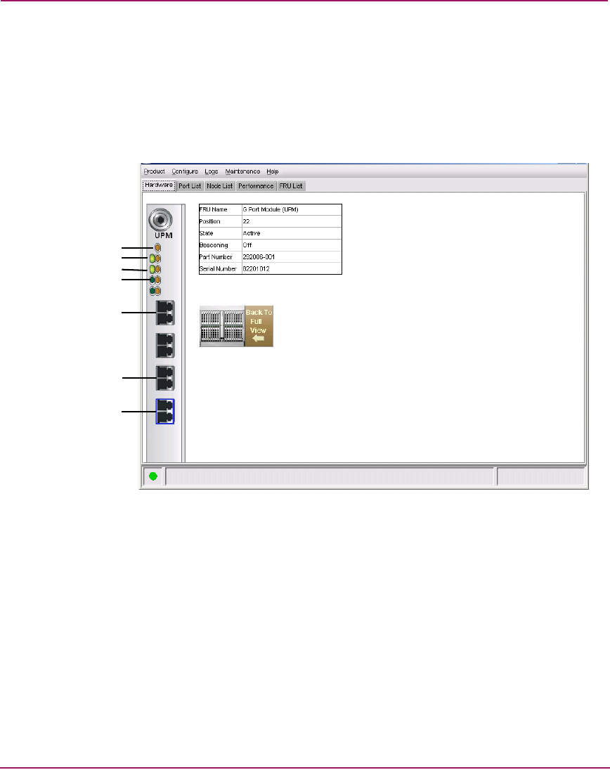
Port Card View
In the Hardware View, double-click a port card or right-click a port card and
choose Open Port Card View for a detailed view of the port card, as shown in
Figure 22. In this view, colored indicators reflect functions of the actual LEDs on
the card. The table in the Port Card View displays the port operating state and vital
product information.
Figure 22: Port Card View
The numbered paragraphs that follow describe the numbered status symbols and
LED indicators shown on the Port Card View in Figure 22. Port states are
described in detail under “Port Operational States” on page 109.
1 The amber indicator at the top of a port card illuminates when the port card
fails. A port card fails when one or more individual ports fail.
Four sets of green and amber LEDs beneath the amber card status indicator
correspond to the four port connectors installed vertically down the port card.
2
4
5
6
1
7
3