Intrepid® 6064 Director Installation and Service Manual P/N 620-000108-920 REV A 380 Interlocken Crescent Broomfield, CO 80021-3464 Corporate Headquarters: 800-545-5773 Sales E-mail: sales@mcdata.com Web: www.mcdata.
Record of Revisions and Updates ii Revision Date Description 620-000108-100 2/2001 Initial release of the manual 620-000108-200 5/2001 Updates to describe Release 4.1 of the Enterprise Fabric Connectivity Manager application. 620-000108-300 6/2001 Additional updates to describe Release 4.1 of the Enterprise Fabric Connectivity Manager application. 620-000108-400 11/2001 Updates to describe Release 4.2 of the Enterprise Fabric Connectivity Manager application.
Copyright © 2000-2005 McDATA Corporation. All rights reserved. Printed January 2005 Eleventh Edition No part of this publication may be reproduced or distributed in any form or by any means, or stored in a database or retrieval system, without the prior written consent of McDATA Corporation. The information contained in this document is subject to change without notice. McDATA Corporation assumes no responsibility for any errors that may appear.
iv Intrepid® 6064 Director Installation and Service Manual
Contents Preface ........................................................................................................................ xxiii Chapter 1 General Information Director Description .........................................................................1-1 Field-Replaceable Units ...................................................................1-4 Cable Management Assembly .................................................1-5 Front Bezel ....................................................
Contents Task 1: Verify Installation Requirements .......................................2-8 Task 2: Install the Ethernet Hub......................................................2-9 Task 3: Install the Director .............................................................2-12 Subtask A: Unpack and Inspect the Director ......................2-12 Subtask B: Rack-Mount Installation......................................2-13 Subtask C: Turn-on Director Power......................................
Contents Subtask J: Configure Threshold Alerts ................................ 2-67 Subtask K: Configure OpenTrunking .................................. 2-71 Subtask L: Enable SANpilot Interface and Telnet Access . 2-73 Subtask M: Configure, Enable, and Test E-mail Notification... 2-73 Subtask N: Configure and Enable Ethernet Events ........... 2-75 Subtask O: Configure, Enable, and Test Call-Home Notification ............................................................................................
Contents Factory Defaults.........................................................................3-2 Quick Start ..................................................................................3-2 MAP 0000: Start MAP ......................................................................3-9 MAP 0100: Power Distribution Analysis ....................................3-34 MAP 0200: POST Failure Analysis ...............................................3-44 MAP 0300: Server Application Problem Determination....
Contents Block a Port Card (Management Server) ............................. 4-47 Unblock a Port (Management Server) ............................................................. 4-48 Unblock a Port Card (Management Server)........................ 4-49 Block a Port (SANpilot Interface) ......................................... 4-49 Unblock a Port (SANpilot Interface) .................................... 4-50 Cleaning Fiber-Optic Components..............................................
Contents Chapter 6 Illustrated Parts Breakdown Front-Accessible FRUs .....................................................................6-2 Rear-Accessible FRUs.......................................................................6-4 Miscellaneous Parts ..........................................................................6-5 Power Cords and Receptacles.........................................................6-6 Appendix A Messages Intrepid 6064 Element Manager Messages ..........................
Contents Management Server Description .................................................. D-1 Management Server Specifications ....................................... D-2 Ethernet Hub Description .............................................................. D-2 Appendix E Restore Management Server Requirements ...................................................................................E-1 Restore Management Server Procedure .......................................
Contents xii Intrepid® 6064 Director Installation and Service Manual
Figures 1-1 1-2 1-3 1-4 1-5 1-6 1-7 1-8 1-9 1-10 1-11 1-12 Cabinet-Mounted Intrepid 6064 Directors and Management Server ... 1-3 Director FRUs (Front Access) ..................................................................... 1-4 Director FRUs (Rear Access) ....................................................................... 1-5 UPM Card LEDs and Connectors .............................................................. 1-8 XPM Card LEDs and Connectors .................................................
Figures 2-17 2-18 2-19 2-20 2-21 2-22 2-23 2-24 2-25 2-26 2-27 2-28 2-29 2-30 2-31 2-32 2-33 2-34 2-35 2-36 2-37 2-38 2-39 2-40 2-41 2-42 2-43 2-44 2-45 2-46 2-47 2-48 2-49 2-50 2-51 2-52 2-53 2-54 2-55 2-56 2-57 2-58 xiv EFCM Log In or SANavigator Log In Dialog Box .................................. 2-27 Control Panel Window ............................................................................... 2-28 Identification Changes Dialog Box ...........................................................
Figures 2-59 2-60 2-61 2-62 2-63 2-64 2-65 2-66 2-67 2-68 2-69 2-70 2-71 2-72 2-73 2-74 2-75 2-76 2-77 2-78 2-79 2-80 2-81 2-82 2-83 2-84 2-85 2-86 2-87 Email Event Notification Setup Dialog Box ............................................ 2-74 Configure Ethernet Events Dialog Box ................................................... 2-75 Configure Call Home Event Notification Dialog Box ........................... 2-76 InCD Icon (Unformatted CD) .............................................................
Figures xvi 3-14 3-15 3-16 3-17 3-18 3-19 3-20 3-21 3-22 3-23 3-24 3-25 3-26 3-27 3-28 3-29 3-30 3-31 3-32 3-33 3-34 3-35 3-36 3-37 3-38 3-39 3-40 3-41 3-42 3-43 3-44 3-45 3-46 3-47 3-48 3-49 3-50 Windows Task Manager Dialog Box (Applications Page) .................... 3-50 Shut Down Windows Dialog Box ............................................................. 3-51 LCD Panel During Boot Sequence ............................................................ 3-51 Dr. Watson for Windows 2000 Dialog Box ..
Figures 4-6 4-7 4-8 4-9 4-10 4-11 4-12 4-13 4-14 4-15 4-16 4-17 4-18 4-19 4-20 4-21 4-22 4-23 4-24 4-25 4-26 4-27 4-28 4-29 4-30 4-31 4-32 4-33 4-34 4-35 4-36 4-37 4-38 4-39 4-40 4-41 4-42 4-43 4-44 4-45 4-46 4-47 4-48 Intrepid 6064 Threshold Alert Log .......................................................... Intrepid 6064 Open Trunking Log ........................................................... SANpilot Monitor Panel (Logs Page) ...................................................... Port List View .
Figures xviii 4-49 4-50 4-51 4-52 4-53 4-54 4-55 4-56 4-57 4-58 4-59 4-60 4-61 4-62 4-63 4-64 4-65 4-66 4-67 4-68 4-69 4-70 4-71 4-72 4-73 4-74 4-75 4-76 4-77 4-78 4-79 4-80 4-81 4-82 McDATA File Center Home Page ............................................................ 4-68 McDATA File Center (Login Page) .......................................................... 4-68 McDATA File Center (Find Documents Page) ....................................... 4-69 McDATA File Center (Documents Match Page) ......
Figures 5-9 5-10 5-11 5-12 5-13 5-14 5-15 5-16 5-17 5-18 5-19 Power Supply Removal and Replacement ............................................. RFI Shield Removal and Replacement .................................................... SBAR Assembly Removal and Replacement .......................................... Fan Module Removal and Replacement ................................................. Power Module Assembly Removal and Replacement .......................... Backplane Removal and Replacement ....
Figures xx Intrepid® 6064 Director Installation and Service Manual
Tables 1-1 Element Manager Alert Symbols, Messages, and Status ...................... 1-15 2-1 2-2 2-3 2-4 2-5 2-6 Factory-Set Defaults (Intrepid 6064 Director) .......................................... 2-1 Factory-Set Defaults (Management Server) .............................................. 2-2 Installation Task Summary ......................................................................... 2-4 Factory-Set Defaults (Intrepid 6064 Director) ........................................
Tables xxii 4-2 Port Operational States ............................................................................... 4-13 5-1 5-2 5-3 Factory-Set Defaults ...................................................................................... 5-1 Concurrent FRUs ........................................................................................... 5-4 Nonconcurrent FRUs ....................................................................................
Preface This publication is part of a documentation suite that supports the McDATA® Intrepid® 6064 Director. Who Should Use This Manual This publication is intended for installation and service representatives experienced with the director, storage area network (SAN) technology, and Fibre Channel technology. Organization of This Manual This publication includes six chapters and four appendices organized as follows: Chapter 1, General Information.
Preface data, collect maintenance data, power-on, power-off, and reset the director, set the director online or offline, block ports, manage director firmware, clean fiber optics, and install or upgrade management server software. Chapter 5, Removal and Replacement Procedures (RRPs). This chapter describes procedures to remove and replace director FRUs. Chapter 6, Illustrated Parts Breakdown. This chapter illustrates, describes, and shows the location of director FRUs.
Preface Related Publications Ordering Printed Manuals Where to Get Help Other publications that provide additional information about the director include: • McDATA Products in a SAN Environment Planning Manual (620-000124). • McDATA Intrepid 6140 and 6064 Directors Element Manager User Manual (620-000153). • McDATA Enterprise Fabric Connectivity Manager User Manual (620-005001). • McDATA SANpilot User Manual (620-000160). • McDATA SNMP Support Manual (620-000131).
Preface For technical support for the SANavigator® application, contact the SANavigator Solution Center at the phone number or e-mail address listed below. Phone: (877) 948-4448 E-mail: support@sanavigator.com Forwarding Publication Comments We welcome comments about this publication. Please send comments to the McDATA Solution Center by telephone, fax, or e-mail. The numbers and e-mail address are listed above. Please identify the manual, page numbers, and details.
Preface Federal Communications Commission (FCC) Statement The director generates, uses, and can radiate radio frequency energy, and if not installed and used in accordance with the instructions provided, may cause interference to radio communications. The directors have been tested and found to comply with the limits for Class A computing devices pursuant to Subpart J of Part 15 of the FCC Rules, which are designed to provide reasonable protection against such interference in a commercial environment.
Preface • The director conforms with all protection requirements of EU directive 73/23/EEC (Low Voltage Directive) in accordance with of the laws of the member countries relating to electrical safety. • The director conforms with all protection requirements of EU directive 93/68/EEC (Machinery Directive) in accordance with of the laws of the member countries relating to safe electrical and mechanical operation of the equipment.
Preface General Precautions ESD Precautions When installing or servicing the director, follow these practices: • Always use correct tools. • Always use correct replacement parts. • Keep all paperwork up to date, complete, and accurate. The director contains electrostatic discharge (ESD) sensitive FRUs. When working with any director FRU, always use correct ESD procedures. • Always wear a wrist grounding strap connected to chassis ground (if the director is plugged in) or a bench ground.
Preface xxx Intrepid® 6064 Director Installation and Service Manual
1 General Information The McDATA® Intrepid™ 6064 Director provides up to 64 ports of high-performance, dynamic Fibre Channel connectivity for switched fabric devices in a storage area network (SAN). The director provides a scalable bandwidth (1, 2, or 10 gigabits per second), redundant switched data paths, and long transmission distances. This chapter presents information and features of the director and its management, including: • Director description. • Field-replaceable units (FRUs).
General Information 1 computing environments, and provides data transmission and flow control between device node ports (N_Ports) as dictated by the Fibre Channel Physical and Signaling Interface (FC-PH 4.3). Through interswitch links (ISLs), the director can also connect to one or more additional directors to form a Fibre Channel multiswitch fabric.
General Information 1 Figure 1-1 Cabinet-Mounted Intrepid 6064 Directors and Management Server Director Description 1-3
General Information 1 Field-Replaceable Units The director provides a modular design that enables quick removal and replacement of FRUs. This section describes director FRUs and controls, connectors, and indicators associated with the FRUs. Director FRUs accessed from the front (Figure 1-2) include the: Figure 1-2 • Cable management assembly. • Front bezel. • Control processor (CTP) cards. • Universal port module (UPM) cards (1 and 2 Gbps). • 10 Gbps port module (XPM) cards. • Power supplies.
General Information 1 Figure 1-3 Director FRUs (Rear Access) Cable Management Assembly The cable management assembly at the bottom front of the director provides routing for Ethernet cables attached to CTP2 cards and fiber-optic cables attached to director ports. The assembly rotates up to provide front access to the redundant power supplies. Front Bezel The bezel at the top front of the director includes an amber system error light-emitting diode (LED) and a green power LED.
General Information 1 The CTP2 card provides an initial machine load (IML) button and a RESET button (recessed) on the faceplate. When the IML button is pressed, held for three seconds, and released, the director performs an IML that reloads the firmware from FLASH memory. This operation is not disruptive to Fibre Channel traffic. When the RESET button is pressed and held for three seconds, the director performs a reset.
General Information 1 Each card faceplate contains a green LED that illuminates if the card is operational and active, and an amber LED that illuminates if the card fails. Both LEDs are extinguished on an operational backup card. The amber LED blinks if FRU beaconing is enabled. UPM Card Each UPM card (Figure 1-4) provides four full-duplex generic ports (G_Ports) that transmit or receive data at 1 or 2 gigabits per second (Gbps). G_Port functionality depends on the type of cable attachment.
General Information 1 Figure 1-4 XPM Card 1-8 UPM Card LEDs and Connectors Each XPM card (Figure 1-5) provides one full-duplex generic port (G_Port) that transmits or receives data at 10 Gbps. The card faceplate contains: • One duplex LC connector for attaching fiber-optic cables. • Amber and green LEDs that indicate port status similar to the LEDs on the UPM cards (UPM Card on page 1-7).
General Information 1 Figure 1-5 XPM Card LEDs and Connectors SFP and XFP Transceivers Singlemode or multimode fiber-optic cables attach to director ports through 1 or 2 Gbps small form-factor pluggable (SFP, Figure 1-6 - for UPM cards) or 10 Gbps form-factor pluggable (XFP, Figure 1-7 - for XPM cards) optic transceivers. The fiber-optic transceivers provide duplex LC® connectors and can be detached from director ports for easy replacement. NOTE: SFP and XFP transceivers are not interchangeable.
General Information 1 Power Supply 1-10 Figure 1-6 Small Form-Factor Pluggable (SFP) transceiver Figure 1-7 Ten Gbps Form-Factor Pluggable (XFP) Transceiver Redundant, load-sharing power supplies step down and rectify facility input power to provide 48-volt direct current (VDC) power to director FRUs. The power supplies also provide overvoltage and overcurrent protection. Either power supply can be replaced while the director is powered on and operational.
General Information 1 Each power supply has a separate backplane connection to allow for different AC power sources. The power supplies are input rated at 85 to 264 volts alternating current (VAC). The faceplate of each power supply provides the following status LEDs: • A green PWR OK LED illuminates if the power supply is operational and receiving AC power. • An amber FAULT LED illuminates if the power supply fails.
General Information 1 Fan Module Two fan modules, each containing three fans (six fans total), provide cooling for director FRUs, as well as redundancy for continued operation if a fan fails. A fan module can be replaced while the director is powered on and operating, provided the module is replaced within ten minutes (after which software powers off the director). An amber LED for each fan module illuminates if one or more fans fail or rotate at insufficient angular velocity.
General Information 1 Error-Detection, Reporting, and Serviceability Features The director provides the following error detection, reporting, and serviceability features: • Light-emitting diodes (LEDs) on director FRUs and the front bezel that provide visual indicators of hardware status or malfunctions. • Redundant FRUs (logic cards, power supplies, and cooling fans) that are removed or replaced without disrupting director or Fibre Channel link operation.
General Information 1 required) LED on the FRU flashes. When unit beaconing is enabled, the system error indicator on the front bezel flashes. Beaconing does not affect port, FRU, or director operation. • An internal modem for use by support personnel to dial-in to the management server for event notification and to perform remote diagnostics. • Automatic notification of significant system events (to support personnel or administrators) through e-mail messages or the call-home feature.
General Information 1 Element Manager Status Indicators In addition to the visual indicators on the director chassis, the Element Manager application presents alert symbols and messages that describe the condition of the director and its FRUs. These alert symbols, messages, and a description are summarized in Table 1-1. Table 1-1 Element Manager Alert Symbols, Messages, and Status Symbol Message Description Fully operational All components and installed ports are operational.
General Information 1 Tools Supplied with the Director The following tools are supplied with the director. Use of the tools may be required to perform installation, test, service, or verification tasks. • Torque tool with hexagonal adapter - The torque tool with 5/32” hexagonal adapter (Figure 1-8) is required to remove and replace director logic cards.
General Information 1 Figure 1-10 Loopback Plug • Figure 1-11 Fiber-Optic Protective Plug • Figure 1-12 Tools Supplied by Service Personnel Fiber-optic protective plug - For safety and port transceiver protection, fiber-optic protective plugs (Figure 1-11) must be inserted in all director ports without fiber-optic cables attached. The director is shipped with protective plugs installed in all ports.
General Information 1 • Standard flat-tip and cross-tip (Phillips) screwdrivers Screwdrivers are required to remove, replace, adjust or tighten various FRUs, chassis, or cabinet components. • T10 Torx® tool - The tool is required to rack-mount the director or to remove, replace, adjust or tighten various chassis or cabinet components. • Electrostatic discharge (ESD) grounding cable with attached wrist strap - Use of the ESD wrist strap is required when working in and around the director card cage.
General Information 1 The interface allows service personnel to perform configuration tasks, view system alerts and related log information, and monitor director status, port status, and performance. FRU status and system alert information are highly visible. • Customer-supplied PC or UNIX-based platform with the server and client SANavigator and Intrepid 6064 Element Manager applications installed. • Simple network management protocol (SNMP).
General Information 1 1-20 Intrepid® 6064 Director Installation and Service Manual
2 Installation Tasks This chapter describes tasks to install, configure, and verify operation of the Intrepid 6064 Director, management server, and SANpilot interface. The director can be mounted in a McDATA FC-512 Fabricenter equipment cabinet, in a standard 19-inch equipment rack, or on a table top. Factory Defaults Table 2-1 lists the defaults for the Intrepid 6064 Director.
Installation Tasks 2 Table 2-2 lists the defaults for the one rack unit (1U) high, rack-mount management server.
Installation Tasks 2 Installation Options NOTE: The screens in this manual may not match the screens on your server and workstation. The title bars have been removed and the fields may contain data that does not match the data seen on your system. The director is installed in one of the following configurations: • Fabricenter equipment cabinet - Up to four directors, a rack-mount management server, and an Ethernet hub are delivered (cabled and installed) in a McDATA equipment cabinet.
Installation Tasks 2 Table 2-3 Installation Task Summary Task Number and Description Required or Optional Task 1: Verify Installation Requirements. Required. 2-8 Task 2: Install the Ethernet Hub. Optional - perform this task only if the hub is required to connect the director to the management server or to the Internet (SANpilot interface). 2-9 Task 3: Install the Director. Required. 2-12 Subtask A: Unpack and Inspect the Director Required - if not installed in equipment cabinet.
Installation Tasks 2 Table 2-3 Installation Task Summary (continued) Task Number and Description Required or Optional Page Subtask A: Assign User Names and Passwords to SAN Management Application Required if the management server is installed. 2-39 Subtask B: Identify the Director to the SAN Management Application Required if the management server is installed. 2-42 Subtask C: Verify Director-to-SAN Management Application Communication Required if the management server is installed.
Installation Tasks 2 Table 2-3 Installation Task Summary (continued) Task Number and Description Subtask K: Configure OpenTrunking Required or Optional Required if the Element Manager application is installed. 2-71 Subtask L: Enable SANpilot Interface and Telnet Access Optional - configure for SANpilot interface. 2-73 Subtask M: Configure, Enable, and Test E-mail Notification 2-73 Optional - configure for e-mail notification.
Installation Tasks 2 Table 2-3 Installation Task Summary (continued) Task Number and Description Required or Optional Page Subtask L: Enable or Disable OSMS and Host Control Required if the director is managed through the SANpilot interface. 2-98 Subtask M: Change User Password Required if the director is managed through the SANpilot interface. 2-99 Subtask N: Configure Port Binding Required if the director is managed through the SANpilot interface.
Installation Tasks 2 Task 1: Verify Installation Requirements Verify the following requirements are met prior to director installation. Ensure: • A site plan is prepared, configuration planning tasks are complete, planning considerations are evaluated, and related planning checklists are complete. Refer to the McDATA Products in a SAN Environment Planning Manual (620-000124). • Fabric and device connectivity are evaluated, and the related planning worksheet is complete.
Installation Tasks 2 Task 2: Install the Ethernet Hub This task provides the instructions to unpack and inspect one or more Ethernet hubs and install the hubs on a desktop or in a rack-mount configuration. NOTE: If the hub is delivered (with the director and management server) as part of a McDATA FC-512 Fabricenter equipment cabinet, go to Task 7: Configure Director to the SAN Management Application on page 2-39. Unpack and inspect the Ethernet hub(s). 1.
Installation Tasks 2 Figure 2-1 Mounting Bracket Installation (Ethernet Hub) 2. Position the first hub in the equipment rack as directed by the customer. Align screw holes in the mounting brackets with screw holes in the rack-mount standards. NOTE: The hub is 1.75 inches, or one rack unit (1U) high. 3. Secure both sides of the hub to the rack-mount standards (Figure 2-2). Use the 1/8-inch Allen wrench and four Allen-head mounting screws (10/32 x 0.5-inch) provided.
Installation Tasks 2 5. To daisy-chain (connect) the hubs: a. To connect the top and middle hubs in the stack, connect an RJ-45 patch cable to port 24 of the top hub, then connect the cable to port 12 of the middle hub. b. To connect the bottom and middle hubs in the stack, connect a second RJ-45 patch cable to port 24 of the middle hub, then connect the cable to port 12 of the bottom hub. c.
Installation Tasks 2 NOTE: Ensure each hub is connected to a separate rack power strip. 7. Inspect the front panel of each hub. Ensure each green Power LED illuminates. Task 3: Install the Director CAUTION Use safe lifting practices when moving the product. This task provides instructions to unpack the director, install the director in a rack-mount configuration, and perform initial configuration functions.
Installation Tasks 2 Subtask B: Rack-Mount Installation CAUTION Use safe lifting practices when moving the product. Perform the following steps to install the director in a customersupplied equipment rack. A #2 Phillips screwdriver is required. 1. Locate the rack-mount position as directed by the customer. The director is 15.75 inches (9U) high. 2. Verify all FRUs, including the SFP and XFP optical transceivers, logic cards, fans, and power supplies are installed as ordered. 3.
Installation Tasks 2 Figure 2-4 AC Power Connections (Director) 3. Connect the equipment rack power cords to separate (for redundancy) facility power sources that provide single-phase, 120 to 240 VAC voltage. 4. Power on the rack power strips. 5. Inspect the front panel of each rack-mounted Ethernet hub. Ensure each green Power LED illuminates. 6. At the bottom rear of the director, set the power switch (circuit breaker) to the up position. The director powers on and performs POSTs.
Installation Tasks 2 Task 4: Configure Director Network Information The director is delivered with the following default network addresses (Table 2-4): Table 2-4 Factory-Set Defaults (Intrepid 6064 Director) Item Default Customer-level password (maintenance port access) password Maintenance-level password (maintenance port access) level-2 SANpilot interface user name (case sensitive) Administrator SANpilot interface password (case sensitive) password IP address 10.1.1.10 Subnet mask 255.0.
Installation Tasks 2 2. Connect the other cable end to a 9-pin communication port (COM1 or COM2) at the rear of the maintenance terminal PC. 3. Power on the maintenance terminal. After the PC powers on, the Windows desktop displays. If required, refer to operating instructions shipped with the PC. 4. At the Windows desktop, click Start at the left side of the task bar. The Windows Workstation menu displays.
Installation Tasks 2 Figure 2-6 COMn Properties Dialog Box 8. Configure the Port Settings parameters. — Bits per second - 57600. — Data bits - 8. — Parity - None. — Stop bits - 1. — Flow control - Hardware or None. When the parameters are set, click OK. The Intrepid 6064 HyperTerminal dialog box displays. 9. At the > prompt, type the user-level password (the default is password) and press Enter. The password is case sensitive.
Installation Tasks 2 — Auto Negotiate. — Speed. — Duplex. Only the IP Address, Subnet Mask, and Gateway Address fields are configurable. Figure 2-7 HyperTerminal Dialog Box 11. Change the IP address, subnet mask, and gateway address as directed by the customer network administrator. To change director network addresses, type the following at the C> prompt and press Enter. ipconfig xxx.xxx.xxx.xxx yyy.yyy.yyy.yyy zzz.zzz.zzz.zzz Where: — The IP address is xxx.xxx.xxx.xxx — The subnet mask is yyy.yyy.yyy.
Installation Tasks 2 14. Click Yes. A second HyperTerminal message box appears (Figure 2-8). Figure 2-8 HyperTerminal Dialog Box 15. Click No to exit and close the HyperTerminal application. 16. Power off the maintenance terminal: 17. Disconnect the RS-232 null modem cable from the director and the maintenance terminal. Replace the protective cap over the maintenance port. 18. IML the director (IML the Director (CTP Front Panel) on page 4-54).
Installation Tasks 2 Task 5: Install the Management Server The management server is a 1U high, rack-mount unit with the SAN management (SANavigator or EFCM) and Intrepid 6064 Element Manager applications installed. This task provides instructions to unpack, install, and configure the management server. Unpack, inspect, and install the management server. 1. Inspect the shipping container for damage caused during transit.
Installation Tasks 2 Figure 2-9 Management Server Connections b. Connect the remaining end of the Ethernet cable to the LAN. — If the server is installed on a customer-supplied LAN segment, connect the cable to the LAN as directed by the customer network administrator. — If the server is installed on the McDATA-qualified Ethernet hub, connect the cable to any available hub port. 7. If required, connect the management server to the customer corporate intranet (public LAN interface).
Installation Tasks 2 — The green liquid crystal display (LCD) panel illuminates. — The green hard disk drive (HDD) LED blinks momentarily, and processor speed and random-access memory information display momentarily at the LCD panel. — The server performs the boot sequence from the basic input/output system (BIOS). During the boot sequence, the server performs additional POSTs and displays the following information at the LCD panel: • Host name. • System date and time. • LAN 1 and LAN 2 IP addresses.
Installation Tasks 2 Task 6: Configure the Management Server Subtask A: Configure Password and Network Addresses Verify the type of LAN installation with the customer network administrator. • If the management server or Fabricenter equipment cabinet is installed on a dedicated LAN, network information does not require change. Change the default password for the server LCD panel (if required by the customer), then go to Subtask B: Configure Management Server Information on page 2-25.
Installation Tasks 2 4. Use the arrow keys to input a new 4-digit numeric password and press ENTER. The Save Change panel appears. 5. Press ENTER. The panel returns to the LAN 1 Setting?? message and the password changes. Configure Private LAN Addresses To configure TCP/IP network information for the private LAN connection (LAN 2): 1. At the management server LCD panel, press ENTER. The Welcome!! or operational information message changes to the Input Password panel. 2.
Installation Tasks 2 Configure Public LAN Addresses To configure TCP/IP network information for the public LAN connection (LAN 1): 1. At the management server LCD panel, press ENTER. The Welcome!! or operational information message changes to the Input Password panel. 2. Use the arrow keys to input the default or changed password and press ENTER. The LAN 1 Setting?? message appears. 3. Press ENTER and the following message appears (Figure 2-13). Input IP: 192.168.000.
Installation Tasks 2 If required, change the management server gateway addresses and domain name system (DNS) server IP addresses to conform to the customer LAN addressing plan. The gateway addresses are the addresses of the local router for the corporate intranet. Access the Management Server Desktop To login and access the management server desktop: 1. Ensure the management server and a PC are connected through an Ethernet LAN segment.
Installation Tasks 2 NOTE: Do not simultaneously press Ctrl, Alt, and Delete. This action logs the user on to the PC, not the management server. Figure 2-16 Log On to Windows Dialog Box 5. Type the default Windows 2000 user name and password and click OK. The management server Windows 2000 desktop opens and the EFCM Log In or SANavigator Log In dialog box displays (Figure 2-17). NOTE: The default Windows 2000 user name is Administrator and the default password is password.
Installation Tasks 2 Configure Management Server Names To configure the management server name and workgroup name: 1. At the Windows 2000 desktop, click Start at the left side of the task bar (bottom of the desktop), then select Settings, then Control Panel. The Control Panel window displays (Figure 2-18). Figure 2-18 Control Panel Window 2. Click the Network Identification tab. The System Properties dialog box displays with the Network Identification tab selected. 3. Click Properties.
Installation Tasks 2 Figure 2-19 Identification Changes Dialog Box 4. At the Computer Name field, change the name to MGMTSERVER, at the Workgroup field, change the name to WORKGROUP, then click OK. The dialog box closes. 5. Record the computer and workgroup names. 6. At the System Properties dialog box, click OK to close the dialog box and return to the Control Panel window. 7. Click close (X) at the upper right corner of the Control Panel window to return to the Windows 2000 desktop.
Installation Tasks 2 4. Click Properties. The Local Area Connection 2 Properties dialog box displays. 5. Double-click the Internet Protocol (TCP/IP) entry. The Internet Protocol (TCP/IP) Properties dialog box displays (Figure 2-20). Figure 2-20 Internet Protocol (TCP/IP) Properties Dialog Box 6.
Installation Tasks 2 a. At the Windows 2000 desktop, click Start at the left side of the task bar (bottom of the desktop), then select Shut down. The Shut Down Windows dialog box appears. b. At the Shut Down Windows dialog box, select the Restart option and click OK to reboot the server. c. Perform Access the Management Server Desktop on page 2-26. Subtask C: Configure Windows 2000 Users Configure password access for all authorized Windows 2000 users of the management server.
Installation Tasks 2 Change Default Administrator Password To change the administrator password from the default (password) to a customer-specified password: 1. Click the Send Ctrl-Alt-Del button at the top of the window surrounding the Users and Passwords dialog box. The Windows Security dialog box displays (Figure 2-22). NOTE: Do not simultaneously press Ctrl, Alt, and Delete. This action controls the PC, not the rack-mount management server. Figure 2-22 Windows Security Dialog Box 2.
Installation Tasks 2 3. At the Old Password field, type the old password. At the New Password and Confirm New Password fields, type the new password. NOTE: The New Password and Confirm New Password fields are case-sensitive. 4. Click OK. The default administrator password changes and the Change Password dialog box closes. 5. Click Cancel at the Windows Security dialog box to return to the Users and Passwords dialog box. Add a New User To set up a new Windows 2000 user: 1.
Installation Tasks 2 Figure 2-25 Add New User Wizard (Second Window) 3. Type the new user password in the Password and Confirm password fields, then click Next. The third window of the Add New User wizard displays (Figure 2-26). Figure 2-26 Add New User Wizard (Third Window) 4. Based on the level of access to be granted, select the Standard user, Restricted user, or Other radio button. If the Other radio button is selected, choose the type of access from the adjacent list box. 5. Click Finish.
Installation Tasks 2 Change User Properties To change user properties: 1. At the Users and Passwords dialog box, highlight the user (srvacc, for example) at the Users for this computer field and click Properties. The MGMTSERVER\srvacc Properties dialog box displays with the General tab selected (Figure 2-27). Figure 2-27 MGMTSERVER\srvacc Properties Dialog Box (General Tab) 2. Type the new user information in the User name, Full name, and Description fields, then click the Group Membership tab.
Installation Tasks 2 3. Based on the level of access to be changed, select the Standard user, Restricted user, or Other radio button. If the Other radio button is selected, choose the type of access from the adjacent list box. 4. Click OK. The new user information is added and the MGMTSERVER\srvacc Properties dialog box closes. Record the user information. 5. If no other users are to be changed, click OK to close the Users and Passwords dialog box. 6.
Installation Tasks 2 Figure 2-30 Date/Time Properties Dialog Box (Time Zone Tab) 4. To change the time zone: a. Select the time zone from the drop-down list at the top of the dialog box. b. If instructed by the customer system administrator, select the Automatically adjust clock for daylight saving changes check box. c. Click Apply. Record time zone and daylight savings information. 5. Click the Date & Time tab. The Date/Time Properties dialog box displays with the Date & Time page open. 6.
Installation Tasks 2 Subtask E: Configure the Call-Home Feature NOTE: The call-home feature may not be available if the EFC Manager application (EFCM Lite) is installed on a customer-supplied PC. NOTE: These steps are valid only for an initial installation. Several dialog boxes appearing in this procedure are configured only once per installation. To configure the call-home feature: 1.
Installation Tasks 2 Subtask F: Record or Verify Management Server Restore Information Windows 2000 configuration information must be recorded to restore the management server in case of hard drive failure. Ensure that the following management server configuration information is verified or recorded: • Network configuration information. — LCD panel password. — Network addresses (IP address, subnet mask, gateway address, and DNS server IP address) for private LAN connection (LAN 2).
Installation Tasks 2 NOTE: The default SAN management application user name is Administrator and the default password is password. The user name and password are case-sensitive. 2. Click Login. The application opens and the EFCM or SANavigator main window appears (Figure 2-32). Figure 2-32 Main Window: Example (EFCM or SANavigator) 3. Select Users from the SAN menu. The EFCM Server or SANavigator Server Users dialog box displays (Figure 2-33).
Installation Tasks 2 Figure 2-34 Add User Dialog Box 5. Enter information in fields as directed by the customer: — Name - Click in this field and type a new user name up to 16 alphanumeric characters. Control characters and spaces are not valid. The user name is case-sensitive. — Email Address - Click in this field and type one or more new user e-mail addresses. Separate multiple addresses with a semicolon. — User ID - Click in this field and type a unique user ID for the new user.
Installation Tasks 2 10. When finished, click OK at the EFCM Server or SANavigator Server Users dialog box to return to the EFCM or SANavigator main window. Subtask B: Identify the Director to the SAN Management Application To manage a new director, it must be identified to and discovered by the SAN management application. To identify the new director: 1. At the SAN management application (EFCM or SANavigator main window), select the Setup option from the Discover menu.
Installation Tasks 2 Figure 2-36 Domain Information Dialog Box (IP Address Page) 3. Type a director description in the Description field. 4. Type the director IP address in the IP Address field. 5. Type the director subnet mask in the Subnet Mask field. 6. At the Data Source for Domain area of the dialog box, select the Use auto detection, Use the server, or Use a specific RDC radio button. 7.
Installation Tasks 2 3. Select the Element Manager option from the pop-up menu. When the Element Manager application opens, the last view (tab) accessed by a user opens by default, such as the Hardware View. 4. Inspect director status at the Hardware View and perform one of the following: — If the director appears operational, go to Subtask D: Configure Feature Key on page 2-45.
Installation Tasks 2 Subtask D: Configure Feature Key Perform this task to display features that have been installed or install features that are available for the director as customer-specified options. Features are installed through a feature key that is encoded to work with the serial number of the director. A feature key is a casesensitive alphanumeric string with dashes every four characters. To configure the feature key: 1. Set the director offline (Set the Director Online or Offline on page 4-43).
Installation Tasks 2 NOTE: PFE keys are encoded to work only with the serial number of the installed director. Record the key to re-install the feature. If the director must be replaced, obtain new PFE keys from the McDATA Solution Center (800-752-4572 or support@mcdata.com). Have the serial numbers of the old and new directors, and the old PFE key number or transaction code available.
Installation Tasks 2 1. At the Hardware View, click Configure at top of the view and select Open Systems Management Server from the pop-up menu. Two submenu options display: — Enable OSMS. — Host Control Prohibited. 2. Enable or disable the open systems management server by selecting the Enable OSMS option. Check the box to enable the server. 3. Allow or prohibit host (OSI server) control by selecting the Host Control Prohibited option.
Installation Tasks 2 — Host Control Prohibited - This option allows or prohibits host (S/390 or zSeries 900) control of the director. If a check mark displays, host control is prohibited. — Active = Saved - When this option is enabled, the active configuration of logical port addresses is used when the IPL configuration file is updated. If a check mark displays, the Active = Saved option is enabled. 3. Select the country code page from the Code Page list box.
Installation Tasks 2 • Configure director date and time (Subtask A: Set Director Date and Time on page 2-50). • Identify the director to the SAN management (SANavigator or EFCM) application(Subtask B: Configure Director Identification on page 2-51). • Configure director management style (open systems or FICON) (Subtask C: Configure Director Management Style on page 2-52). • Configure director parameters (Subtask D: Configure Director Parameters on page 2-53).
Installation Tasks 2 Subtask A: Set Director Date and Time The director date and time can be set manually, or set to be periodically updated by the SAN management application (the director and application synchronize at least once daily). At the Hardware View, select Date/Time from the Configure menu. The Configure Date and Time dialog box displays (Figure 2-40). Figure 2-40 Configure Date and Time Dialog Box Set Date and Time Manually To set the director date and time manually: 1.
Installation Tasks 2 Set Director to Periodically Synchronize Date and Time To set the director to periodically synchronize date and time with the SAN management application: • At the Configure Date and Time dialog box, click the Periodic Date/Time Synchronization check box to select the option (check mark in the box). Perform one of the following: — Click Activate to enable synchronization and close the Configure Date and Time dialog box.
Installation Tasks 2 Figure 2-42 Configure Identification Dialog Box a. Type a director name in the Name field. Each director should be configured with a unique name. If the director is installed on a public LAN, the name should reflect the director Ethernet network DNS host name. For example, if the DNS host name is intrepid6064.mcdata.com, the name entered in this dialog box should be intrepid6064. b. Type a director description in the Description field. c.
Installation Tasks 2 1. Ensure the director is set offline (Set the Director Online or Offline on page 4-43). 2. At the Hardware View for the selected director, select Management Style from the Product menu. The Configure Management Style menu displays. 3. Select the management style. • Select the Open Systems radio button for (non-FICON) Fibre channel environments.
Installation Tasks 2 Figure 2-43 Configure Switch Parameters Dialog Box a. At the Preferred Domain ID field, type a value between 1 through 31. The domain ID uniquely identifies each director or switch in a fabric. NOTE: All fabric-attached directors and switches must have unique domain IDs. If the value is not unique, the E_Port connection to the director segments and the director cannot communicate with the fabric. b. Click the Insistent Domain ID check box to enable this parameter.
Installation Tasks 2 3. Click Activate to save the information and close the dialog box. 4. Set the director online (Set the Director Online or Offline on page 4-43). Subtask E: Configure Fabric Parameters Perform this procedure to configure fabric parameters, including BB_Credit, R_A_TOV, E_D_TOV, and switch priority. To configure fabric parameters: 1. Ensure the director is set offline (Set the Director Online or Offline on page 4-43). 2.
Installation Tasks 2 NOTE: All fabric-attached directors and switches must be set to the same E_D_TOV. If the value is not compatible, the E_Port connection to the director segments and the director cannot communicate with the fabric. In addition, the E_D_TOV must be less than the R_A_TOV. d. Set the director priority from the Switch Priority drop-down list. Select Principal, Never Principal, or Default (the default is Default. The switch priority value designates the fabric principal switch.
Installation Tasks 2 4. Set the director online (Set the Director Online or Offline on page 4-43). Subtask F: Configure Preferred Paths The preferred path feature allows a user to specify and configure one or more ISL data paths between multiple directors or switches in a fabric. Each participating director or switch must be configured as part of a desired path.
Installation Tasks 2 Figure 2-45 Configure Preferred Paths Dialog Box 3. Click Add. The Add Preferred Path dialog box displays (Figure 2-46). Figure 2-46 Add Preferred Path Dialog Box 4. At the Source Port field, type a value that uniquely identifies the starting port for the preferred path. 5. At the Exit Port field, type a value that uniquely identifies the exit port for the preferred path. 6.
Installation Tasks 2 Subtask G: Configure Switch Binding The switch binding (SANtegrity binding) feature specifies devices that can connect to the director ports. This provides security in SAN environments by ensuring that only an intended set of devices can communicate with the director. Background: Switch Binding Specific operating parameters and optional features must be enabled for switch binding to function.
Installation Tasks 2 • If the director is online and switch binding is not enabled, all WWNs of devices attached to the director are automatically added to the membership list. SANtegrity binding parameters have no effect on zoning configurations. However, if a device WWN is in a specific zone, but the WWN is not in the membership list, the device cannot log in to a director port and cannot connect to other devices in the zone with switch binding enabled.
Installation Tasks 2 and removed from the list to prohibit element connection. Devices are allowed to connect to any F_Port or FL_Port without restriction. • Restrict F_Ports - Select this button to restrict connections from specific devices to director F_Ports or FL_Ports. WWNs can be added to the membership list to allow device connection and removed from the list to prohibit device connection. Fabric directors and switches are allowed to connect to any E_Port without restriction.
Installation Tasks 2 When the switch binding feature is installed but not enabled, the associated membership list is empty. The list is populated with device WWNs: • When switch binding is enabled with the director online, the membership list is automatically populated with the WWNs of all devices and fabric elements connected to the director. • When switch binding is enabled with the director offline, the membership list is not automatically populated.
Installation Tasks 2 5. Perform one of the following: • To allow a director port connection to a device listed in the Node List Panel, select the WWN or nickname and click Add>>. The device WWN or nickname moves to the Switch Membership List panel. • To prohibit a director port connection to a device listed in the Switch Membership List Panel, select the WWN or nickname and click <
Installation Tasks 2 Figure 2-51 Configure Ports Dialog Box a. For each port to be configured, type a port name in the associated Name field. The port name should characterize the device to which the port is attached. b. Click a check box in the Blocked column to block or unblock a port (default is unblocked). A check mark in the box indicates a port is blocked. Blocking a port prevents the attached devices or fabric switch from communicating. c.
Installation Tasks 2 NOTE: Only 24-Port switches have a switch-wide buffer pool. The Configure Ports dialog box displays the total and available buffers at the bottom of the dialog box. When information is changed in the RX BB Credit column, this information also updates. If information is entered that exceeds the buffer pool and Activate is clicked, an error message displays. Also, ports for the 24-Port switches can be individually configured between 2-12, with a total number of port credits of 150.
Installation Tasks 2 • 2.125 Gbps operation(2 Gb/sec). • 10.625 Gbps operation(10 Gb/sec). h. Click the check box in the Port Binding column to enable or disable port binding (default is disabled). A check mark in the box indicates port binding is enabled and the port can connect only to a device with a WWN listed in the Bound WWN column. i. If port binding is enabled, type the WWN or nickname of the device attached to the port in the Bound WWN column.
Installation Tasks 2 Figure 2-52 Configure SNMP Dialog Box a. For each trap recipient to be configured, type a community name in the associated Community Name field. The community name is incorporated in SNMP trap messages to ensure against unauthorized viewing or use. b. Click the check box in the Write Authorization column to enable or disable write authorization for the trap recipient (default is disabled). A check mark in the box indicates write authorization is enabled.
Installation Tasks 2 • An attention indicator (yellow triangle) associated with a port at the Hardware View. • An attention indicator (yellow triangle) in the Alert column at the Port List View. • An attention indicator (yellow triangle) in the Threshold Alerts field at the Port Properties dialog box. • Data recorded in the Threshold Alert Log. To configure threshold alerts: 1. At the Hardware View for the selected director, select Threshold Alerts from the Configure menu.
Installation Tasks 2 4. Select one of the following from the drop-down list under the Threshold Type field: • Rx Throughput - An alert occurs if the threshold value for receive throughput is reached or exceeded. • Tx Throughput - An alert occurs if the threshold value for transmit throughput is reached or exceeded. • Rx or Tx Throughput - An alert occurs if the threshold value for either receive or transmit throughput is reached or exceeded. 5. Click Next.
Installation Tasks 2 Figure 2-56 New Threshold Alerts Dialog Box (Screen 3) 10. Select the Port Type or Port List radio button. • Select Port Type radio button, then the E_Ports or F_Ports radio button to cause an alert to generate for all ports configured as either E_Ports or F_Ports. • Select Port List to configure individual ports by clicking the check box adjacent to each port number. Select Set All Ports to place a check mark adjacent to all port numbers.
Installation Tasks 2 12. Click Finish. The Configure Threshold Alerts dialog box (Figure 2-53) appears listing the name, type, and state of the configured alert. 13. To activate the alert, highlight (select) the alert and click Activate. Subtask K: Configure OpenTrunking Perform this procedure to configure the OpenTrunking parameters. 1. Ensure the OpenTrunking feature is installed and configured (Subtask D: Configure Feature Key on page 2-45). 2.
Installation Tasks 2 • To disable OpenTrunking, click the Enable OpenTrunking check box to remove the check mark, then click Activate to enable the change and close the dialog box. 5. For each director port: a. Click the check box in the Use Algorithmic Threshold column. A check mark appears in the box and a calculated default value appears (1% to 99%) in the associated field in the Threshold % column. If the default is enabled, a value cannot be entered in the Threshold % column. b.
Installation Tasks 2 — Click the Default Threshold check box. A check mark appears in the box and a calculated default value appears (1% to 99%) in the adjacent field. If the default value is enabled, a value cannot be entered in the field. — Ensure the Default Threshold check box is blank. At the adjacent field, type a percentage value from 1% to 99%. NOTE: The default low BB_Credit threshold is calculated by the director firmware. 9. Click Activate to enable the changes and close the dialog box.
Installation Tasks 2 2. At the EFCM or SANavigator main window, select the Event Notification and Email options from the Monitor menu. The Email Event Notification Setup dialog box displays (Figure 2-59). Figure 2-59 Email Event Notification Setup Dialog Box 3. To enable e-mail transmission to configured addresses, click the Enable Email Event Notification check box. NOTE: The enable function must also be activated for each director or switch through the Intrepid 6064 Element Manager application.
Installation Tasks 2 Manager User Manual (620-000153), McDATA Enterprise Fabric Connectivity Manager User Manual (620-005001), or SANavigator User Guide (621-000013). 10. Click OK to close the EFCM Server or SANavigator Users dialog box. 11. Click Test Email. A test message is sent to configured e-mail recipients. 12. Click OK to save the information and close the Email Event Notification Setup dialog box. 13. Maximize the Hardware View (Element Manager application). 14.
Installation Tasks 2 Subtask O: Configure, Enable, and Test Call-Home Notification NOTE: The call-home feature may not be available if the EFC Manager application (EFCM Lite) is installed on a customer-supplied PC. Telephone numbers and other information for the call-home feature are configured through the Windows 2000 dial-up networking application. See Subtask E: Configure the Call-Home Feature on page 2-38 for configuration instructions. 1.
Installation Tasks 2 Task 9: Configure SANtegrity Authentication (Optional) This feature is accessed from the SANtegrity Authentication Dialog box in the individual element managers applications. The element manager lets you manage one device at a time. Access the SANtegrity Authentication dialog box by clicking the Configure Menu on the element manager window and clicking SANtegrity Authentication. To access the SANtegrity Authentication, one user must have the security administrator privilege.
Installation Tasks 2 • Device tab allows the security administrator to set device to device authentication parameters. Device tab is PFE key enabled. If a proper PFE key is not provided, the Devices tab is not accessible. • IP Access Control List tab allows the security administrator to setup IP addresses that can manage the switch.
Installation Tasks 2 Figure 2-62 InCD Icon (Unformatted CD) b. Right-click the icon and select Format (F). The InCD wizard window displays. c. Click Next. Use the defaults at each window, and click Next, then Finish, to complete the CD formatting. d. When the CD is formatted, the red down arrow associated with the InCD icon changes to a green up arrow. 2. Back up the director configuration file to the management server (Managing Configuration Data on page 4-75). 3.
Installation Tasks 2 NOTE: The default TightVNC viewer password is password. e. Click the Send Ctrl-Alt-Del button at the top of the window to log on to the management server desktop. The Log On to Windows dialog box displays (Figure 2-16). NOTE: Do not simultaneously press Ctrl, Alt, and Delete. This action logs the user on to the PC, not the rack-mount management server. f. Type the default Windows 2000 user name and password and click OK.
Installation Tasks 2 • Open the SANpilot interace (Subtask B: Open the SANpilot Interface on page 2-82 • Configure ports (Subtask C: Configure Director Ports on page 2-84). • Configure BB Credit (Subtask D: Configure BB Credit on page 2-85). • Configure director identification (Subtask E: Configure Director Identification on page 2-86). • Configure director date and time (Subtask F: Configure Date and Time on page 2-88).
Installation Tasks 2 NOTE: In addition to these tasks, there are other tasks which are documented in the SANpilot User Manual and include: Configuring RADIUS Servers, Configuring IP Access Control List, and Configuring Preferred Path. These are advanced topics which are not convered in this document. Subtask A: Connect Director to Internet or Ethernet LAN Segment A PC platform with Internet access and standard web browser running Netscape Navigator® 4.6 or higher or Microsoft Internet Explorer 4.
Installation Tasks 2 Figure 2-63 Enter Network Password Dialog Box 4. Type the default user name and password. NOTE: The default SANpilot interface user name is Administrator and the default password is password. The user name and password are case-sensitive. 5. Click OK. The SANpilot interface opens with the View panel open and the Director page displayed (Figure 2-64).
Installation Tasks 2 Subtask C: Configure Director Ports Perform procedures in this section to configure names and operating characteristics for Fibre Channel ports. To configure one or more director ports: 1. At the View panel, select the Configure option at the left side of the panel. The Configure panel opens with the Ports page displayed (Figure 2-65). Use the vertical scroll bar to display additional port information rows. Figure 2-65 Configure Panel (Ports Page with Basic Info tab) a.
Installation Tasks 2 • Generic port (G_Port). • Fabric port (F_Port). • Expansion port (E_Port). e. Select from the drop-down list in the Speed column to configure the port transmission rate. Available selections are: • Auto-negotiate between 1.0625, 2.125, and 10.625 Gbps operation (Negotiate). This is the default. • 1.0625 Gbps operation (1 Gb/sec). • 2.125 Gbps operation(2 Gb/sec). • 10.625 Gbps operation(10 Gb/sec). 2. Click Activate to save and activate the changes.
Installation Tasks 2 Figure 2-66 Configure BB Credits Subtask E: Configure Director Identification Perform this procedure to configure the director name, description, location, and contact person. The Name, Location, and Contact variables configured correspond respectively to the SNMP variables sysName, sysLocation, and sysContact. These variables are used by SNMP management workstations when obtaining data from managed directors. To configure the director identification: 1.
Installation Tasks 2 Figure 2-67 Configure Panel (Director Page with Identification Tab) a. Type a director name in the Name field. Each director or switch should be configured with a unique name. The director name can be up to 24 alphanumeic characters and you can use spaces in the name. If the director is installed on a public LAN, the name should reflect the director Ethernet network domain name system (DNS) host name. For example, if the DNS host name is intrepid6064.mcdata.
Installation Tasks 2 Subtask F: Configure Date and Time Perform this procedure to configure the effective date and time for the director. To set the date and time: 1. At the Configure panel, click the Date/Time tab. The Director page displays with Date/Time selected (Figure 2-68). Figure 2-68 Configure Panel (Director Page with Date/Time Tab) a. Click the Date fields that require change, and type numbers in the following ranges: • Month (MM): 1 through 12. • Day (DD): 1 through 31.
Installation Tasks 2 2. Click Activate to save and activate the changes. The message Your changes to the date/time configuration have been successfully activated appears. Subtask G: Configure Operating Parameters Perform this procedure to configure the director preferred domain ID, insistent domain ID, rerouting delay, and domain registered state change notifications (RSCNs). To configure parameters: 1. Set the director offline. a. At the Configure panel, select Operations at the left side of the panel.
Installation Tasks 2 a. At the Preferred Domain ID field, type a value between 1 through 31. The domain ID uniquely identifies each director or switch in a fabric. NOTE: If the director is attached to a fabric element, the director and element must have unique domain IDs. If the values are not unique, the E_Port connection to the element segments and the director cannot communicate with the fabric. b. At the Insistent Domain ID field, select Enabled or Disabled.
Installation Tasks 2 5. If fabric parameters require configuration, go to Subtask H: Configure Fabric Parameters following. If the configuration is complete, set the director online. a. At the Configure panel, select the Operations option at the left side of the panel. The Operations panel opens and the Director page displays with the Beacon tab selected b. Click the Online State tab, then click Set Online. The message Your operations changes have been successfully activated appears.
Installation Tasks 2 Figure 2-70 Configure Panel (Director Page with Fabric Parameters Tab) c. At the R_A_TOV field, type a value between 10 through 1200 tenths of a second (one through 120 seconds). Ten seconds (100) is the recommended value. NOTE: If the director is attached to a fabric element, the director and element must be set to the same R_A_TOV value. If the values are not identical, the E_Port connection to the element segments and the director cannot communicate with the fabric.
Installation Tasks 2 This value designates the fabric principal switch. The principal switch is assigned a priority of 1 and controls the allocation and distribution of domain IDs for all fabric elements (including itself). Principal is the highest priority setting, Default is the next highest, and Never Principal is the lowest priority setting. The setting Never Principal means the switch is incapable of becoming a principal switch.
Installation Tasks 2 Subtask I: Configure Network Information Verify the type of LAN installation with the customer network administrator. If one director is installed on a dedicated LAN, network information (IP address, subnet mask, and gateway address) does not require change. Go to Subtask J: Configure SNMP on page 2-95. If multiple directors or switches are installed or a public LAN segment is used, network information must be changed to conform to the customer LAN addressing plan.
Installation Tasks 2 c. At the Gateway Address field, type the new value as specified by the customer network administrator (default is 0.0.0.0). 3. Click Activate to save and activate the changes. 4. Update the address resolution protocol (ARP) table for the browser PC. a. Select the Exit option from the File menu to close the SANpilot interface and browser applications. The Windows desktop displays. b. At the Windows desktop, click Start at the left side of the task bar.
Installation Tasks 2 recipient is a management workstation that receives notification (through SNMP) if a director event occurs. To configure SNMP trap recipients: 1. At the View panel, select the Configure option at the left side of the panel. The Configure panel opens with the Ports page displayed. 2. At the Configure panel, click the Management tab. The Management page displays with the SNMP tab selected (Figure 2-72). Figure 2-72 Configure Panel (Management Page with SNMP Tab) a.
Installation Tasks 2 e. Click the check box in the Write Authorization column to enable or disable write authorization for the trap recipient (default is disabled). A check mark indicates write authorization is enabled. When the feature is enabled, a management workstation user can change sysContact, sysName, and sysLocation SNMP variables. f.
Installation Tasks 2 Figure 2-73 Configure Panel (Management Page with CLI Tab) 2. Perform one of the following steps: • Click Enable to activate the CLI. The message Your changes to the CLI enable state have been successfully activated appears. • Click Disable to deactivate the CLI. The message Your changes to the CLI enable state have been successfully activated appears. 3. To enable SSH, from the Protocol drop down box, select SSH. 4. Select Activate to enable SSH for Telnet.
Installation Tasks 2 1. At the Configure panel, click the Management tab and then the OSMS tab. The Management page displays with the OSMS tab selected (Figure 2-74). Figure 2-74 Configure Panel (Management Page with OSMS Tab) 2. Select eithe Enable or Disable from the drop-down box: • Select Enable to activate the OSMS. The message Your changes to the host control enable state have been successfully activated appears. • Select Disable to deactivate the OSMS.
Installation Tasks 2 Figure 2-75 Configure Panel (Security Page with User Rights Tab) 2. Under the Currer User Records, enter the new password. 3. Click Activate to save the information. The message Your changes to the user rights configuration have been successfully activated appears. NOTE: If you want to create a user account, review the SANpilot User’s Guide for more information.
Installation Tasks 2 Figure 2-76 Configure Panel (Security Page with Port Binding Tab) a. Click the check box in the Port Binding column to enable or disable port binding for a specified port (default is disabled). b. In the Bound WWN column, type the world wide name of the device to which the port is to be bound. If port binding is enabled, only the specified device can connect to the port.
Installation Tasks 2 Switch Binding functionality enables you to identify the devices with which the switch or director can communicate. Switch Binding is available only if the SANtegrity Binding feature is installed. The Switch Binding tab view allows you to enable the product to communicate only with devices that are listed on the Switch Binding Membership List (SBML). Switch Binding restricts connections to only the devices listed on the SBML and allows no other devices to communicate with the switch.
Installation Tasks 2 Figure 2-77 Configure Panel (Security Page with Switch Binding Tab) 2. Select the connection policy from the Switch Binding State drop-down list. The switch binding state indicates the type of binding restrictions imposed on the director. Switch binding is enabled by activating Enterprise Fabric Mode (Subtask Q: Enable or Disable Enterprise Fabric Mode on page 2-107) or by enforcing a connection policy at the Switch Binding State drop-down list.
Installation Tasks 2 3. Click Submit. A confirmation dialog box appears. Click OK to close the confirmation dialog box, activate the selected connection policy, and change the switch binding state. NOTE: The Disable Switch Binding selection cannot be activated while Enterprise Fabric Mode is enabled and the director is online. 4. The Attached Nodes drop-down list contains the world wide names of attached Fibre Channel devices.
Installation Tasks 2 • If you select Detached Node WWN, type the WWN of a detached node. The WWN must be entered as hex digits, all uppercase, and with no colon seperator between digits. 4. Select the Add the following member by button next to the node that you wish to add. The tab view refreshes and the node is now listed in the SBML at the bottom of the screen. 5. If a duplicate member is submitted for the membership list, an error message is displayed that an invalid membership list has been submitted.
Installation Tasks 2 Subtask P: Configure Fabric Binding Perform this procedure to configure fabric binding by attached fabric member (domain ID and WWN). The SANtegrity feature must be installed to access this control (Subtask S: Install Feature Keys on page 2-111). If the feature is not installed, the message This Feature Not Installed appears. To configure fabric binding: 1. At the Configure panel, click the Fabric Binding tab.
Installation Tasks 2 — Activate: By selecting this button, you save the pending FBML as the active FBML and activate Fabric Binding. — Deactivate: By selecting this button, you change the Fabric Binding status from active to inactive, disabling Fabric Binding.
Installation Tasks 2 page 2-111). If the feature is not installed, the message This Feature Not Installed appears. To enable or disable EFM: 1. At the Configure panel, click the EFM tab. The Security page displays with the EFM tab selected (Figure 2-79). 2. Perform one of the following steps as required: • Click Enable to activate EFM. The message Your changes to enterprise fabric mode have been successfully activated appears. • Click Disable to deactivate EFM.
Installation Tasks 2 1. At the Configure panel, click the Performance tab. The Performance page displays with the OpenTrunking tab selected (Figure 2-80). Figure 2-80 Configure Panel (Performance Page with OpenTrunking Tab) a. At the OpenTrunking State field, select Enabled or Disabled. When this parameter is enabled, the optional OpenTrunking feature is functional. b. At the Unresolved Congestion Event Notification field, select Enabled or Disabled.
Installation Tasks 2 d. The low BB_Credit threshold is the percent time an ISL is allowed to not transmit data because BB_Credit is unavailable. When the threshold is exceeded, data is rerouted to another ISL. In addition, traffic cannot be rerouted to another lowthreshold ISL. Use one of the following to set the low BB_Credit threshold: • Click the Default check box. A check mark appears in the box and a calculated default value appears (1% to 99%) in the Low BB_Credit Threshold field.
Installation Tasks 2 Subtask S: Install Feature Keys Perform this procedure to install one or more optional features: A feature key is an alphanumeric string consisting of uppercase and lowercase characters. The number of characters may vary. The feature key is case sensitive and must be entered exactly, including dashes. The following is an example of a feature key format: XxXx-XXxX-xxXX-xX. After obtaining the feature key, install the feature.
Installation Tasks 2 Figure 2-81 Operations Panel (Feature Installation Tab) 4. Type the feature key and click Activate. The interface displays a confirmation page with a warning, stating this action overrides the current set of director features. 5. Click Activate to activate the new feature key. The director performs an IPL when the feature key is activated. NOTE: When Activate is selected, all current features are replaced with new features.
Installation Tasks 2 NOTE: If you receive the error message 238, either the feature key was entered incorrectly or the feature key is not valid for that feature. Contact the McDATA Solution Center for assistance. Task 11: Cable Fibre Channel Ports Perform this task to connect devices to the director. To cable Fibre Channel ports: 1.
Installation Tasks 2 • Configure, change, enable, or disable zone sets. A zone set is a group of zones that is activated or deactivated as a single entity across all managed products in either a single director or a multiswitch fabric. Only one zone set can be active at one time. 5. If the installation is being performed from the SANpilot interface, go to Configure Zones (SANpilot Interface) following.
Installation Tasks 2 • All names must be unique and may not differ by case only. For example, zone-1 and Zone-1 are both valid individually, but are not considered unique. • The first character of a zone set name must be a letter (A through Z or a through z). • A zone set name cannot contain spaces. • Valid characters are alphanumerics and the caret ( ^ ), hyphen ( - ), underscore ( _ ), or dollar ( $ ) symbols. • A zone set name can have a maximum of 64 characters.
Installation Tasks 2 Figure 2-83 Configure Panel (Zoning Page with Modify Zone Tab) 5. To rename a configured zone, type the new name in the Zone field and click Rename Zone. After the name is validated, the zone name is changed. 6. Add or delete zone members. • Add member by attached node WWN - Select the WWN of an attached device (node) from the Attached Node World Wide Name drop-down list and click the adjacent Add Member button. The device is added to the zone.
Installation Tasks 2 7. Changes to a zone, zoning configuration, or zone member are not saved and activated on the director until saved as part of a zone set. Go to Configure Zone Sets (SANpilot Interface) following to perform this function. Configure Zone Sets (SANpilot Interface) To configure zone sets at the SANpilot interface: 1. At the Configure panel and Zoning page, click the Zone Set tab. The Zoning page displays with the Zone Set tab selected (Figure 2-84).
Installation Tasks 2 • Enable or disable default zone - To toggle (enable or disable) the default zone state, click Enable Default Zone or Disable Default Zone. Depending on the toggle state, the Default Zone field changes to Enabled or Disabled. • Disable zone set - To disable the active zone set and place all attached devices in the default zone, click Disable Zone Set. A confirmation dialog box displays. Click OK to disable the active zone set.
Installation Tasks 2 — If the values must be changed from the SANpilot interface, see Task 11: Configure the Director at the SANpilot Interface on page 2-80. 4. Route a multimode or singlemode fiber-optic cable (depending on the type of transceiver installed) from a customer-specified E_Port of the fabric element to the director. 5. If the director is managed by a management server, go to step 6. If the director is managed by the SANpilot interface: a.
Installation Tasks 2 Figure 2-85 Port Properties Dialog Box Task 14: Register with the McDATA File Center To complete the installation, register with the McDATA File Center web site to receive e-mail updates and access the following: • Technical publications. • Firmware and software upgrades. • Technical newsletters. • Release notes. To register with the McDATA File Center: 1. At a PC with Internet access, open the McDATA File Center home page (Figure 2-86).
Installation Tasks 2 2. Click the New User Registration option at the top of the home page. The File Center New User Registration page displays (Figure 2-87). Use the registration page to input required and optional user information. The following information is required: • Password. • Verify password. • First name. • Last name. • E-mail address. • Company. • Title. 3. Complete the information fields and click Register.
Installation Tasks 2 Figure 2-87 2-122 McDATA File Center (New User Registration Page) Intrepid® 6064 Director Installation and Service Manual
3 Maintenance Analysis Procedures (MAPS) This chapter describes diagnostic procedures used by service representatives to fault isolate Intrepid 6064 Director problems or failures to the field-replaceable unit (FRU) level. The chapter specifically describes how to perform maintenance analysis procedures (MAPs). Maintenance Analysis Procedures NOTE: The screens in this manual may not match the screens on your server and workstation.
Maintenance Analysis Procedures (MAPS) 3 Factory Defaults Table 3-1 lists factory-set defaults for the Intrepid 6064 Director passwords (customer and maintenance-level), and the director Internet Protocol (IP) address, subnet mask, and gateway address. Table 3-1 Quick Start Factory-Set Defaults Item Default Customer password password Maintenance password level-2 IP address 10.1.1.10 Subnet mask 255.0.0.0 Gateway address 0.0.0.0 Table 3-2 lists the MAPs.
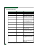
Maintenance Analysis Procedures (MAPS) 3 . Table 3-3 Event Codes versus Maintenance Action Event Code Explanation Action 001 System power-down. Power on director. 010 Login server unable to synchronize databases. Go to MAP 0700. 011 Login server database invalid. Go to MAP 0700. 020 Name server unable to synchronize databases. Go to MAP 0700. 021 Name server database invalid. Go to MAP 0700. 031 SNMP request received from unauthorized community.
Maintenance Analysis Procedures (MAPS) 3 Table 3-3 3-4 Event Codes versus Maintenance Action (continued) Event Code Explanation Action 074 ILS frame delivery error threshold exceeded. Event data intended for engineering evaluation. Perform data collection procedure (Collecting Maintenance Data on page 4–39) and return CD to McDATA support personnel. 080 Unauthorized worldwide name. Go to MAP 0600. 081 Invalid attachment. Go to MAP 0600. 090 Database replication time out.
Maintenance Analysis Procedures (MAPS) 3 Table 3-3 Event Codes versus Maintenance Action (continued) Event Code Explanation Action 121 Zone set activation failed - zone set too large. Reduce size of zone set and retry. 140 Congestion detected on an ISL. Go to MAP 0700. 141 Congestion relieved on an ISL. No action required. 142 Low BB_Credit detected on an ISL. Go to MAP 0700. 143 Low BB_Credit relieved on an ISL. No action required. 150 Zone merge failure. Go to MAP 0700.
Maintenance Analysis Procedures (MAPS) 3 Table 3-3 3-6 Event Codes versus Maintenance Action (continued) Event Code Explanation Action 310 Cooling fan propeller recovered. No action required. 311 Cooling fan propeller recovered. No action required. 312 Cooling fan propeller recovered. No action required. 313 Cooling fan propeller recovered. No action required. 314 Cooling fan propeller recovered. No action required. 315 Cooling fan propeller recovered. No action required.
Maintenance Analysis Procedures (MAPS) 3 Table 3-3 Event Codes versus Maintenance Action (continued) Event Code Explanation Action 431 Excessive Ethernet receive errors. Go to MAP 0400. 432 Ethernet adapter reset. Go to MAP 0400. 433 Non-recoverable Ethernet fault. Go to MAP 0500. 440 Embedded port hardware failed. Go to MAP 0500. 442 Embedded port anomaly detected. No action required. 445 ASIC detected a system anomaly. No action required. 450 Serial number mismatch detected.
Maintenance Analysis Procedures (MAPS) 3 Table 3-3 3-8 Event Codes versus Maintenance Action (continued) Event Code Explanation Action 513 SFP optical transceiver hot-removal completed. No action required. 514 SFP optical transceiver failure. Go to MAP 0600. 581 Implicit incident. Go to MAP 0600. 582 Bit error threshold exceeded. Go to MAP 0600. 583 Loss of signal or loss of synchronization. Go to MAP 0600. 584 Not operational primitive sequence received. Go to MAP 0600.
Maintenance Analysis Procedures (MAPS) 3 Table 3-3 Event Codes versus Maintenance Action (continued) Event Code Explanation Action 810 High temperature warning (CTP card thermal sensor). Go to MAP 0500. 811 Critically hot temperature warning (CTP card thermal sensor). Go to MAP 0500. 812 CTP card shutdown due to thermal violation. Go to MAP 0500. 850 System shutdown due to CTP card thermal violations. Go to MAP 0500.
Maintenance Analysis Procedures (MAPS) 3 — The user name, maintenance password, and management server name. All are case sensitive and required when prompted at the EFCM Log In or SANavigator Log In dialog box. • If performing fault isolation using a customer-supplied server accessing the SANpilot interface, the administrator user name and password. Both are case sensitive and required when prompted at the Username and Password Required dialog box.
Maintenance Analysis Procedures (MAPS) 3 4 Did the management server or customer-supplied server crash and display a blue screen with the system dump file in hexadecimal format (blue screen of death)? NO ↓ YES A management server or customer-supplied server application problem is indicated. Event codes are not recorded. Go to MAP 0300: Server Application Problem Determination on page 3-49. Exit MAP. 5 Is the SAN management application (EFCM or SANavigator) active? NO ↓ YES Go to step 7.
Maintenance Analysis Procedures (MAPS) 3 c. Wait approximately 30 seconds and press the power ( ) button on the liquid crystal display (LCD) panel to power on the server and perform power-on self-tests (POSTs). During POSTs: 1. The green LCD panel illuminates. 2. The green hard disk drive (HDD) LED blinks momentarily, and processor speed and random-access memory information display momentarily at the LCD panel. 3.
Maintenance Analysis Procedures (MAPS) 3 Figure 3-3 EFCM Log In or SANavigator Log In Dialog Box f. Type a user ID and password, and click Login. The SAN management application opens and the EFCM or SANavigator main window displays (Figure 3-4).
Maintenance Analysis Procedures (MAPS) 3 Figure 3-4 Main Window: Example (EFCM or SANavigator) Did the main window display and does the SAN management application appear operational? YES ↓ NO A management server or customer-supplied server hardware problem is indicated. Event codes are not recorded. Go to MAP 0800: Server Hardware Problem Determination on page 3-121. Exit MAP. 7 Inspect the status symbol associated with the Intrepid 6064 Director at the main window physical map or product list.
Maintenance Analysis Procedures (MAPS) 3 the status of the director or the status of the link between the management server or customer-supplied server and the director: • No status symbol indicates that the director is operational. • A yellow triangle indicates that the director is operating in degraded mode. • A red diamond indicates that the director is not operational. • A grey square with yellow exclamation mark indicates that the status of the director is unknown.
Maintenance Analysis Procedures (MAPS) 3 9 At the director, inspect the amber LED at the top of each CTP2 card. Is the amber LED illuminated on both CTP2 cards? NO ↓ YES Failure of both CTP2 cards is indicated. Event codes are not recorded. Go to MAP 0500: FRU Failure Analysis on page 3-75. Exit MAP. 10 A director-to-server Ethernet link failure is indicated. Go to step 23 to obtain event codes. If no event codes are found, go to MAP 0400: Loss of Server Communication on page 3-57. Exit MAP.
Maintenance Analysis Procedures (MAPS) 3 13 Blinking red and yellow diamonds overlay both serial crossbar (SBAR) assembly graphics or both fan module graphics. Redundant FRU failures are indicated. Go to step 23 to obtain event codes. If no event codes are found, go to MAP 0500: FRU Failure Analysis on page 3-75. Exit MAP. 14 Is a yellow triangle (attention indicator) associated with the icon representing the director reporting the problem? YES ↓ NO Go to step 18.
Maintenance Analysis Procedures (MAPS) 3 17 A blinking red and yellow diamond overlays a control processor (CTP2) card, SBAR assembly, or fan module graphic. A FRU failure is indicated. Go to step 23 to obtain event codes. If no event codes are found, go to MAP 0500: FRU Failure Analysis on page 3-75. Exit MAP. 18 No colored status symbol is associated the icon representing the director reporting the problem. Although the director is operational, a minor problem may exist.
Maintenance Analysis Procedures (MAPS) 3 YES ↓ NO The director appears operational. Exit MAP. Go to step 2. 20 Does a yellow triangle (attention indicator) overlay a port card graphic? YES ↓ NO Go to step 22. 21 Inspect the port state and LED status for all port cards with an attention indicator. a. Double-click the port card to open the Port Card View. At the Port Card View, double-click the port graphic with the attention indicator. The Port Properties dialog box displays (Figure 3-5). b.
Maintenance Analysis Procedures (MAPS) 3 NO ↓ YES Expansion port (E_Port) segmentation is indicated. Go to step 23 to obtain event codes. If no event codes are found, go to MAP 0700: Fabric, ISL, and Segmented Port Problem Determination on page 3-105. Exit MAP. A message displays indicating a link incident problem. Go to step 23 to obtain event codes. If no event codes are found, go to MAP 0600: Port Card Failure and Link Incident Analysis on page 3-83. Exit MAP.
Maintenance Analysis Procedures (MAPS) 3 Did one of the listed messages appear in the Link Incident Log? YES ↓ NO The director appears operational. Exit MAP. A link incident problem is indicated. Go to step 23 to obtain event codes. If no event codes are found, go to MAP 0600: Port Card Failure and Link Incident Analysis on page 3-83. Exit MAP. 23 Obtain event codes from the Intrepid 6064 Event Log. NOTE: If multiple event codes are found, note all codes and associated severity levels.
Maintenance Analysis Procedures (MAPS) 3 24 Are you at the director reporting the problem? YES ↓ NO Go to step 36. 25 Is the power LED (green) at the director front bezel illuminated? NO ↓ YES Go to step 30. 26 Is the director connected to facility AC power and powered on? NO ↓ YES Go to step 29. 27 Connect the director to facility AC power and set the power switch (circuit breaker) at the rear of the director to the ON (up) position.
Maintenance Analysis Procedures (MAPS) 3 fan module, and the module must be removed and replaced (RRP: Fan Module on page 5-30). Exit MAP. 29 Inspect the director for indications of being powered on: • At the front bezel, an illuminated power LED (green) or system error LED (amber). • An illuminated green LED on the active CTP2 card, and illuminated green PWR OK LEDs on both power supplies. • Audio emanations and airflow from cooling fans.
Maintenance Analysis Procedures (MAPS) 3 Was unit beaconing enabled because a director failure or degradation was suspected? YES ↓ NO The director appears operational. Exit MAP. Go to step 24. 32 Is the system error LED (amber) at the director front bezel illuminated? YES ↓ NO The director appears operational. Verify operation at the management server or customer-supplied server. Go to step 3.
Maintenance Analysis Procedures (MAPS) 3 35 Is the green PWR OK LED on a power supply extinguished? NO ↓ YES A power supply failure is indicated. Go to step 23 to obtain event codes. If no event codes are found, go to MAP 0100: Power Distribution Analysis on page 3-34. Exit MAP. The director appears operational. Exit MAP.
Maintenance Analysis Procedures (MAPS) 3 Figure 3-8 Username an d Password Required Dialog Box d. Type the user name and password, and click OK. The SANpilot interface opens with the View panel displayed (Figure 3-9). Continue.
Maintenance Analysis Procedures (MAPS) 3 39 Does the SANpilot interface appear operational with the View panel displayed? NO ↓ YES Go to step 44. 40 A Page cannot be found, Unable to locate the server, HTTP 404 file not found, or other similar message appears. The message indicates the web browser PC cannot communicate with the director because: • The director-to-PC Internet link could not be established. • AC power distribution in the director failed, or AC power was disconnected.
Maintenance Analysis Procedures (MAPS) 3 42 At the director, inspect the amber LED at the top of each CTP2 card. Is the amber LED illuminated on both CTP2 cards? NO ↓ YES Failure of both CTP2 cards is indicated. Event codes are not recorded. Go to MAP 0500: FRU Failure Analysis on page 3-75. Exit MAP. 43 A director-to-PC Internet link problem (Internet too busy or IP address typed incorrectly) is indicated. a. Wait approximately five minutes, then attempt to login to the director again. b.
Maintenance Analysis Procedures (MAPS) 3 a. At the View panel, click the Port Properties tab. The View panel (Port Properties tab) displays with port 0 highlighted (Figure 3-10). b. Inspect the Beaconing and Operational State fields. Figure 3-10 SANpilot Interface, View Panel Does the Beaconing field display an On message? YES ↓ NO Go to step 47. 46 Port beaconing is enabled. a. Consult the customer and next level of support to determine the reason port beaconing is enabled. b.
Maintenance Analysis Procedures (MAPS) 3 2. Click the Beaconing State check box for the port. The check mark disappears from the box and port beaconing is disabled. 3. Return to the View panel (Port Properties tab). Continue. 47 At the View panel, does the Operational State field display a Segmented message? NO ↓ YES Port segmentation is indicated. Go to step 52 to obtain event codes. If no event codes are found, go to MAP 0700: Fabric, ISL, and Segmented Port Problem Determination on page 3-105.
Maintenance Analysis Procedures (MAPS) 3 Figure 3-11 SANpilot Interface, View Panel Does the Status field display a Failed message for either power supply? NO ↓ YES A power supply failure is indicated. Go to step 52 to obtain event codes. If no event codes are found, go to MAP 0100: Power Distribution Analysis on page 3-34. Exit MAP. 51 Inspect the Status fields for director FRUs, including CTP2 cards, SBAR assemblies, fan modules, and the backplane.
Maintenance Analysis Procedures (MAPS) 3 Does the State field display a Failed message for any of the FRUs? YES ↓ NO The director appears operational. Exit MAP. A FRU failure is indicated. Continue to the next step to obtain event codes. If no event codes are found, go to MAP 0500: FRU Failure Analysis on page 3-75. Exit MAP. 52 Obtain event codes from the SANpilot event log. NOTE: If multiple event codes are found, note all codes and associated severity levels.
Maintenance Analysis Procedures (MAPS) 3 Figure 3-12 SANpilot Interface, Monitor Panel Were one or more event codes found? NO ↓ YES Go to Table 3-3 on page 3-3 to interpret event codes. Return to the MAP step that sent you here. 53 You are at the console of an open systems interconnection (OSI) or Fibre Connection (FICON) server attached to the director reporting the problem.
Maintenance Analysis Procedures (MAPS) 3 54 The link incident record provides the attached director port numbers and one or more of the following event codes and messages. Record all event codes that may relate to the reported problem. 581 - Link interface incident - implicit incident. 582 - Link interface incident - bit-error threshold exceeded. 583 - Link failure - loss of signal or loss of synchronization. 584 - Link failure - not-operational primitive sequence (NOS) received.
Maintenance Analysis Procedures (MAPS) 3 2 Table 3-4 lists event codes, brief explanations of the codes, and the associated steps that describe fault isolation procedures. MAP 100: Event Codes Table 3-4 Event Code Explanation Action 200 Power supply AC voltage failure. Go to step 3. 201 Power supply DC voltage failure. Go to step 3. 202 Power supply thermal failure. Go to step 7. 208 Power supply false shutdown. Go to step 8.
Maintenance Analysis Procedures (MAPS) 3 Is a failure indicated? YES ↓ NO The director appears operational. Exit MAP. 5 Ensure the power supply is correctly installed and seated in the director. If required, partially remove and reseat the power supply. Was a corrective action performed? YES ↓ NO Go to step 7. 6 Verify redundant power supply operation. a. Inspect the power supply and ensure the green PWR OK LED illuminates and all amber LEDs extinguish. b.
Maintenance Analysis Procedures (MAPS) 3 Contact the next level of support. Exit MAP. 8 Power sense circuitry is defective in the indicated power supply or there is a problem with facility input power. Have the customer inspect and verify that facility power is within specifications. These specifications are: • One single-phase connection for each power supply. • Input power between 100 and 240 VAC, and between 2 and 4 amps. • Input frequency between 47 and 63 Hz.
Maintenance Analysis Procedures (MAPS) 3 10 Is fault isolation being performed at the director? YES ↓ NO Fault isolation is being performed at the management server, customer-supplied server, or SANpilot interface. Go to step 21. 11 Verify the director is connected to facility power and is powered on. a. Ensure AC power cords (PS0 and PS1) are connected to the rear of the director and to facility power receptacles. If not, connect the cords as directed by the customer. b.
Maintenance Analysis Procedures (MAPS) 3 13 Does inspection of a power supply indicate a failure (green PWR OK LED extinguished and one or more amber LEDs illuminated)? NO ↓ YES A redundant power supply failed. Go to step 7. The director appears operational. Exit MAP. 14 The director AC power distribution system failed. Possible causes include failure of: • Both power supplies. • Power module assembly. • Backplane.
Maintenance Analysis Procedures (MAPS) 3 YES ↓ NO The director appears operational. Exit MAP. 17 Both power supplies failed and must be removed and replaced. (RRP: Power Supply on page 5-22). Perform the data collection procedure as part of FRU removal and replacement. ATTENTION! Do not remove a power supply unless a replacement is immediately available. To avoid director overheating, a power supply must be replaced within five minutes.
Maintenance Analysis Procedures (MAPS) 3 20 The backplane failed and must be removed and replaced (RRP: Backplane on page 5-36). • This procedure is nonconcurrent and must be performed while director power is off. • Perform the data collection procedure as part of FRU removal and replacement. Did backplane replacement solve the problem? NO ↓ YES The director appears operational. Exit MAP. Contact the next level of support. Exit MAP.
Maintenance Analysis Procedures (MAPS) 3 • AC power distribution in the director failed, or AC power was disconnected. • Both of the director CTP2 cards failed. Continue. 24 Ensure the director reporting the problem is connected to facility AC power and the power switch (circuit breaker) at the rear of the director is set to the ON (up) position. Inspect the director for indications of being powered on: • At the front bezel, an illuminated power LED (green) or system error LED (amber).
Maintenance Analysis Procedures (MAPS) 3 Continue. 27 Ensure the director reporting the problem is connected to facility AC power and the power switch (circuit breaker) at the rear of the director is set to the ON (up) position. Inspect the director for indications of being powered on: • At the front bezel, an illuminated power LED (green) or system error LED (amber). • An illuminated green LED on the active CTP2 card. • At least one green PWR OK LED illuminated on a power supply.
Maintenance Analysis Procedures (MAPS) 3 MAP 0200: POST Failure Analysis When the director is powered on, it performs a series of power-on self-tests (POSTs). When POSTs complete, the director performs an initial program load (IPL) that loads firmware and brings the unit online. This MAP describes fault isolation for problems that may occur during the POST/IPL. If an error is detected, the POST/IPL continues in an attempt to initialize the director and bring it online.
Maintenance Analysis Procedures (MAPS) 3 3 Table 3-5 lists event codes, brief explanations of the codes, and the associated steps that describe fault isolation procedures. Table 3-5 Event Code MAP 200: Event Codes Explanation Action 400 Power-up diagnostic failure. Go to step 4. 411 Firmware fault. Go to step 11. 413 Backup CTP2 card POST failure. Go to step 12. 4 POST/IPL diagnostics detected a FRU failure. a.
Maintenance Analysis Procedures (MAPS) 3 5 The backplane failed POSTs (indicated by a FRU code 01) and must be removed and replaced (RRP: Backplane on page 5-36). • This procedure is nonconcurrent and must be performed while director power is off. • Perform the data collection procedure as part of FRU removal and replacement. Did backplane replacement solve the problem? NO ↓ YES The director appears operational. Exit MAP. Contact the next level of support. Exit MAP.
Maintenance Analysis Procedures (MAPS) 3 • Perform the data collection procedure as part of FRU removal and replacement. Did SBAR assembly replacement solve the problem? NO ↓ YES The director appears operational. Exit MAP. Contact the next level of support. Exit MAP. 8 A fan module failed POSTs (indicated by a FRU code 05) and must be removed and replaced (RRP: Fan Module on page 5-30). • This procedure is concurrent and can be performed while director power is on.
Maintenance Analysis Procedures (MAPS) 3 Did power supply replacement solve the problem? NO ↓ YES The director appears operational. Exit MAP. Contact the next level of support. Exit MAP. 10 A port card failed POSTs (indicated by FRU codes 08 through 0F) and must be removed and replaced (RRP: Port Module Card (UPM and XPM) on page 5-11). • This procedure is concurrent and can be performed while director power is on. • Perform the data collection procedure as part of FRU removal and replacement.
Maintenance Analysis Procedures (MAPS) 3 Did CTP2 card replacement solve the problem? NO ↓ YES The director appears operational. Exit MAP. Contact the next level of support. Exit MAP.
Maintenance Analysis Procedures (MAPS) 3 Figure 3-13 Windows Security Dialog Box b. Click Task Manager. The Windows Task Manager dialog box displays with the Applications page open (Figure 3-14). Figure 3-14 Windows Task Manager Dialog Box (Applications Page) c. Select (highlight) the EFCM or SANavigator entry and click End Task. The SAN management application closes. Continue.
Maintenance Analysis Procedures (MAPS) 3 3 Attempt to clear the problem by rebooting the management server or customer-supplied server PC. If the customer-supplied server does not use the Windows 2000 operating system, refer to the supporting documentation to reboot the server. a. At the Windows 2000 desktop, click Start at the left side of the task bar (bottom of the desktop), then select Shut Down. The Shut Down Windows dialog box displays (Figure 3-15). Figure 3-15 Shut Down Windows Dialog Box b.
Maintenance Analysis Procedures (MAPS) 3 4. Ignore the message. After ten seconds, the server performs the boot sequence from the BIOS. During the boot sequence, the server performs additional POSTs and displays the following operational information at the LCD panel: • Host name. • System date and time. • LAN 1 and LAN 2 IP addresses. • Fan 1, fan 2, fan 3, and fan 4 rotational speed. • CPU temperature. • Hard disk capacity. • Virtual and physical memory capacity. d.
Maintenance Analysis Procedures (MAPS) 3 NO ↓ YES A SAN management application error occurred. Click OK to close the window and close the application. Go to step 3. 5 Did the SAN management application display a window with the message The software version on this management server is not compatible with the version on the remote management server? YES ↓ NO Go to step 8. 6 The SAN management applications running on the management server and client workstation are not at compatible release levels.
Maintenance Analysis Procedures (MAPS) 3 9 Did the Element Manager application display a window with the message Send firmware failed? YES ↓ NO Go to step 11. 10 An attempt to download a firmware version from the management server or customer-supplied server hard drive to the director failed. Retry the operation (Managing Firmware Versions on page 4-56). Did the firmware version download to the director? NO ↓ YES The management server or customer-supplied server appears operational. Exit MAP.
Maintenance Analysis Procedures (MAPS) 3 Figure 3-17 Dr. Watson for Windows 2000 Dialog Box YES ↓ NO Go to step 14. A SAN management application error occurred and transmitted a handling exception event to the operating system. a. Click Cancel to close the Dr. Watson for Windows 2000 dialog box and SAN management application. b. Using the My Computer function at the Windows 2000 desktop, copy the crash dump file (user.dmp) from the local disk (C:) to the CD-RW drive (D:). c.
Maintenance Analysis Procedures (MAPS) 3 14 Did the management server or customer-supplied server crash and display a blue screen with the system dump file in hexadecimal format (blue screen of death)? YES ↓ NO The management server or customer-supplied server appears operational. Exit MAP. 15 Attempt to clear the problem by power cycling the management server or customer-supplied server PC.
Maintenance Analysis Procedures (MAPS) 3 • Fan 1, fan 2, fan 3, and fan 4 rotational speed. • CPU temperature. • Hard disk capacity. • Virtual and physical memory capacity. c. After successful POST completion, the LCD panel displays a Welcome!! message, then continuously cycles through and displays server operational information. d.
Maintenance Analysis Procedures (MAPS) 3 • At the Hardware View, a grey square at the alert panel, a No Link status and reason at the Intrepid 6064 Status table, and no FRUs visible for the director. • At the web browser PC, A Page cannot be found, Unable to locate the server, HTTP 404 - file not found, or similar message.
Maintenance Analysis Procedures (MAPS) 3 3 Is fault isolation being performed at the management server or customer-supplied server? YES ↓ NO Fault isolation is being performed through the SANpilot interface. Go to step 24. 4 At the EFCM or SANavigator main window, is a grey square with yellow exclamation mark associated with the icon representing the director reporting the problem? YES ↓ NO The director-to-server connection is restored and appears operational. Exit MAP.
Maintenance Analysis Procedures (MAPS) 3 Does the director appear powered on? YES ↓ NO A power distribution problem is indicated. Go to MAP 0100: Power Distribution Analysis on page 3-34. Exit MAP. 6 At the director, inspect the amber LED at the top of each CTP2 card. Is the amber LED illuminated on both CTP2 cards? NO ↓ YES Failure of both CTP2 cards is indicated. Go to MAP 0500: FRU Failure Analysis on page 3-75. Exit MAP. 7 The director-to-server Ethernet link failed.
Maintenance Analysis Procedures (MAPS) 3 8 Transmit or receive errors for a director Ethernet adapter (on each CTP2 card) exceeded a threshold, the director-to-server link was not connected, or the director-to-server link timed out. A problem with the Ethernet cable, Ethernet hub or hubs, or other LAN-attached device is indicated. Verify the director is connected to the management server or customer-supplied server through one or more Ethernet hubs. a.
Maintenance Analysis Procedures (MAPS) 3 Figure 3-19 Ethernet Hubs, Daisy-Chained NOTE: To check two hubs, use step a and step b (top and middle hub instructions only). a. At the first (top) Ethernet hub, ensure an RJ-45 Ethernet patch cable connects to port 24 and the medium-dependent interface (MDI) switch is set to MDI (in). b.
Maintenance Analysis Procedures (MAPS) 3 • Green Status LEDs illuminated. Is a hub failure indicated? YES ↓ NO Go to step 13. 12 Remove and replace the Ethernet hub. Refer to the supporting documentation shipped with the hub for instructions. Did hub replacement solve the problem? NO ↓ YES The director-to-server connection is restored and appears operational. Exit MAP. Contact the next level of support. Exit MAP. 13 A problem with another LAN-attached device is indicated.
Maintenance Analysis Procedures (MAPS) 3 15 A protocol mismatch occurred because the SAN management application and the director firmware are not at compatible release levels. Recommend to the customer that the downlevel version (software or firmware) be upgraded. Does the SAN management application require upgrade? YES ↓ NO Go to step 17. 16 Upgrade the SAN management application (Installing or Upgrading Software on page 4-82).
Maintenance Analysis Procedures (MAPS) 3 Does the customer want the second management server or customer-supplied server configured as a client? YES ↓ NO Power off the management server or customer-supplied server reporting the Duplicate Session communication problem. Exit MAP. 19 Determine the internet protocol (IP) address of the management server or customer-supplied server running the first instance of the SAN management application. a.
Maintenance Analysis Procedures (MAPS) 3 a. At the EFCM or SANavigator main window, select Logout from the SAN menu. The application logs out and the EFCM Log In or SANavigator Log In dialog box displays (Figure 3-3). b. Type a user name and password. c. Type the IP address of the management server or customersupplied server running the first instance of the SAN management application in the Network Address field. d. Click Login.
Maintenance Analysis Procedures (MAPS) 3 e. At the Windows Workstation menu, sequentially select Programs, Accessories, Hyperterminal, and HyperTerminal. The Connection Description dialog box displays (Figure 3-21). Figure 3-21 Connection Description Dialog Box f. Type Intrepid 6064 in the Name field and click OK. The Connect To dialog box displays (Figure 3-22). Figure 3-22 Connect To Dialog Box g.
Maintenance Analysis Procedures (MAPS) 3 Figure 3-23 COMn Properties Dialog Box h. Configure the Port Settings parameters as follows: — Bits per second - 57600. — Data bits - 8. — Parity - None. — Stop bits - 1. — Flow control - Hardware or None. When the parameters are set, click OK. The Intrepid 6064 HyperTerminal dialog box displays. i. At the > prompt, type the user-level password (the default is password) and press Enter. The password is case sensitive.
Maintenance Analysis Procedures (MAPS) 3 Figure 3-24 Intrepid 6064 - HyperTerminal Dialog Box k. Record the director IP address. l. Select Exit from the File pull-down menu to close the HyperTerminal application. A HyperTerminal dialog box displays (Figure 3-25). Figure 3-25 HyperTerminal Dialog Box m. Click Yes. A second HyperTerminal dialog box displays (Figure 3-26). Figure 3-26 HyperTerminal Dialog Box n. Click No to exit and close the HyperTerminal application.
Maintenance Analysis Procedures (MAPS) 3 o. Power off the maintenance terminal. p. Disconnect the RS-232 null modem cable from the director and the maintenance terminal. Replace the protective cap over the maintenance port. Continue. 22 Define the director IP address to the management server or customer-supplied server. a. At the SAN management application (EFCM or SANavigator main window), select the Setup option from the Discover menu. The Discover Setup dialog box displays (Figure 3-27).
Maintenance Analysis Procedures (MAPS) 3 Figure 3-28 Editing Domain Information Dialog Box c. Click Yes. The Domain Information dialog box displays with the IP Address page open (Figure 3-29). Figure 3-29 Domain Information Dialog Box (IP Address Page) d. Type the correct IP address in the IP Address field. e. Click OK to save the new IP address, close the dialog box, and redefine the director to the SAN management application. f.
Maintenance Analysis Procedures (MAPS) 3 23 An incorrect product type is defined to the management server or customer-supplied server. a. Right-click the product icon with a grey square and yellow exclamation mark (representing the director reporting the problem) at the SAN management application physical map. A pop-up menu appears. b. Select the Delete option from the pop-up menu. The EFCM or SANavigator Message dialog box displays (Figure 3-30). Figure 3-30 EFCM or SANavigator Message Dialog Box c.
Maintenance Analysis Procedures (MAPS) 3 f. Type a director description in the Description field. g. Type the IP address (determined by the customer network administrator) in the IP Address field. h. Type the subnet mask (determined by the customer network administrator) in the Subnet Mask field. i. At the Data Source for Domain area of the dialog box, select the Use auto detection, Use the server, or Use a specific RDC radio button (determined by the customer network administrator). j.
Maintenance Analysis Procedures (MAPS) 3 Continue. 26 Ensure the director reporting the problem is connected to facility AC power and the power switch (circuit breaker) at the rear of the director is set to the ON (up) position. Inspect the director for indications of being powered on: • At the front bezel, an illuminated power LED (green) or system error LED (amber). • An illuminated green LED on the active CTP2 card, and illuminated green PWR OK LEDs on both power supplies.
Maintenance Analysis Procedures (MAPS) 3 Does the SANpilot interface appear operational with the View panel displayed? NO YES ↓ The director-to-SANpilot PC connection is restored and appears operational. Exit MAP. Failure of the CTP2 card Ethernet port is indicated. Go to MAP 0500: FRU Failure Analysis on page 3-75. Exit MAP. MAP 0500: FRU Failure Analysis This MAP describes fault isolation for the CTP2 card, SBAR assembly, and fan module.
Maintenance Analysis Procedures (MAPS) 3 2 Table 3-9 lists event codes, brief explanations of the codes, and associated steps that describe fault isolation procedures. Table 3-9 Event Code 3-76 MAP 500: Event Codes Explanation Action 300 Cooling fan propeller failed. Go to step 5. 301 Cooling fan propeller failed. Go to step 5. 302 Cooling fan propeller failed. Go to step 5. 303 Cooling fan propeller failed. Go to step 5. 304 Cooling fan propeller failed. Go to step 5.
Maintenance Analysis Procedures (MAPS) 3 MAP 500: Event Codes (continued) Table 3-9 Event Code Explanation Action 811 Critically hot temperature warning (CTP2 card thermal sensor). Go to step 7. 812 CTP2 card shutdown due to thermal violation. Go to step 7. 850 System shutdown due to CTP2 card thermal violations. Go to step 7.
Maintenance Analysis Procedures (MAPS) 3 ATTENTION! Do not remove a fan module unless the replacement module is available. Operation of the director with only one fan module for an extended period may cause one or more thermal sensors to post event codes. Do the fan modules appear to function? NO ↓ YES The director appears operational. Exit MAP. Contact the next level of support. Exit MAP. 6 Inspect the faceplates of both CTP2 cards at the front of the director.
Maintenance Analysis Procedures (MAPS) 3 Is the amber LED on an SBAR assembly illuminated but not blinking (beaconing)? YES ↓ NO The director appears operational. Exit MAP. 9 An SBAR assembly failed and must be removed and replaced (RRP: SBAR Assembly on page 5-26). • This procedure is concurrent and can be performed while director power is on. • Perform the data collection procedure as part of FRU removal and replacement.
Maintenance Analysis Procedures (MAPS) 3 13 Does a blinking red and yellow diamond (failed FRU indicator) appear to overlay an SBAR assembly graphic at the Hardware View? NO ↓ YES An SBAR assembly failure is indicated. Go to step 9. 14 At the Hardware View, does a grey square appear at the alert panel, a No Link status appear at the Intrepid 6064 Status table, and graphical FRUs appear uninstalled? YES ↓ NO A green circle appears at the alert panel and the director appears operational. Exit MAP.
Maintenance Analysis Procedures (MAPS) 3 firmware version to download from the management server or customer-supplied server. Download the firmware (Download a Firmware Version to a Director on page 4-64). Perform the data collection procedure after the download. Continue. 17 Did the firmware download solve the problem? NO ↓ YES The director appears operational. Exit MAP. An SBAR assembly failure is indicated. Go to step 9. 18 Does the SANpilot interface appear operational? NO ↓ YES Go to step 22.
Maintenance Analysis Procedures (MAPS) 3 • At least one green PWR OK LED illuminated on a power supply. • Audio emanations and airflow from cooling fans. Does the director appear powered on? YES ↓ NO Analysis for an AC power distribution failure is not described in this MAP. Go to MAP 0000: Start MAP on page 3-9. If this is the second time at this step, contact the next level of support. Exit MAP. 21 At the director, inspect the amber LED at the top of each CTP2 card.
Maintenance Analysis Procedures (MAPS) 3 Does the Status field display a Failed message for either SBAR assembly? NO ↓ YES An SBAR assembly failure is indicated. Go to step 9. The director appears operational. Exit MAP. MAP 0600: Port Card Failure and Link Incident Analysis This MAP describes fault isolation for UPM and XPM cards, SFP and XFP optical transceivers, and Fibre Channel link incidents.
Maintenance Analysis Procedures (MAPS) 3 YES ↓ NO Go to step 4. 3 Table 3-10 lists event codes, brief explanations of the codes, and associated steps that describe fault isolation procedures. Table 3-10 Event Code 3-84 MAP 600: Event Codes Explanation Action 080 Unauthorized worldwide name. Go to step 18. 081 Invalid attachment. Go to step 19. 504 Port card failure. Go to step 6. 505 Port card revision not supported. Go to step 40. 506 Fibre Channel port failure. Go to step 6.
Maintenance Analysis Procedures (MAPS) 3 4 Is fault isolation being performed at the director? YES ↓ NO Fault isolation is being performed at the management server, customer-supplied server, or SANpilot interface. Go to step 8. 5 Inspect the faceplates of port cards at the front of the director. Each card has an amber LED (at the top of the card) that illuminates if the card fails or if any Fibre Channel port fails. Each card also has a bank of amber and green LEDs above the ports.
Maintenance Analysis Procedures (MAPS) 3 Figure 3-32 UPM Card Diagram (OSI) Figure 3-33 UPM Card Diagram (FICON) • Replace the optical transceiver with a transceiver of the same type (shortwave or longwave). • Perform an external loopback test for the port as part of FRU removal and replacement (External Loopback Test (Management Server) on page 4-32). Did optical transceiver replacement solve the problem? NO ↓ YES The director appears operational. Exit MAP.
Maintenance Analysis Procedures (MAPS) 3 • Notify the customer that all ports on the defective card are to be blocked. Ensure the customer system administrator quiesces Fibre Channel frame traffic through any operational ports on the card and sets attached devices offline. • Perform an external loopback test for all ports on the replacement card as part of FRU removal and replacement (External Loopback Test (Management Server) on page 4-32).
Maintenance Analysis Procedures (MAPS) 3 12 Inspect the port state and LED status for all ports with an attention indicator. a. At the Hardware View, double-click the port graphic with the attention indicator. The Port Properties dialog box displays. b. Inspect the Operational State field at the Port Properties dialog box, and the emulated green and amber LEDs adjacent to the port at the Hardware View. c.
Maintenance Analysis Procedures (MAPS) 3 Link interface incident - bit-error threshold exceeded. Link failure - loss of signal or loss of synchronization. Link failure - not-operational primitive sequence (NOS) received. Link failure - primitive sequence timeout. Link failure - invalid primitive sequence received for the current link state. Did one of the listed messages appear in the Link Incident Log? YES ↓ NO The director appears operational. Exit MAP. Go to step 33.
Maintenance Analysis Procedures (MAPS) 3 c. Perform an external loopback test on the port card (External Loopback Test (Management Server) on page 4-32). Did reseating the port card solve the problem? NO ↓ YES The director appears operational. Exit MAP. Go to step 7. 16 An director port is unblocked and receiving the offline sequence (OLS) or not operational sequence (NOS) from an attached device.
Maintenance Analysis Procedures (MAPS) 3 • If a nickname is not assigned to the WWN, the WWN is prefixed by the device manufacturer name. • If a nickname is assigned to the WWN, the nickname appears in place of the WWN. The bound WWN must be entered in the form of a raw WWN format (XX:XX:XX:XX:XX:XX:XX:XX) or must be a valid nickname. Ensure a valid WWN or nickname is entered. Did configuring the WWN or nickname solve the problem? NO ↓ YES The director appears operational. Exit MAP.
Maintenance Analysis Procedures (MAPS) 3 20 The port connection conflicts with the configured port type. Either an expansion port (E_Port) is incorrectly cabled to a Fibre Channel device or a fabric port (F_Port) is incorrectly cabled to a fabric element (director or switch). a. At the management server Hardware View, click Configure and select Ports. The Configure Ports dialog box displays. b.
Maintenance Analysis Procedures (MAPS) 3 Reconfigure the director operating mode: a. Ensure the director is set offline (Set the Director Online or Offline on page 4-43). b. At the Hardware View, click Configure and select Operating Parameters and Fabric Parameters. The Configure Fabric Parameters dialog box displays (Figure 3-34). Figure 3-34 Configure Fabric Parameters Dialog Box c. Select McDATA Fabric 1.0 or Open Fabric 1.0 from the Interop Mode list box. — Select the McDATA Fabric 1.
Maintenance Analysis Procedures (MAPS) 3 22 A loopback (wrap) plug is connected to the port and there is no diagnostic test running. Is a loopback plug in the port receptacle? YES ↓ NO Contact the next level of support. Exit MAP. 23 Remove the loopback plug from the port receptacle. If directed by the customer, connect a fiber-optic jumper cable attaching a device to the director.
Maintenance Analysis Procedures (MAPS) 3 Is the invalid attachment problem solved? YES ↓ NO The Fibre Channel link and director appear operational. Exit MAP. 25 Inspect both SBAR assemblies at the rear of the director. SBAR assembly LEDs can be inspected through the hexagonal cooling vents of the RFI shield. Is the amber LED on an SBAR assembly illuminated but not blinking (beaconing)? YES ↓ NO The director appears operational. Go to step 27.
Maintenance Analysis Procedures (MAPS) 3 a. At the Hardware View, click Configure and select Switch Binding and Change State. The Switch Binding - State Change dialog box displays (Figure 3-35). Figure 3-35 Switch Binding - State Change Dialog Box b. Ensure the Enable Switch Binding checkbox is enabled (checked) for both directors. c. Ensure the Connection Policy radio buttons are compatible for both directors. d. Click Activate for each director or switch.
Maintenance Analysis Procedures (MAPS) 3 Figure 3-36 Fabric Binding Dialog Box b. At the Fabric List section, ensure the Enable/Disable checkbox is enabled (checked) for the fabric containing both directors or switches. c. At the Membership List of section, update the membership list for both elements to ensure interswitch compatibility, then click OK. The fabric binding feature is consistently enabled for both directors or switches.
Maintenance Analysis Procedures (MAPS) 3 Figure 3-37 Switch Binding - Membership List Dialog Box b. At the Switch Binding - Membership List dialog box ensure the Switch Membership List is updated and correct for each director or switch, then click Activate for each director or switch. The switch binding feature is consistently enabled for both directors or switches. Did updating the switch membership lists solve the problem? NO ↓ YES The director appears operational. Exit MAP.
Maintenance Analysis Procedures (MAPS) 3 32 The director and attached device are performing a Fibre Channel link reset. This is a transient state. Wait approximately 30 seconds and inspect port state and LED behavior. Did the link recover and resume operation? NO ↓ YES The Fibre Channel link and director appear operational. Exit MAP. Go to step 1.
Maintenance Analysis Procedures (MAPS) 3 34 Inspect the fiber-optic jumper cable attached to the port and ensure the cable is not bent and connectors are not damaged. If the cable is bent or connectors are damaged: a. Notify the customer the port will be blocked. Ensure the customer system administrator quiesces Fibre Channel frame traffic through the port and sets the attached device offline. b. Block the port (Blocking and Unblocking Ports on page 4-46). c.
Maintenance Analysis Procedures (MAPS) 3 Did the link incident recur? YES ↓ NO The Fibre Channel link and director appear operational. Exit MAP. 37 Disconnect the fiber-optic jumper cable from the director port and connect the cable to a spare port. Is a link incident reported at the new port? YES ↓ NO Go to step 39. 38 The attached device is causing the recurrent link incident. Notify the customer of the problem and have the system administrator: a. Inspect and verify operation of the attached device.
Maintenance Analysis Procedures (MAPS) 3 Continue. 41 Did the firmware download solve the problem? NO ↓ YES The director appears operational. Exit MAP. A port card failure is indicated. Go to step 7. 42 Does the SANpilot interface appear operational? NO ↓ YES Go to step 45. 43 A Page cannot be found, Unable to locate the server, HTTP 404 file not found, or other similar message appears.
Maintenance Analysis Procedures (MAPS) 3 Does the director appear powered on? YES ↓ NO Analysis for an Ethernet link, AC power distribution, or dual CTP2 card failure is not described in this MAP. Go to MAP 0000: Start MAP on page 3-9. If this is the second time at this step, contact the next level of support. Exit MAP. 45 Inspect port card operational states at the SANpilot interface. a. At the View panel, click the FRU Properties tab. The View panel (FRU Properties tab) displays. b.
Maintenance Analysis Procedures (MAPS) 3 Table 3-13 MAP 600: Port Operational States and Actions (SANpilot) Operational State Action Link Reset Go to step 32. Not Installed Go to step 47. 47 Install an SFP optical transceiver in the port receptacle (RRP: Optical Transceiver (SFP and XFP) on page 5-17). a. This procedure is concurrent and can be performed while director power is on. b. Verify the location of the failed port.
Maintenance Analysis Procedures (MAPS) 3 Figure 3-40 UPM Card Diagram (FICON) MAP 0700: Fabric, ISL, and Segmented Port Problem Determination This MAP describes isolation of fabric logout, interswitch link (ISL), and E_Port segmentation problems. Failure indicators include: • An event code recorded at the Intrepid 6064 Event Log or the SANpilot event log. • A segmentation reason associated with a Fibre Channel port at the SANpilot interface.
Maintenance Analysis Procedures (MAPS) 3 2 Table 3-14 lists event codes, brief explanations of the codes, and associated steps that describe fault isolation procedures. Table 3-14 Event Code MAP 700: Event Codes Explanation Action 010 Login server unable to synchronize databases. Go to step 7. 011 Login server database invalid. Go to step 7. 020 Name server unable to synchronize databases. Go to step 7. 021 Name server database invalid. Go to step 7.
Maintenance Analysis Procedures (MAPS) 3 YES ↓ NO Fault isolation is being performed through the SANpilot interface. Go to step 26. 4 At the management server, does a yellow triangle (attention indicator) appear to overlay a port card graphic at the Hardware View? YES ↓ NO The problem is transient and the director-to-fabric element connection appears operational. Exit MAP. 5 Inspect the port state and LED status for all ports with an attention indicator. a.
Maintenance Analysis Procedures (MAPS) 3 Table 3-15 Port Segmentation Reasons and Actions (Management Server) (continued) Segmentation Reason Action Build fabric protocol error. Go to step 17. No principal switch. Go to step 19. No response from attached switch. Go to step 20. 7 A minor error occurred that caused fabric services databases to be re-initialized to an empty state. As a result, a disruptive fabric logout and login occurred for all attached devices.
Maintenance Analysis Procedures (MAPS) 3 • Event code 051 - Following CTP2 card failover, the management server database CRC validation. • Event code 052 - An internal operating error was detected by the management server subsystem. All attached devices resume operation after management server login. Perform the data collection procedure and return the CD to McDATA for analysis. Exit MAP. 9 A minor error occurred that caused fabric controller databases to be re-initialized to an empty state.
Maintenance Analysis Procedures (MAPS) 3 • Intrepid 6140 Director in a multiswitch fabric that has more than 70 ISLs attached. • Other fabric element (other than an Intrepid 6140 Director) in a multiswitch fabric that has more than 32 ISLs attached. Fibre Channel frames may be lost or routed in loops because of potential fabric routing problems.
Maintenance Analysis Procedures (MAPS) 3 Table 3-16 Byte 4 Byte 4, Segmentation Reasons, and Actions (continued) Segmentation Reason Action 04 Build fabric protocol error. Go to step 17. 05 No principal switch. Go to step 19. 06 No response from attached switch. Go to step 20. 13 A director E_Port is connected to an unsupported switch or fabric element. Advise the customer of the problem and disconnect the interswitch link to the unsupported switch. Exit MAP.
Maintenance Analysis Procedures (MAPS) 3 Figure 3-41 Configure Fabric Parameters Dialog Box e. Type the recommended E_D_TOV and R_A_TOV values, then click Activate. f. Repeat step d and step e at the Hardware View for the director attached to the segmented E_Port (second director). Use the same E_D_TOV and R_A_TOV values. g. Set both directors or switches online (Set the Director Online or Offline on page 4-43).
Maintenance Analysis Procedures (MAPS) 3 c. Set both directors or switches offline (Set the Director Online or Offline on page 4-43). d. At the Hardware View for the first director or switch reporting the problem, click Configure and select Operating Parameters and Switch Parameters. The Configure Switch Parameters dialog box displays (Figure 3-42). Figure 3-42 Configure Switch Parameters Dialog Box e. Type the customer-determined preferred domain ID value, then click Activate. f.
Maintenance Analysis Procedures (MAPS) 3 a. Work with the system administrator to determine the desired zone name change for one of the affected directors. Zone names must conform to the following rules: • The name must be 64 characters or fewer in length. • The first character must be a letter (a through z), upper or lower case. • Other characters are alphanumeric (a through z or 0 through 9), dollar sign ($), hyphen (-), caret (^), or underscore (_). b.
Maintenance Analysis Procedures (MAPS) 3 Figure 3-44 Zoning Dialog Box (Active Zone Set Tab) f. Inspect zone names in the active zone set to determine the incompatible name. g. Modify the incompatible zone name as directed by the customer: 1. At the Zoning dialog box, click the Zone Library tab. The dialog box returns to the Zone Library page (Figure 3-43). 2. At the Zones field, right-click the zone name to be changed. A pop-up menu appears. 3. Select the Rename option from the menu.
Maintenance Analysis Procedures (MAPS) 3 17 A director E_Port segmented because a build fabric protocol error was detected. a. Disconnect the fiber-optic jumper cable from the segmented E_Port. b. Reconnect the cable to the same port. Did disconnecting and reconnecting the cable solve the problem and did both directors join through the ISL to form a fabric? NO ↓ YES The directors, associated ISL, and multiswitch fabric appear operational. Exit MAP.
Maintenance Analysis Procedures (MAPS) 3 assigned a priority of 1 and controls the allocation and distribution of domain IDs for all fabric directors and switches (including itself). Principal is the highest priority setting, Default is the next highest, and Never Principal is the lowest priority setting. The setting Never Principal means that the switch is incapable of becoming a principal switch.
Maintenance Analysis Procedures (MAPS) 3 No action is required for an isolated event. However, if this event persists, perform one of the following: • Relieve the congestion by adding parallel ISLs between the directors or switches reporting the problem. • Increase the ISL link speed between the directors or switches reporting the problem (from 1 Gbps to 2 or 10 Gbps). • Reroute Fibre Channel traffic by moving device connections to a less-congested region of the fabric.
Maintenance Analysis Procedures (MAPS) 3 23 A 150 event code indicates a zone merge failed during ISL initialization. Either an incompatible zone set was detected or a problem occurred during delivery of a zone merge frame. This event code always precedes a 070 event code, and represents the reply of an adjacent fabric element in response to a zone merge frame. Obtain supplementary event data for each 150 event code. a. At the Hardware View, click Logs and select Event Log. The Event Log displays. b.
Maintenance Analysis Procedures (MAPS) 3 • Failure reason F1 - An invalid response length condition caused an error in a zone merge frame. • Failure reason F2 - An invalid response code caused an error in a zone merge frame. Disconnect the fiber-optic jumper cable from the E_Port reporting the problem, then reconnect the cable to the same port. Did disconnecting and reconnecting the cable solve the problem and was the resulting zone merge successful? NO ↓ YES The merged zone appears operational.
Maintenance Analysis Procedures (MAPS) 3 27 Inspect the Fibre Channel port segmentation reason at the SANpilot interface. a. At the View panel, click the Port Properties tab. The View panel (Port Properties tab) displays. b. Click the port number (0 through 63) of the segmented port. c. Inspect the Segmentation Reason field for the selected port. Is the Segmentation Reason field blank or N/A? NO ↓ YES The director ISL appears operational. Exit MAP.
Maintenance Analysis Procedures (MAPS) 3 To fault isolate software-related problems with the server, go to MAP 0300: Server Application Problem Determination on page 3-49. To fault isolate director-to-server communication problems, go to MAP 0400: Loss of Server Communication on page 3-57.
Maintenance Analysis Procedures (MAPS) 3 a. Select Shutdown from the SAN menu. An EFCM or SANavigator Message dialog box displays (Figure 3-45). Figure 3-45 EFCM or SANavigator Message Dialog Box b. Click Yes to close the SAN management application. c. Close any other applications. Continue. 5 Inspect the available random access memory (RAM). The server must have a minimum of 128 megabytes (MB) of memory to run the Windows-based operating system and SAN management application. a.
Maintenance Analysis Procedures (MAPS) 3 Figure 3-46 Windows Task Manager Dialog Box Does the computer have sufficient memory? YES ↓ NO A memory upgrade is required. Inform the customer of the problem and contact the next level of support. Exit MAP. 6 Reboot the server and perform system diagnostics. a. At the Windows 2000 desktop, click Start at the left side of the task bar (bottom of the desktop), then select Shut Down. The Shut Down Windows dialog box displays (Figure 3-47).
Maintenance Analysis Procedures (MAPS) 3 Figure 3-47 Shut Down Windows Dialog Box b. Select the Shut Down option from the list box and click OK. The management server powers down. c. Wait approximately 30 seconds and press the power ( ) button on the LCD panel to power on the server and perform POSTs. During POSTs: 1. The green LCD panel illuminates. 2. The green HDD LED blinks momentarily, and processor speed and random-access memory information display momentarily at the LCD panel. 3.
Maintenance Analysis Procedures (MAPS) 3 • Fan 1, fan 2, fan 3, and fan 4 rotational speed. • CPU temperature. • Hard disk capacity. • Virtual and physical memory capacity. d. After successful POST completion, the LCD panel displays a Welcome!! message, then continuously cycles through and displays server operational information. Did POSTs detect a problem? NO ↓ YES A computer hardware problem exists.
Maintenance Analysis Procedures (MAPS) 3 8 At the EFCM Log In or SANavigator Log In dialog box, type a user name and password, and click Login. The SAN management application opens and the EFCM or SANavigator main window displays (Figure 3-4). Did the main window display and does the SAN management application appear operational? NO ↓ YES The server appears operational. Exit MAP.
Maintenance Analysis Procedures (MAPS) 3 3. After a few seconds, the LCD panel displays the following message pertaining to boot sequence selection (Figure 3-50): Boot from LAN? Press Figure 3-50 LCD Panel During Boot Sequence 4. Ignore the message. After ten seconds, the server performs the boot sequence from BIOS. During the boot sequence, the server performs additional POSTs and displays the following operational information at the LCD panel: • Host name. • System date and time.
Maintenance Analysis Procedures (MAPS) 3 11 Re-install the SAN management application (Installing or Upgrading Software on page 4-82). Did the SAN management application install and open successfully? NO ↓ YES The server appears operational. Exit MAP. 12 Advise the customer and next level of support that the server hard drive should be restored to its original factory configuration. If the customer and support personnel do not concur, go to step 13. a. Format the server hard drive.
Maintenance Analysis Procedures (MAPS) 3 3-130 Intrepid® 6064 Director Installation and Service Manual
4 Repair Information This chapter describes repair-related procedures for the Intrepid 6064 Director and associated field-replaceable units (FRUs). The procedures are performed through the storage area network (SAN) management application (SANavigator or EFCM), Intrepid 6064 Element Manager application, or SANpilot interface. The following procedures are described: • Obtaining log information. • Obtaining port diagnostic information. • Performing port diagnostic loopback tests.
Repair Information 4 NOTE: Do not perform repairs until a failure is isolated to a FRU. If fault isolation was not performed, go to MAP 0000: Start MAP on page 3-9. Factory Defaults Table 4-1 lists the defaults for the passwords, and IP, subnet, and gateway addresses. Table 4-1 Factory-Set Defaults Item Procedural Notes Default Customer password password Maintenance password level-2 IP address 10.1.1.10 Subnet mask 255.0.0.0 Gateway address 0.0.0.
Repair Information 4 Obtaining Log Information The SAN management application, Intrepid 6064 Element Manager application, and SANpilot interface provide access to logs with information for administration, operation, and maintenance personnel. • Logs accessed through the SAN management application (SANavigator or EFCM): — Audit Log. — Event Log. — Session Log. — Product Status Log. — Fabric Log. • Logs accessed through the Element Manager application: — Intrepid 6064 Audit Log.
Repair Information 4 SAN Management Logs To open a log from a SAN management application main window, select the Logs option from the Monitor menu, then click (select) the desired log option. Audit Log To open the Audit Log, select the option from the Monitor and Logs menus. The log displays a history of user actions performed through the SAN management application. This information is useful for system administrators and users. For a log description, refer to the SANavigator Software Release 4.
Repair Information 4 • Product - The product associated with the event and configured name or internet protocol (IP) address associated with the instance are displayed. • Data - Additional event data for fault isolation. Include this information when fault isolating a call-home problem, or include the information when reporting an event to customer support. Session Log To open the Session Log, select the option from the Monitor and Logs menus.
Repair Information 4 Fabric Log Element Manager Logs 4-6 • Network Address - The IP address or configured name of the director. This address or name corresponds to the address or name displayed under the product icon at the physical map. • Previous Status - The status of the director prior to the reported status change (Operational, Degraded, Failed, OutofBand Online, or Unknown). An Unknown status indicates the SAN management application cannot communicate with the director.
Repair Information 4 Figure 4-3 Intrepid 6064 Event Log The log displays a history of director events, such as degraded operation, FRU failures, FRU removals and replacements, port problems, Fibre Channel link incidents, and management server-todirector communication problems. The information is useful to maintenance personnel for fault isolation and repair verification. The log contains the following columns: • Date/Time - The date and time the event occurred.
Repair Information 4 The chassis (slot) position for a nonredundant FRU is 0. The chassis positions for redundant FRUs are 0 and 1. The chassis positions for port cards are 0 through 15 inclusive. • Intrepid 6064 Hardware Log Figure 4-4 Event Data - Up to 32 bytes of supplementary event data (if available) in hexadecimal format. See Appendix B, Event Code Tables for an explanation of the supplementary event data.
Repair Information 4 Intrepid 6064 Link Incident Log • Position - A number representing the FRU chassis position. The chassis (slot) position for a nonredundant FRU is 0. The chassis positions for redundant FRUs are 0 and 1. The chassis positions for port cards are 0 through 15 inclusive. • Action - The action performed (Inserted or Removed). • Part Number - The part number of the inserted or removed FRU. • Serial Number - The serial number of the inserted or removed FRU.
Repair Information 4 — Link failure - invalid primitive sequence received for current link state. See MAP 0600: Port Card Failure and Link Incident Analysis on page 3-83 or MAP 0700: Fabric, ISL, and Segmented Port Problem Determination on page 3-105 for corrective actions in response to these link incident messages.
Repair Information 4 Intrepid 6064 Open Trunking Log Figure 4-7 To open the Intrepid 6064 Open Trunking Log, select the Open Trunking Log option from the Logs menu at the Hardware View, Port List View, Node List View, Performance View, or FRU List View. The log displays (Figure 4-7). Intrepid 6064 Open Trunking Log The log displays ISL congestion events that cause Fibre Channel traffic to be routed through an alternate ISL. Entries reflect the traffic re-route status at the managed director.
Repair Information 4 The Logs page provides a Clear Log button for each log. Click the button to delete all entries for the associated log. The Logs page also provides a Clear All Logs button. Click the button to delete all entries in all logs. Figure 4-8 SANpilot Monitor Panel (Logs Page) The Logs tab provides links to the following logs: • Event Log - A listing of messages generated by the product regarding errors and events.
Repair Information 4 Each log contains a link that brings the user to a page of ASCII text that reflects the log information present on the machine at that moment. The log displayed is a snapshot of the current log information. Log entries are displayed in the order in which they occurred, with most recent entries listed first. Each log also contains a Clear Log button that is used to clear all the entries in the log. The Logs page provides a Clear Log button for each log.
Repair Information 4 Table 4-2 Port Operational States (continued) Port State 4-14 Green LED Amber LED Alert Symbol Description Beaconing Off or On Blinking Yellow Triangle The port is beaconing. The amber port LED blinks once every two seconds to enable users to locate the port. Invalid Attachment On Off Yellow Triangle The director port has an invalid attachment state. The reasons for this state display in the Reasons field of the Port Properties dialog box.
Repair Information 4 Management Server Port List View Figure 4-9 To obtain port operational information at the management server (Intrepid 6064 Element Manager application), inspect parameters at the: • Port List View. • Performance View. • Port Properties dialog box. • Port Technology dialog box. At the management server Products View, click the Port List tab. The Port List View displays (Figure 4-9). A row of information for each port (0 through 63 inclusive) appears.
Repair Information 4 • Name - The port name configured through the Configure Ports dialog box. • Block Config - The port status (Blocked or Unblocked). Blocking a port prevents the attached devices or fabric element from communicating. A blocked port continuously transmits the OLS. • State - The port state (Online, Offline, Testing, Beaconing, Invalid Attachment, Link Incident, Link Reset, No Light, Not Operational, Port Failure, Segmented E_Port, or Testing).
Repair Information 4 Performance View Figure 4-10 At the management server, click the Performance tab. The Performance View displays (Figure 4-10). Performance View Each port bar graph in the upper portion of the view displays the instantaneous transmit or receive activity level for the port, and is updated every five seconds. The relative value displayed is the greater of either the transmit or receive activity (whichever value is greatest when sampled).
Repair Information 4 • Open the Port Properties, Node Properties, or Port Technology dialog boxes. • Block or unblock the port. • Enable or disable port beaconing. • Perform port diagnostics. • Enable or disable port channel wrapping (when the director is configured for FICON management style). • Swap one Fibre Channel port address with another (when the director is configured for FICON management style). • Clear link incident alerts. • Reset the port. • Enable or disable port binding.
Repair Information 4 — Sync losses - Synchronization losses are detected because an attached device was reset or disconnected from the port. At the Hardware View, a yellow triangle appears to indicate a link incident. — Signal losses - Signal losses are detected because an attached device was reset or disconnected from the port. At the Hardware View, a yellow triangle appears to indicate a link incident.
Repair Information 4 • Operational statistics - These entries provide information about port operation, including: — Offline sequences received and transmitted. — Link resets received and transmitted. — LIPs generated and detected. • Traffic statistics - These entries provide information about port traffic, including: — Percent link utilization (receive and transmit). — Fibre Channel frames received and transmitted. — Four-byte words received and transmitted. — Flows rerouted to and from ISLs.
Repair Information 4 • Port Name - The user-defined name or description for the port. • Type - The Port type (G_Port, F_Port, or E_Port) type of port (G_Port if nothing is attached to the port, F_Port if a device is attached to the port, and E_Port if the port is connected to another director or switch as part of an ISL). • Operating Speed - The operating speed of the port (Not Established, 1 Gbps, 2 Gbps, or 10 Gbps). • Port WWN - The Fibre Channel WWN for the director port.
Repair Information 4 Port Technology Dialog Box Figure 4-12 • Reason - A summary appears describing the reason if the port state is Segmented E_Port, Invalid Attachment, or Inactive. For any other port state, the reason field is blank or N/A. • Threshold Alert- If a threshold alert exists for the port, an alert indicator (yellow triangle) and the configured name for the alert appear.
Repair Information 4 SANpilot Interface Port List Page Figure 4-13 To obtain port operational information at the SANpilot interface, inspect parameters at the: • Monitor Panel - Port List page. • Monitor Panel - Port Stats page. • View panel - Port Properties page. When the SANpilot interface opens, the View panel appears as the default. At the View panel, select the Monitor option at the left side of the panel. The Monitor panel opens with the Port List page displayed (Figure 4-13).
Repair Information 4 Port Stats Page Figure 4-14 Troubleshooting Tip for Port Statistics 4-24 • State - Port state (Online, Offline, Not Installed, Inactive, Invalid Attachment, Link Reset, No Light, Not Operational, Port Failure, Segmented E_Port, or Testing). • Type - The Port type (G_Port, F_Port, or E_Port) type of port (G_Port if nothing is attached to the port, F_Port if a device is attached to the port, and E_Port if the port is connected to another director or switch as part of an ISL).
Repair Information 4 a link recovery hierarchy implemented in Fibre Channel to handle some level of “expected anomalies”.) For troubleshooting purposes, you want to focus on when the errors, as displayed in the Counter column, increment very quickly. Parts of Statistics Tables Traffic Transmit and Receive Statistics The tables of statistics contain the following columns: • Statistics - the type of statistic being tracked. • # of Wraps - times the Counter value wraps, for statistics that grow rapidly.
Repair Information 4 • Link utilization % Tx - The current link utilization for the port expressed as a percentage. On 1 Gbps links, ports can transmit or receive data at 100 MB per second. On 2 Gbps links, ports can transmit or receive data at 200 MB per second. Link utilization is calculated over one-second intervals.
Repair Information 4 Class 2 Statistics Class 3 Statistics • Delimiter errors - The number of times that the switch detected an unrecognized start-of-frame (SOF), an unrecognized end-of-frame (EOF) delimiter, or an invalid class of service. This indicates that the frame arrived at the switch’s port corrupted. This corruption can be due to plugging/unplugging the link, bad optics at either end of the cable, bad cable, or dirty or poor connections.
Repair Information 4 Open Trunking Statistics Port Properties Page 4-28 • Transmitted Frames - The number of Class 3 frames transmitted by this F_Port to its attached N_Port. • Discarded Frames - The number of Class 3 frames discarded (including multicast frames with bad Domain IDs). • 4-byte words Rx - The number of Class 3, 4-byte words received by the port. • 4-byte words Tx - The number of Class 3, 4-byte words transmitted by the port.
Repair Information 4 Figure 4-15 View Panel (Port Properties Page) The Port Properties page displays information for one port. Values update only when the page opens for a selected port or the user selects Get Port Properties. The page defaults to port 0. Increment or decrement the port number displayed (0 through 63 inclusive) by clicking Fwd>> or <
Repair Information 4 • Port WWN - The Fibre Channel world wide name (WWN) for the port. • Block Configuration - the user-configured state for the port (Blocked or Unblocked). • Beaconing - The user-specified for the port (On or Off). • FAN Configuration - The user-configured state for fabric address notification (FAN) configuration (Enabled or Disabled).
Repair Information 4 Internal Loopback Test (Management Server) To perform an internal loopback at the management server (Intrepid 6064 Element Manager application): 1. Notify the customer a disruptive internal loopback test will be performed on a port or port card. Ensure the customer system administrator quiesces Fibre Channel frame traffic through the port or port card, and sets attached devices offline.
Repair Information 4 7. Click Next. The message Press START TEST to begin diagnostics appears, and the Next button changes to a Start Test button. 8. Click Start Test. The test begins and: a. The Start Test button changes to a Stop Test button. — The message Port xx: TEST RUNNING appears, where xx is the port number. If a port card is tested, the message appears for all ports. b. A red progress bar (indicating percent completion) travels from left to right across the Completion Status field.
Repair Information 4 2. At the management server, open the SAN management application (SANavigator or EFCM). 3. At the SAN management application physical map, right-click the product icon representing the director to be tested, then select Element Manager from the pop-up menu. The application opens. 4. Disconnect the fiber-optic jumper cable from the port to be tested. If a port card will be tested, disconnect all fiber-optic jumper cables.
Repair Information 4 11. Click Start Test. The test begins and: a. The Start Test button changes to a Stop Test button. b. The message Port xx: TEST RUNNING appears. c. A red progress bar (indicating percent completion) travels from left to right across the Completion Status field. NOTE: Click Stop Test at any time to abort the loopback test. 12. When the test completes, results appear as Port xx: Passed! or Port xx: Failed! in the message area of the dialog box. 13.
Repair Information 4 3. Click the Port and Diagnostics tabs. The Port page displays with the Diagnostics tab selected (Figure 4-17). Figure 4-17 Operations Panel (Port Page with Diagnostics Tab) 4. Type the port number to be tested in the Targeted Port Number field. 5. At the Diagnostics Test list box, select the Internal Loopback option. 6. Click Start Port Diagnostics. The test begins and: a. The Start Port Diagnostics button changes to a Terminate Port Diagnostics button. b.
Repair Information 4 b. For the tested port, click (enable) the check box in the Port Reset column. A check mark in the box indicates the port reset option is enabled. c. Click Activate at the bottom of the page. The port resets and the message Your changes have been successfully activated appears. 9. Notify the customer the test is complete and the attached device can be set online. External Loopback Test (SANpilot Interface) To perform an external loopback at the SANpilot interface: 1.
Repair Information 4 10. Remove the loopback plug and reconnect the fiber-optic jumper cable from the device to the port. 11. Reset the tested port: a. Click the Reset tab. The Port page displays with the Reset tab selected. b. For the tested port, click (enable) the check box in the Port Reset column. A check mark in the box indicates the port reset option is enabled. c. Click Activate at the bottom of the page. The port resets and the message Your changes have been successfully activated appears. 12.
Repair Information 4 • Chassis slot number. • The consecutive port numbers on the selected card. Valid port numbers are in the range of 0 through 63 inclusive. c. Double-click the port card with the port to be configured. The Port Card View for the selected card displays. d. Right-click the port to be configured, then select Channel Wrap from the menu. The Channel Wrap On for Port n (where n is the port number) window displays. e. Click OK to enable channel wrapping for the port. 3.
Repair Information 4 Figure 4-18 Swap Ports Dialog Box 5. At the First address and Second address fields, type the logical port addresses (in hexadecimal format) of the pair of ports to be swapped. The ports are automatically blocked during the procedure. Select the Unblock after swap check boxes to unblock the ports when the procedure completes. 6. Click Next. At the Swap Ports dialog box, the message Continuing this procedure requires varying the selected ports offline.
Repair Information 4 NOTE: An optional full-volatility feature is often required at military sites that process classified data. If the feature is enabled through a product feature enablement (PFE) key, a memory dump file (that possibly includes classified Fibre Channel frames) is not included as part of the data collection procedure. Perform the maintenance data collection procedure after a firmware fault is corrected or a failed FRU is replaced to capture the data for analysis.
Repair Information 4 5. At the Save Data Collection dialog box, select the compact disc drive (D:\) from the Look in drop-down menu, then type a descriptive name for the collected maintenance data in the File name field. 6. The Data Collection dialog box (Figure 4-20) displays with a progress bar that shows percent completion of the data collection. When the process reaches 100%, the Cancel button changes to a Close Button. Figure 4-20 Data Collection Dialog Box 7. Click Close to close the dialog box.
Repair Information 4 Figure 4-21 Operations Panel (Maintenance Page with Dump Retrieval Tab) 3. Right-click the CTP Dump link to open a list of menu options. 4. Select the Save Target As menu option. The Save As dialog box displays (Figure 4-22). Figure 4-22 Save As Dialog Box 5. Insert a blank diskette in the floppy drive of the browser PC.
Repair Information 4 6. At the Save As dialog box, select the floppy drive (A:\) from the Save in drop-down menu, type a descriptive name for the dump file in the File name field, and click Save. 7. The Download complete dialog box displays (Figure 4-23) with a progress bar that shows percent completion of the dump file download. Figure 4-23 Download Complete Dialog Box 8. Click Close to close the dialog box. 9.
Repair Information 4 NOTE: When the director is set offline, the operation of attached Fibre Channel devices is disrupted. Do not set the director offline unless directed to do so by a procedural step or the next level of support. Set Online State (Management Server) To set the director online from the management server (Intrepid 6064 Element Manager application): 1. At the management server, open the SAN management application (SANavigator or EFCM). 2.
Repair Information 4 4. Click Set Offline. A warning dialog box displays the message Performing this operation will change the current state to Offline. 5. Click OK. As the director goes offline, inspect the Hardware View. The State field of the Intrepid 6064 Status table displays Offline. Set Online State (SANpilot Interface) To set the director online from the SANpilot interface: 1. When the SANpilot interface opens, the View panel and Switch page appear as the default.
Repair Information 4 2. Click the Online State tab. The Switch page displays with the Online State tab selected (Figure 4-25). 3. Click Set Offline. The director goes offline and the message Your changes have been successfully activated appears. Blocking and Unblocking Ports This section describes procedures to block or unblock director ports. An entire port card can be blocked or unblocked, or ports can be blocked or unblocked on an individual basis.
Repair Information 4 Figure 4-26 Blocking Port Warning Box 7. Click OK. The following occur to indicate the port is blocked and offline: — The emulated green LED associated with the port extinguishes at the Hardware View. — The green LED associated with the port extinguishes at the director. — A check mark displays in the check box adjacent to the Block Port menu option.
Repair Information 4 7. Click OK. The following occur to indicate the port card is blocked and offline: — Emulated green LEDs associated with all ports extinguish at the Hardware View. — Green LEDs associated with all ports extinguish at the director. Unblock a Port (Management Server) To unblock a director port from the management server (Intrepid 6064 Element Manager application): 1. At the management server, open the SAN management application (SANavigator or EFCM). 2.
Repair Information 4 Unblock a Port Card (Management Server) To unblock all ports on a director port card from the management server (Intrepid 6064 Element Manager application): 1. At the management server, open the SAN management application (SANavigator or EFCM). 2. At the SAN management application physical map, right-click the product icon representing the director for which the port is to be unblocked, then select Element Manager from the pop-up menu. The application opens. 3. Click the Hardware tab.
Repair Information 4 Figure 4-28 Configure Panel (Ports Page) 2. Click the check box for the selected port in the Blocked column to block the port (default is unblocked). A check mark in the box indicates the port is blocked. 3. Click Activate at the bottom of the page to save and activate the blocked configuration. The message Your changes to the port configuration have been successfully activated appears. Unblock a Port (SANpilot Interface) To unblock a director port from the SANpilot interface: 1.
Repair Information 4 Cleaning Fiber-Optic Components Perform this procedure as directed in this publication and when connecting or disconnecting fiber-optic cables from port card connectors (if necessary). To clean fiber-optic components: 1. Obtain the appropriate tools (portable can of oil-free compressed air and alcohol pads) from the fiber-optic cleaning kit. 2. Disconnect the fiber-optic cable from the port. Use compressed air to blow any contaminants from the connector (part A of Figure 4-29).
Repair Information 4 Power-On Procedure DANGER Use the supplied power cords. Ensure the facility power receptacle is the correct type, supplies the required voltage, and is properly grounded. To power on the director: 1. One alternating current (AC) power cord is required for each power supply installed. Ensure power cord(s) connect facility power to the input power module at the bottom rear of the director.
Repair Information 4 Power-Off Procedure NOTE: Powering the director off and on (performing a power cycle) resets all logic cards and executes POSTs. When performing a power cycle, wait approximately 30 seconds before switching power on. NOTE: When the director is powered off, the operation of attached Fibre Channel devices is disrupted. Do not power off the director unless directed to do so by a procedural step or the next level of support. To power off the director: 1.
Repair Information 4 • Reload director firmware from FLASH memory. • Reset the Ethernet LAN interface, causing the connection to the management server to drop momentarily until the connection automatically recovers. A director reset is more disruptive and resets the: IML the Director (CTP Front Panel) • Microprocessor and functional logic for the CTP card and reloads the firmware from FLASH memory.
Repair Information 4 3. Select the IPL option from the Maintenance menu. An Information dialog box displays (Figure 4-30). Figure 4-30 Information Dialog Box 4. Click Yes to IPL the director. During the IPL, the director-to-management server Ethernet link drops momentarily and the following occur at the Hardware View: — As the network connection drops, the Intrepid 6064 Status table turns yellow, the Status field displays No Link, and the State field displays Link Timeout.
Repair Information 4 • As the network connection drops, the Intrepid 6064 Status table turns yellow, the Status field displays No Link, and the State field displays Link Timeout. • The status bar at the bottom of the window displays a grey square, indicating director status is unknown. • Illustrated FRUs disappear, and appear again as the connection is re-established. Managing Firmware Versions Firmware is the director operating code stored in FLASH memory on the CTP card.
Repair Information 4 Figure 4-31 Firmware Library Dialog Box 4. The firmware version displays at the lower left corner of the dialog box in XX.YY.ZZ format, where XX is the version level, YY is the release level, and ZZ is the patch level. 5. Click Close to close the dialog box. Add a Firmware Version to the Management Server Library The firmware version shipped with the director is provided on the System Version XX.YY.ZZ CD-ROM.
Repair Information 4 Figure 4-32 McDATA File Center Home Page 2. Select (click) the Login option at the top of the home page. The Login page displays (Figure 4-33). Figure 4-33 McDATA File Center (Login Page) 3. Type the user name and password (assigned and registered while performing Task 14: Register with the McDATA File Center on page 2-120) and click Login. The Welcome page displays. 4. Select (click) the Documents option at the top of the page. The Find Documents page displays (Figure 4-34).
Repair Information 4 Figure 4-34 McDATA File Center (Find Documents Page) 5. Select (highlight) the ED 6064 Firmware option at the list box and click Search. The Documents Match page displays (Figure 4-35) with a list of firmware available for download.
Repair Information 4 6. Authorization to download a firmware version requires approval from the McDATA Solution Center. In the Action column adjacent to the desired firmware version, click Add to Request. The Current Request page displays (Figure 4-36). Figure 4-36 McDATA File Center (Current Request Page) 7. Click Submit Request. The Request Submitted page displays and the request for approval is e-mailed to the McDATA Solution Center.
Repair Information 4 8. In the Action column adjacent to the approved request for the firmware version, click Download. The File Download dialog box displays (Figure 4-38). Figure 4-38 File Download Dialog Box 9. Select the Save this file to disk radio button and click OK. The Save As dialog box appears (Figure 4-39). Figure 4-39 Save As Dialog Box 10.
Repair Information 4 11. The Download complete dialog box displays (Figure 4-40) with a progress bar that shows percent completion of the firmware version download. 12. When the process completes, click Close to close the dialog box. The new firmware version is downloaded and saved to the PC hard drive. Figure 4-40 Download Complete Dialog Box 13. At the PC, close the Internet session. 14.
Repair Information 4 18. Click New. The New Firmware Version dialog box displays (Figure 4-42). Figure 4-42 New Firmware Version Dialog Box 19. Select the desired firmware version file (downloaded in step 1) from the management server diskette drive or hard drive. Ensure the correct directory path and filename appear in the File name field and click Save. The New Firmware Description dialog box displays (Figure 4-43). Figure 4-43 New Firmware Description Dialog Box 20.
Repair Information 4 22. The File Transfer message box converts to a Transfer Complete message box, indicating the new firmware version is stored on the management server hard drive. Click Close to close the message box. 23. The new firmware version and associated description appear in the Firmware Library dialog box. Click Close to close the window and return to the Hardware View. 24. To send the firmware version to a director, see Download a Firmware Version to a Director following.
Repair Information 4 Figure 4-45 Firmware Library Dialog Box 6. Select (highlight) the firmware version to be downloaded and click Send. The send function verifies existence of certain director conditions before the download begins. If an error occurs, a message displays indicating the problem must be fixed before firmware is downloaded. Conditions that terminate the process include: — A redundant CTP card failure. — The firmware version is being installed to the director by another user.
Repair Information 4 b. As the download progresses, a Sending Files message displays. This message remains as a progress bar travels across the dialog box to show percent completion of the download. The bar progresses to 100% when the last file is transmitted to the CTP card. c. As the download finishes, a Writing data to FLASH message displays again for a few moments. d. The director performs an IPL, during which an IPLing message displays at the Send Firmware dialog box.
Repair Information 4 Determine Director Firmware Version To determine a director firmware version from the SANpilot interface: 1. When the SANpilot interface opens, the View panel and Switch page appear as the default. At the View panel, click the Unit Properties tab. The Unit Properties page displays (Figure 4-48). 2. At the bottom of the page, record the firmware version listed in the Firmware Level field.
Repair Information 4 1. Obtain the new firmware version from the McDATA File Center. At a PC with Internet access, open the File Center home page (Figure 4-49). The uniform resource locator (URL) is http://central.mcdata.com. Figure 4-49 McDATA File Center Home Page 2. Select (click) the Login option at the top of the home page. The Login page displays (Figure 4-33). Figure 4-50 McDATA File Center (Login Page) 3.
Repair Information 4 4. Select (click) the Documents option at the top of the page. The Find Documents page displays (Figure 4-51). Figure 4-51 McDATA File Center (Find Documents Page) 5. Select (highlight) the ED 6064 Firmware option at the list box and click Search. The Documents Match page displays (Figure 4-52) with a list of firmware available for download.
Repair Information 4 6. Authorization to download a firmware version requires approval from the McDATA Solution Center. In the Action column adjacent to the desired firmware version, click Add to Request. The Current Request page displays (Figure 4-53). Figure 4-53 McDATA File Center (Current Request Page) 7. Click Submit Request. The Request Submitted page displays and the request for approval is e-mailed to the McDATA Solution Center.
Repair Information 4 Figure 4-54 McDATA File Center (Request History Page) 8. In the Action column adjacent to the approved request for the firmware version, click Download. The File Download dialog box displays (Figure 4-55). Figure 4-55 File Download Dialog Box 9. Select the Save this file to disk radio button and click OK. The Save As dialog box appears (Figure 4-56).
Repair Information 4 Figure 4-56 Save As Dialog Box 10. At the Save As dialog box, ensure the correct directory path is specified at the Save in field, the correct file is specified in the File name field, and click Save. 11. A Download dialog box displays, showing the estimated time remaining to complete the download. When the process finishes, the dialog box changes to a Download complete dialog box (Figure 4-57). Figure 4-57 Download Complete Dialog Box 12. Click Close to close the dialog box.
Repair Information 4 Download a Firmware Version to the Director To download a firmware version to the director from the SANpilot interface: NOTE: When downloading a firmware version, follow all procedural information contained in release notes or EC instructions that accompany the firmware version. This information supplements information provided in this general procedure. 1. When the SANpilot interface opens, the View panel and Switch page appear as the default.
Repair Information 4 4. Click Send and Load Firmware. A browser-specific message box displays (Figure 4-59). Figure 4-59 Browser-Specific Message Box 5. Click OK to download the firmware version to the director. The download takes several minutes to complete, during which the browser is unavailable. 6. When the firmware version is downloaded to the director and verified, this message box displays (Figure 4-60). Figure 4-60 Firmware Received Message Box 7.
Repair Information 4 10. Type the default user name and password. NOTE: The default user name is Administrator and the default password is password. The user name and password are case-sensitive. 11. Click OK. The SANpilot interface opens with the View panel open and the Switch page displayed.
Repair Information 4 2. At the SAN management application physical map, right-click the product icon representing the director for which a configuration file is to be backed up, then select Element Manager from the pop-up menu. The application opens. 3. Select the Backup & Restore Configuration option from the Maintenance menu. The Backup and Restore Configuration dialog box displays (Figure 4-62). Figure 4-62 Backup and Restore Configuration Dialog Box 4. Click Backup.
Repair Information 4 5. Select the Backup & Restore Configuration option from the Maintenance menu. The Backup and Restore Configuration dialog box displays (Figure 4-64). Figure 4-64 Backup and Restore Configuration Dialog Box 6. Click Restore. A Warning dialog box displays, indicating the existing configuration file is to be overwritten (Figure 4-65). Figure 4-65 Warning Dialog Box 7. Click Yes. A Restore dialog box displays, indicating the restore operation is in progress (Figure 4-66). 8.
Repair Information 4 2. At the management server, open the SAN management application (SANavigator or EFCM). 3. Set the director offline (Set the Director Online or Offline on page 4-43). 4. At the SAN management application physical map, right-click the product icon representing the director for which a configuration file is to be reset to factory defaults, then select Element Manager from the pop-up menu. The application opens. 5. Select the Reset Configuration option from the Maintenance menu.
Repair Information 4 c. At the SAN management application, select the Setup option from the Discover menu. The Discover Setup dialog box displays (Figure 4-68). Figure 4-68 Discover Setup Dialog Box d. Select (highlight) the entry representing the reset director in the Available Addresses window and click Change. The Domain Information dialog box displays (Figure 4-69).
Repair Information 4 e. Type 10.1.1.10 in the IP Address field and click OK. Entries at the Discover Setup dialog box reflect the new IP address. f. At the Discover Setup dialog box, click OK. Director-tomanagement server communication is restored and the procedure is complete. 10. Change the director IP address and restart the management server session as follows: a.
Repair Information 4 3. When the SANpilot interface opens, the View panel and Switch page appear as the default. At the View panel, select the Operations option at the left side of the panel. The Operations panel opens with the Switch page displayed. 4. Click the Reset Config tab. The Switch page displays with the Reset Config tab selected (Figure 4-70). Figure 4-70 Operations Panel (Switch Page with Reset Config Tab) 5. Click Reset Configuration. A browser-specific message box displays (Figure 4-71).
Repair Information 4 — If the configured IP address (prior to reset) was not the same as the default address, the browser-to-director Internet connection drops and the SANpilot session is lost. Continue to the next step. 8. To change the director IP address and restart the SANpilot interface, see Task 4: Configure Director Network Information on page 2-15. To restart the SANpilot interface using the default IP address of 10.1.1.10: a. At the browser, enter the default IP address of 10.1.1.
Repair Information 4 2. To install the new software version from the EFC Management Applications CD-ROM, go to step 4. 3. To obtain a new software version from the McDATA File Center: a. At a PC with Internet access, open the File Center home page (Figure 4-72). The uniform resource locator (URL) is http://central.mcdata.com. Figure 4-72 McDATA File Center Home Page b. Select (click) the Login option at the top of the home page. The Login page displays (Figure 4-33). c.
Repair Information 4 Figure 4-73 McDATA File Center (Find Documents Page) e. Select (highlight) the EFCM Software option at the list box and click Search. The Documents Match page displays (Figure 4-74) with a list of software available for download.
Repair Information 4 f. Authorization to download a software version requires approval from the McDATA Solution Center. In the Action column adjacent to the desired software version, click Add to Request. The Current Request page displays (Figure 4-75). Figure 4-75 McDATA File Center (Current Request Page) g. Click Submit Request. The Request Submitted page displays and the request for approval is e-mailed to the McDATA Solution Center.
Repair Information 4 Figure 4-77 File Download Dialog Box i. Select the Save this file to disk radio button and click OK. The Save As dialog box appears (Figure 4-78). Figure 4-78 Save As Dialog Box j. At the Save As dialog box, ensure the correct directory path is specified at the Save in field and the correct file is specified in the File name field. Click Save. k. A Download dialog box displays, showing the estimated time remaining to complete the download.
Repair Information 4 Figure 4-79 Download Complete Dialog Box l. Click Close to close the dialog box. The new firmware version is downloaded and saved to the PC hard drive. m. At the PC, close the Internet session. n. Transfer the firmware version file from the PC to the management server by diskette, CD-ROM, or other electronic means. o. Go to step 5. 4. Insert the EFC Management Applications CD-ROM into the CD-ROM drive of the management server. 5.
Repair Information 4 Figure 4-81 McDATA EFC Management Applications Dialog Box 8. Follow the online instructions for the InstallAnywhere program. Click Next, Install, or Done as appropriate. 9. Power off and reboot the management server. a. At the Windows 2000 desktop, click Start at the left side of the task bar (bottom of the desktop), then select Shut Down. The Shut Down Windows dialog box displays. b. Select the Restart option from the list box and click OK.
Repair Information 4 NOTE: Do not simultaneously press Ctrl, Alt, and Delete. This action logs the user on to the browser-capable PC, not the management server. f. Type the default Windows 2000 user name and password and click OK. The management server Windows 2000 desktop opens and the SANavigator Log In or EFCM Log In dialog box displays (Figure 4-82). NOTE: The default Windows 2000 user name is Administrator and the default password is password. The user name and password are case-sensitive.
Repair Information 4 4-90 Intrepid® 6064 Director Installation and Service Manual
5 Removal and Replacement Procedures (RRPs) This chapter describes removal and replacement procedures (RRPs) used by authorized service representatives for all Intrepid 6064 Director field-replaceable units (FRUs). Do not perform a procedure in this chapter until a failure is isolated to a FRU. If fault isolation was not performed, go to MAP 0000: Start MAP on page 3-9. Factory Defaults Table 5-1 lists the defaults for the passwords, and IP, subnet, and gateway addresses.
Removal and Replacement Procedures (RRPs) 5 Procedural Notes NOTE: The screens in this manual may not match the screens on your server and workstation. The title bars have been removed and the fields may contain data that does not match the data seen on your system. The following procedural notes are referenced as applicable. The notes do not necessarily apply to all procedures in the chapter. 1.
Removal and Replacement Procedures (RRPs) 5 ESD Information Follow all ESD procedures, DANGER statements, and CAUTION statements. When removing and replacing FRUs, always connect a grounding cable to the director chassis and wear an ESD wrist strap. ATTENTION! To avoid causing machine errors or damage while working on the director, follow ESD procedures by connecting a grounding cable to the director chassis and wearing an ESD wrist strap.
Removal and Replacement Procedures (RRPs) 5 Figure 5-2 Concurrent FRUs Table 5-2 ESD Grounding Point (Rear) Table 5-2 lists the concurrent FRUs. Concurrent FRUs are removed and replaced while the director is powered on and operational. The table also lists ESD precautions (yes or no) for each FRU, and references the page number of the removal and replacement procedure.
Removal and Replacement Procedures (RRPs) 5 Table 5-2 Concurrent FRUs (continued) Concurrent FRU Name ESD Precaution Requirement Page Radio frequency interference (RFI) shield No 5-25 Serial crossbar (SBAR) assembly Yes 5-26 Fan module Yes 5-30 Nonconcurrent FRUs Table 5-3 Table 5-3 lists the nonconcurrent FRUs. Nonconcurrent FRUs are removed and replaced after the director is powered off.
Removal and Replacement Procedures (RRPs) 5 — If the director is installed in a customer-supplied equipment cabinet, unlock and open the cabinet front door as directed by the customer representative. 2. If fiber-optic and Ethernet cables are attached to the director, disengage the cables from the cable management assembly, then lift the cables up and out of the assembly. 3. Two captive pins secure the assembly to the chassis (Figure 5-3).
Removal and Replacement Procedures (RRPs) 5 RRP: CTP2 Card Use the following procedures to remove or replace a CTP2 card (two cards in the director) with the backup CTP2 card operational. A list of tools required is provided. ATTENTION! Do not remove and replace a CTP2 card if the backup CTP2 card is not fully operational and director power is on. The director IP address, configuration data, and other operating parameters will be lost.
Removal and Replacement Procedures (RRPs) 5 5. The CTP2 card is secured to the director chassis with two captive Allen screws. The bottom screw is spring-loaded and locks the CTP2 card in place. The top screw cams the CTP2 card into and out of the backplane. ATTENTION! The torque tool supplied with the Intrepid 6064 Director is designed to tighten director logic cards and is set to release at a torque value of six inch-pounds.
Removal and Replacement Procedures (RRPs) 5 1. Wait approximately 20 seconds after removal of the failed CTP2 card to begin this replacement procedure. 2. Remove the replacement card from its protective anti-static bag. 3. Hold the card by its stiffener and insert it in the chassis card track (Figure 5-4). The label identifying the card should be at the top. Verify the card is aligned in the card tracks, then slide it forward until it makes contact with the backplane. 4. Secure the CTP2 card: a.
Removal and Replacement Procedures (RRPs) 5 — Do not reinstall the failed replacement CTP2 card because this can corrupt director firmware. Obtain a new CTP2 card and perform this replacement procedure. 6. Verify that synchronization is complete by viewing the Event log. 7. Connect the Ethernet LAN cable to the RJ-45 connector on the faceplate of the replacement CTP2 card. 8. Disconnect the ESD wrist strap from the director chassis and your wrist. 9.
Removal and Replacement Procedures (RRPs) 5 13. If the customer requests the replacement CTP2 card be set as the active card, perform a FRU switchover. At the Hardware View, right-click the graphic representing the replacement card to open a menu, then select Switchover. 14. Perform one of the following to clear the system error (ERR) LED: — If at the management server, open the Hardware View and: a. Right-click the front panel bezel graphic (away from a FRU) to open a menu. b.
Removal and Replacement Procedures (RRPs) 5 1. Notify the customer that all ports on the defective port card will be blocked. Ensure the customer system administrator quiesces Fibre Channel frame traffic through any operational ports on the card and sets attached devices offline. 2. If the director is installed in a stand-alone configuration, go to step 3.
Removal and Replacement Procedures (RRPs) 5 ATTENTION! When fiber-optic cables are disconnected from port card optical transceivers, ensure protective plugs are inserted into the receptacles. This prevents damage to sensitive components and prevents injury to the eye if the laser is viewed directly. 7. The port card is secured to the director chassis with two captive Allen screws. The bottom screw is spring-loaded and locks the port card in place.
Removal and Replacement Procedures (RRPs) 5 Figure 5-5 UPM Card Removal and Replacement Figure 5-6 XPM Card Removal and Replacement Replacement To replace a UPM or XPM card: 1. Remove the replacement card from its protective anti-static bag.
Removal and Replacement Procedures (RRPs) 5 2. Hold the card by its stiffener and insert it in the chassis card track (Figure 5-5). The label identifying the card should be at the top. Verify the card is aligned in the card tracks, then slide it forward until it makes contact with the backplane. 3. Secure the port card: a. Insert the torque tool into the cam Allen screw at the top of the card. Turn the torque tool clockwise until you feel it release and hear a clicking sound.
Removal and Replacement Procedures (RRPs) 5 — 501 - Port card has been recognized. If an event code 501 does not appear in the log, go to MAP 0000: Start MAP on page 3-9 to isolate the problem. 9. At the Hardware View, double-click the graphic representing the replacement card to open the Port Card View. At the Port Card View: a. Ensure no alert symbols appear that indicate a failure (yellow triangle or red diamond). b. Verify port card information (FRU name, position, and state) is correct.
Removal and Replacement Procedures (RRPs) 5 RRP: Optical Transceiver (SFP and XFP) Use the following procedures to remove or replace an SFP or XFP optical transceiver from a UPM or XPM card. A list of tools required is provided. Tools Required Removal The following tools are required to perform these procedures. • Door key with 5/16-inch socket (provided with the FC-512 Fabricenter equipment cabinet). • ESD grounding cable and wrist strap. • Fiber-optic protective plug (provided with the director).
Removal and Replacement Procedures (RRPs) 5 a. Pull the keyed LC free from the port optical transceiver. b. Place a protective cap over the cable connector. 7. Depending on the manufacturer, the optical transceiver may have a locking mechanism to secure the transceiver in the port receptacle, or the transceiver may have a pull tab to assist in removal. a.
Removal and Replacement Procedures (RRPs) 5 3. Perform an external loopback test for the port (Performing Port Diagnostic Loopback Tests on page 4-30). If the test fails, go to MAP 0000: Start MAP on page 3-9 to isolate the problem. 4. Reconnect the fiber-optic jumper cable: a. Remove the protective cap from the cable connector and the protective plug from the port optical transceiver. Store the cap and plug in a suitable location for safekeeping. b.
Removal and Replacement Procedures (RRPs) 5 9. Restore communication to the port with the replacement transceiver as directed by the customer (Blocking and Unblocking Ports on page 4-46). Inform the customer the port is available for use. 10. Perform one of the following to clear the system error (ERR) LED: — If at the management server, open the Hardware View and: a. Right-click the front panel bezel graphic (away from a FRU) to open a menu. b. Click the Clear System Error Light menu selection.
Removal and Replacement Procedures (RRPs) 5 — If the director is installed in a customer-supplied equipment cabinet, unlock and open the cabinet front door as directed by the customer representative. 2. Identify the filler blank to be removed. 3. The filler blank is secured to the director chassis with two captive Allen screws. Both screws are spring-loaded to lock the filler blank in place. 4. Insert the torque tool into each locking Allen screw (Figure 5-8).
Removal and Replacement Procedures (RRPs) 5 RRP: Power Supply Use the following procedures to remove or replace a power supply. A list of tools required is provided. Tools Required Removal The following tools are required to perform these procedures. • Door key with 5/16-inch socket (provided with the FC-512 Fabricenter equipment cabinet). • ESD grounding cable and wrist strap. To remove a power supply: 1. If the director is installed in a stand-alone configuration, go to step 2.
Removal and Replacement Procedures (RRPs) 5 7. Pull the power supply from the director (Figure 5-9, part C). Support the power supply with one hand. 8. Place the power supply in an anti-static bag to provide ESD protection. Figure 5-9 Replacement Power Supply Removal and Replacement To replace a power supply: 1. Remove the replacement power supply from its protective anti-static bag. 2. Inspect the rear of the power supply for bent or broken connector pins that may have been damaged during shipping.
Removal and Replacement Procedures (RRPs) 5 b. Push the cam lever in and to the left to cam the power supply into the director chassis. Ensure the locking pin is engaged in the cam lever. 4. Disconnect the ESD wrist strap from the director chassis and your wrist. 5. Inspect the power supply to ensure the green PWR OK LED is illuminated and all amber LEDs are extinguished. If a problem is indicated, go to MAP 0000: Start MAP on page 3-9 to isolate the problem. 6.
Removal and Replacement Procedures (RRPs) 5 a. Click the Switch tab at the Operations panel. The Operations panel opens with the Switch page displayed. b. Click the Sys Err Light tab. The Switch page displays with the Sys Err Light tab selected. A System Error Light is ON message displays on the page. c. Click Clear Light. 11. If necessary, close and lock the equipment cabinet door. RRP: RFI Shield Use the following procedures to remove or replace the rear RFI shield. A list of tools required is provided.
Removal and Replacement Procedures (RRPs) 5 Replacement To replace the RFI shield: 1. Position the RFI shield at the rear of the director chassis (Figure 5-10). 2. Align the five captive screws with the director chassis anchor points. Using a flat-tip screwdriver, tighten all five screws. Tighten the top center screw first. RRP: SBAR Assembly Use the following procedures to remove or replace an SBAR assembly (two assemblies in the director) with the backup SBAR assembly operational.
Removal and Replacement Procedures (RRPs) 5 ATTENTION! To avoid causing machine errors or damage while working on the director, follow ESD procedures by connecting a grounding cable to the director chassis and wearing an ESD wrist strap. 3. Remove the RFI shield (RRP: RFI Shield on page 5-25). 4. Identify the defective SBAR assembly from the amber LED on the assembly or failure information at the management server Hardware View. 5.
Removal and Replacement Procedures (RRPs) 5 c. Alternately loosen each Allen screw one or two turns until the torque tool turns freely. 6. Using the handle, pull the SBAR assembly out of the director chassis. Support the assembly with one hand when performing this step. 7. Place the SBAR assembly in an anti-static bag to provide ESD protection. Replacement To replace an SBAR assembly: 1. Remove the replacement SBAR assembly from its protective anti-static bag. 2.
Removal and Replacement Procedures (RRPs) 5 7. At the management server or at a web browser connected to the SANpilot interface, inspect the Event Log. Ensure the following event codes appear in the log: — 600 - SBAR card hot-insertion initiated. — 601 - SBAR card hot-insertion completed. If an event code 601 does not appear in the log, go to MAP 0000: Start MAP on page 3-9 to isolate the problem. 8.
Removal and Replacement Procedures (RRPs) 5 b. Click the Sys Err Light tab. The Switch page displays with the Sys Err Light tab selected. A System Error Light is ON message displays on the page. c. Click Clear Light. 13. If necessary, close and lock the equipment cabinet door. RRP: Fan Module Use the following procedures to remove or replace a fan module. A list of tools required is provided. Tools Required Removal The following tools are required to perform these procedures.
Removal and Replacement Procedures (RRPs) 5 4. Identify the defective fan module from the amber LED on the module or failure information at the management server Hardware View. 5. Two captive screws secure the fan module to the director chassis (Figure 5-12). Using a standard flat-tip screwdriver, loosen the captive screws. Figure 5-12 Fan Module Removal and Replacement 6. Using the rear of the fan module as a handle, pull the module from the director. Support the fan module with one hand.
Removal and Replacement Procedures (RRPs) 5 4. Using a standard flat-tip screwdriver, tighten the two captive screws that secure the fan module to the director chassis. 5. Disconnect the ESD wrist strap from the director chassis and your wrist. 6. Inspect the fan module to ensure the amber LED is extinguished. If the LED is illuminated, go to MAP 0000: Start MAP on page 3-9 to isolate the problem. 7. At the management server or at a web browser connected to the SANpilot interface, inspect the Event Log.
Removal and Replacement Procedures (RRPs) 5 b. Click the Sys Err Light tab. The Switch page displays with the Sys Err Light tab selected. A System Error Light is ON message displays on the page. c. Click Clear Light. 12. If necessary, close and lock the equipment cabinet door. RRP: Power Module Assembly Use the following procedures to remove or replace the power module assembly. A list of tools required is provided. Tools Required Removal The following tools are required to perform these procedures.
Removal and Replacement Procedures (RRPs) 5 DANGER Disconnect the power cords. 4. Follow ESD procedures by attaching a wrist strap to an approved bench grounding point and your wrist. ATTENTION! To avoid causing machine errors or damage while working on the director, follow ESD procedures by connecting a grounding cable to an approved bench grounding point and wearing an ESD wrist strap. 5. Unseat and disconnect (but do not remove) both power supplies (RRP: Power Supply on page 5-22). 6.
Removal and Replacement Procedures (RRPs) 5 10. Place the power module assembly in an anti-static bag to provide ESD protection. Replacement To replace the power module assembly: 1. Remove the replacement power module assembly from its protective anti-static bag. 2. Inspect the PWA side of the power module assembly for bent or broken connector pins that may have been damaged during shipping. If any pins are damaged, obtain a new assembly. 3.
Removal and Replacement Procedures (RRPs) 5 — If at a web browser connected to the SANpilot interface, open the Switch tab at the View panel and ensure no amber LEDs illuminate that indicate FRU failure. If a problem is indicated, go to MAP 0000: Start MAP on page 3-9 to isolate the problem. 12. Perform the data collection procedure (Collecting Maintenance Data on page 4-39). 13. Perform one of the following to clear the system error (ERR) LED: — If at the management server, open the Hardware View and: a.
Removal and Replacement Procedures (RRPs) 5 — The Microsoft Windows 98, Windows 2000, Windows Millennium Edition, or Windows NT 4.0 operating system. — RS-232 serial communication software (such as ProComm Plus or HyperTerminal). HyperTerminal is provided with Windows operating systems. • Removal Asynchronous RS-232 null modem cable (provided with the director). To remove the backplane: 1.
Removal and Replacement Procedures (RRPs) 5 5. If necessary, record the director serial number. 6. Follow ESD procedures by attaching a wrist strap to an approved bench grounding point and your wrist. ATTENTION! To avoid causing machine errors or damage while working on the director, follow ESD procedures by connecting a grounding cable to an approved bench grounding point and wearing an ESD wrist strap. 7. Unseat and disconnect all logic cards (CTP2 and port cards) from the backplane.
Removal and Replacement Procedures (RRPs) 5 Figure 5-14 Backplane Removal and Replacement Remove the backplane: a. Using a standard Phillips screwdriver, loosen and remove ten of the 11 screws that secure the backplane to the chassis. Loosen the screws alternately from bottom to top and from side to side. Leave one of the top center screws in place until ready to remove the backplane. b. While holding the backplane in place, loosen and remove the top center screw. c.
Removal and Replacement Procedures (RRPs) 5 c. While holding the backplane in place, insert and hand tighten one of the top center panhead Phillips screws. d. Insert and hand tighten the remaining ten panhead Phillips screws. Tighten the screws alternately from bottom to top and from side to side. e. Using a standard Phillips screwdriver, tighten the 11 panhead screws that secure the backplane to the chassis. Tighten the screws alternately from bottom to top and from side to side. 2.
Removal and Replacement Procedures (RRPs) 5 10. Verify that POSTs complete and the green power LED on the front bezel, green LED on the active CTP2 card, and green PWR OK LEDs on both power supplies remain illuminated. If a problem is indicated, go to MAP 0000: Start MAP on page 3-9 to isolate the problem. 11. Reprogram the replacement backplane with the original director serial number: a.
Removal and Replacement Procedures (RRPs) 5 f. Type Intrepid 6064 in the Name field and click OK. The Connect To dialog box displays (Figure 5-16). Figure 5-16 Connect To Dialog Box g. Ensure the Connect using field displays COM1 or COM2 (depending on the serial communication port connection to the director), and click OK. The COMn dialog box displays where n is 1 or 2 (Figure 5-17). Figure 5-17 COMn Dialog Box h. Configure the Port Settings parameters: • Bits per second - 57600. • Data bits - 8.
Removal and Replacement Procedures (RRPs) 5 • Parity - None. • Stop bits - 1. • Flow control - Hardware. When the parameters are set, click OK. The Intrepid 6064 - HyperTerminal dialog box displays. i. At the > prompt, type the maintenance-level password (the default is level-2) and press Enter. The password is case sensitive. The Intrepid 6064 - HyperTerminal dialog box displays with a C> prompt at the top of the window. j.
Removal and Replacement Procedures (RRPs) 5 o. Disconnect the RS-232 modem cable from the director and the maintenance terminal. Replace the protective cap over the maintenance port. 12. Initial machine load (IML) the director. At the front of the director, press and hold the white IML button on the faceplate of the active CTP2 card (green LED illuminated) for three seconds. 13.
6 Illustrated Parts Breakdown This chapter provides an illustrated parts breakdown for all Intrepid 6064 Director field-replaceable units (FRUs) and parts. Exploded-view assembly drawings are provided for: • Front-accessible FRUs. • Rear-accessible FRUs. • Miscellaneous parts. • Power cords and receptacles. Exploded-view illustrations portray the director disassembly sequence for clarity. Illustrated FRUs and parts are numerically keyed to associated parts lists.
Illustrated Parts Breakdown 6 Front-Accessible FRUs Figure 6-1 illustrates the front-accessible FRUs and Table 6-1 is the parts list. The table includes reference numbers to Figure 6-1, part numbers, descriptions, and quantities.
Illustrated Parts Breakdown 6 Table 6-1 Front-Accessible FRU Parts List Ref. Part Number 6-1-1 Reference -2 Description Qty.
Illustrated Parts Breakdown 6 Rear-Accessible FRUs Figure 6-2 illustrates the rear-accessible FRUs and Table 6-2 is the parts list. The table includes reference numbers to Figure 6-2, part numbers, descriptions, and quantities. Figure 6-2 Table 6-2 6-4 Rear-Accessible FRUs Rear-Accessible FRU Parts List Ref.
Illustrated Parts Breakdown 6 Miscellaneous Parts Figure 6-3 illustrates the miscellaneous parts, and Table 6-3 is the parts list. The table includes reference numbers to Figure 6-3, part numbers, descriptions, and quantities. Figure 6-3 Table 6-3 Miscellaneous Parts Miscellaneous Parts Ref. Part Number Description Qty. 6-1 002-002317-000 Torque driver with 5/32 in.
Illustrated Parts Breakdown 6 Power Cords and Receptacles Figure 6-4 illustrates the optional power cords and receptacles and Table 6-4 is the parts list. The table includes reference numbers to Figure 6-4, feature numbers, and descriptions.
Illustrated Parts Breakdown 6 Table 6-4 Power Cord and Receptacle List Ref. Part Number Description Feature -1 806-000001-000 Power cord, AC, North America NEMA 5-15P straight, 125 volts, 10 amps, 3.0 meters Receptacle: NEMA 5-15R 1010 -2 806-000004-001 Power cord, AC, United Kingdom BS 1363 right angle, 250 volts, 10 amps, 2.8 meters Receptacle: BS 1363 1012 -3 806-000005-001 Power cord, AC, European Community CEE 7/7 straight, 250 volts, 10 amps, 2.
Illustrated Parts Breakdown 6 Table 6-4 6-8 Power Cord and Receptacle List (continued) Ref. Part Number Description -12 806-000040-000 Power cord, AC, United States (Chicago) NEMA L6-15P straight, twist-lock, 250 volts, 10 amps, 1.8 meters Receptacle: NEMA L6-15R 1028 -13 806-000042-000 Power cord, AC, North America NEMA L6-15P straight, twist-lock, 250 volts, 10 amps, 2.
A Messages This appendix lists information and error messages that appear in pop-up message boxes at the Intrepid 6064 Element Manager applications. Intrepid 6064 Element Manager Messages This section lists Intrepid 6064 Element Manager information and error messages in alphabetical order. A Message Description Action Message Description A preferred path already exists between this Source Port and this Destination Domain ID. Please reconfigure the desired path.
Messages A Action Message Description Action Message: All configuration names must be unique. All address configurations must be saved with unique names. Save the configuration with a different name that is unique to all saved configurations. All FPM ports will be held inactive while the director is configured to 2 Gb/sec speed.
Messages A Message Description Are you sure you want to delete firmware version? Requesting confirmation to delete the firmware version. Firmware library can hold eight firmware versions. Action Click Yes to confirm the firmware deletion or No to cancel the operation. Message Are you sure you want to delete this address configuration? Description Action Message Description Action Confirmation to delete the selected address configuration.
Messages A Action Message Cannot disable switch binding while Enterprise Fabric Mode is active and the switch is online. Description The user attempted to disable switch binding through the Switch Binding Change State dialog box, but Enterprise Fabric Mode is enabled. Action Either disable Enterprise Fabric Mode using the Enterprise Fabric Mode dialog box at the SAN management application, or set the director or switch offline to disable switch binding.
Messages A Description Action Message Description Action Message Description Enterprise Fabric Mode is active, the director or switch is offline, and a user is attempting to enable OpenTrunking feature. This message displays only if the feature is installed. Perform one of the following: • Disable Enterprise Fabric Mode by selecting the appropriate fabric at the fabric tree portion of the Fabrics view.
Messages A Description Action Message Description Action Message Description Action Message Description Action Message Description Action Message Description A-6 This operation cannot take place while the director or switch is offline. Set the director or switch offline through the Set Online State dialog box and retry the operation. Cannot retrieve current SNMP configuration. SNMP configuration information cannot be retrieved. The link is down or busy. Retry the operation later.
Messages A Action Message Description Action Message Description Action Message Description Action Message Description Action Message Description Action Retry the operation later. If the condition persists, contact support personnel and report the problem. Cannot retrieve switch date and time. The director or switch date and time cannot be retrieved. The link is down or busy. Retry the operation later. If the condition persists, contact support personnel and report the problem.
Messages A Message Description Action Port diagnostics (internal loopback test) cannot be performed on a port while an attached Fibre Channel device is logged in. Log out the device and run the diagnostic test again. Message Cannot save IPL configuration file while active=save is enabled. Description The user cannot save the IPL file while the active=save property is set.
Messages A Message: Cannot set all ports to 2Gb/sec due to port speed restriction on some ports. Description: Displays if all ports are set to 2 Gb/sec through the Configure Ports dialog box and some ports do not support speed configuration. Action: Replace ports that do not support speed configuration (FPM cards) with those that support more than one speed configuration (UPM cards). Message: Cannot set all ports to Negotiate due to port speed restriction on some ports.
Messages A Message Description Action Message Description Action Message Description Action Message Description Action Message Description Action A-10 Cannot set write authorization without defining a community name. A community name was not defined in the Configure SNMP dialog box for the write authorization selected. Enter a community name in the name field where write authorization is checked. Cannot start data collection. Data collection cannot be started. The link is down or busy.
Messages A Message Description Action Message Description Click OK to remove all contents from log. Requesting confirmation to delete all contents from the selected log. Click OK to continue or Cancel to cancel the operation. Connection to management server lost. Click OK to exit application. The SAN management application at a remote workstation lost the network connection to the management server. Action Re-start the SAN management application to connect to the management server.
Messages A Message Description Action Message Description Action Message Description Action Message Description Action Could not remove dump files from server. Dump files could not be removed from the server. The link may be down, or the director or switch may be busy. Retry the operation later. If the condition persists, contact support personnel and report the problem. Could not stop port diagnostics. Port diagnostics could not be stopped. The link may be down or the director may be busy.
Messages A Message Description Action Message Description Device applications should be terminated before starting diagnostics. Press NEXT to continue. Device application is not terminated. Terminate device application before running port diagnostics. [device WWN] cannot be removed from the switch membership list while participating in switch binding. The device must be isolated from the switch, or switch binding deactivated before it can be removed.
Messages A Message Disabling switch binding will disable Enterprise Fabric Mode. Do you want to continue? Description A user attempting to disable switch binding through the Switch Binding State Change dialog box, but Enterprise Fabric Mode is enabled. Action Disable Enterprise Fabric Mode at the Enterprise Fabric Mode dialog box before disabling switch binding.
Messages A Message Description Action Message Description Action Message Description Action Message Description Action Message Description Action Element Manager instance is currently open. An instance of the Element Manager application is already open. Information message - no action required. Enterprise Fabric Mode will be disabled if any of the following parameters are disabled: Insistent Domain ID, Rerouting Delay, Domain RSCN’s.
Messages A Message Description Action Error transferring files < message >. An error occurred while transferring files from the PC hard drive to the Element Manager application. The message varies, depending on the problem. Retry the operation. If the condition persists, contact support personnel and report the problem. F Message Description Action Message Description Action Message Description Action Message Description Action A-16 Feature not supported.
Messages A Message Description Action Message Description Action Message Description Action Message Description Action File transfer is in progress. Firmware or data collection information is being transferred. Information message - no action required. Firmware download timed out. The director or switch did not respond in the time allowed, causing the firmware download to time out. Retry the operation. If the condition persists, contact support personnel and report the problem.
Messages A Message Description Action Message Description Action Message Description Action Message Description Action Message Description Action A-18 Incorrect product type. When configuring a new product through the New Product dialog box, an incorrect product was selected for the network address. Select the correct product type for the product with the network address. Installing this feature key while online will cause an IPL operation on the switch and a momentary loss of LAN connection.
Messages A Message Description Action Message Description Action Message Description Action Message Description Action Message Description Action Message Description Invalid feature key. The entered feature key was not recognized. Re-enter the feature key. The key is case sensitive and includes dashes. Invalid firmware file. Selected file is not a valid firmware file. Select the correct firmware file and retry the operation. Invalid management server address.
Messages A Action Message Description Action Message Description Action Message Description Action Message Description Action Message Description Action A-20 Specify a valid port number, in the range 0 to the maximum number of ports on the product minus one. For example, for a director with 64 ports, the valid port range is 0 to 63. Invalid port swap. Port swap selection is not allowed. Ensure each port selected for swap has not been previously swapped. Invalid response received from switch.
Messages A Message Description Action Message Description Action Message Description Action Message Invalid value for day (1 - 31). Value for Day must be an integer from 1 through 31. Enter a value from 1 through 31. Invalid value for E_D_TOV. Value for E_D_TOV must be an integer from 2 through 600 milliseconds. Enter a value from 2 through 600. Invalid value for hour (0 - 23). Value for Hour must be an integer from 0 through 23. Enter a value from 0 through 23.
Messages A Action Message Description Action Message Description Action Message Description Action Message Description Action Message Description Action A-22 Enter a value from 1 through 12. Invalid value for R_A_TOV. Value for R_A_TOV must be an integer from 10 through 1200. Enter a value from 10 to 1200. Invalid value for second (0 - 59). Value for Second must be an integer from 0 through 59. Enter a value from 0 through 59. Invalid value for Threshold (1 - 99%).
Messages A L Message Description Action Message Description Action Message Link dropped. The director (or switch)-to-management server link was dropped. Wait approximately 30 seconds for the link to establish and retry the operation. If the condition persists, contact support personnel. Log is currently in use. The selected log is in use by another Element Manager instance. Retry the operation. If the condition persists, contact support personnel and report the problem.
Messages A Message McDATA SANtegrity binding feature not installed. Please contact your sales representative. Description A user selected Switch Binding from the Configure menu. This selection is not supported because the SANtegrity binding feature is not installed. Action Install the optional SANtegrity binding feature key through the Configure Feature Key dialog box before enabling switch binding.
Messages A Message Description Action Message Description Action Message Description Action No firmware versions to delete. There are no firmware versions in the firmware library to delete. Information message - no action required. No firmware versions was selected. A file was not selected in the Firmware Library dialog box before an action, such as modify or send was performed. Click on a firmware version in the dialog box to select it, then perform the action again.
Messages A Message Description Action Message Description Action Message Description Action Message Description Action Message A-26 Performing this operation will change the current state to online. This operation causes the director or switch to go online. Information message - no action required. Performing this action will overwrite the date/time on the switch.
Messages A Message: Description: Action: Message: Description: Action: Port diagnostics cannot be performed on an inactive port. Displays when port diagnostics is run on a port that in an inactive state. Perform diagnostics on an active port. Port speeds cannot be configured at a higher rate than the switch speed. An attempt was made to configure a port to 2.125 Gbps or 10.625 Gbps with the director or switch speed set to 1.0625 Gbps.
Messages A Message Description Action Message Description Action Message Description Action Message Description Action Message Description Action A-28 SNMP trap address not defined. An SNMP trap address must be defined if a community name is defined. Define an SNMP address. Stop diagnostics failed. The test is already running. Diagnostics for the port were not running and Stop was selected at the Port Diagnostics dialog box.
Messages A T Message The add firmware process has been aborted. Description User has ended the add firmware process. Action Information message - no action required. Message The data collection process failed. Description An error occurred in the data collection procedure. Action Contact support personnel and report the problem. Message Description Action Message Description Action Message Description Action The data collection process has been aborted.
Messages A Message Description Action Message Description Action Message Description Action Message Description Action Message Description Action A-30 The Ethernet link dropped. The Ethernet connection between the management server and the director or switch is down or unavailable. Establish and verify the network connection. The firmware file is corrupted. A firmware version file is corrupt. Contact support personnel and report the problem. The firmware version already exists.
Messages A Message Description Action The link to the switch is not available. The Ethernet director (or switch)-to-management server link is not available. Check the Ethernet connection. If the condition persists, contact support personnel and report the problem. Message The maximum number of address configurations has been reached. Description The maximum number of address configurations that can be saved to the management server was reached.
Messages A Message Description Action Message Description Action Message Description Action Message Description Action A-32 The switch is busy saving maintenance information. The director or switch is busy performing a maintenance operation. Retry the operation later. If the condition persists, contact support personnel and report the problem. The switch must be offline to configure. A configuration change was attempted that requires the director or switch to be set offline.
Messages A Message Description Action Message Description Action This feature key does not include all of the features currently installed. Do you want to continue with feature key activation? The installed feature set contains features not being installed with the new feature key. Click Yes to activate the feature key and remove current features not in the new feature set or No to cancel the operation. Threshold alerts are not supported on firmware earlier than 01.03.00.
Messages A A-34 Intrepid® 6064 Director Installation and Service Manual
B Event Code Tables An event is an occurrence (state change, problem detection, or problem correction) that requires user attention or that should be reported to a system administrator or service representative. An event usually indicates a director operational state transition, but may also indicate an impending state change (threshold violation). An event may also provide information only, and not indicate an operational state change. Events are reported as event codes.
Event Code Tables B • Message - A brief text string that describes the event. • Severity - A severity level that indicates event criticality as follows: — Informational. — Minor. — Major. — Severe (not operational). B-2 • Explanation - An explanation of what caused the event. • Action - The recommended course of action (if any) to resolve the problem. • Event data - Supplementary event data (if any) that appears in the event log in hexadecimal format.
Event Code Tables B System Events (000 through 199) Event Code: 001 Message: System power-down. Severity: Informational. Explanation: The director was powered off or disconnected from the facility AC power source. The event code is distributed the next time the director powers on, but the date and time of the code reflect the power-off time. Action: No action required. Event Data: No supplementary data included with the event.
Event Code Tables B Event Code: 011 Message: Login Server database invalid. Severity: Minor. Explanation: Following a CTP card failover or replacement, initial machine load (IML), or firmware download, the Login Server database failed its cyclic redundancy check (CRC) validation. All fabric services databases are initialized to an empty state, resulting in an implicit fabric logout of all attached devices. Action: Perform the data collection procedure and return the CD to McDATA support personnel.
Event Code Tables B Event Code: 021 Message: Name Server database invalid. Severity: Minor. Explanation: Following a CTP card failover or replacement, IML, or firmware download, the Name Server database failed its CRC validation. All fabric services databases are initialized to an empty, state resulting in an implicit fabric logout of all attached devices. Action: Perform the data collection procedure and return the CD to McDATA support personnel.
Event Code Tables B Event Code: 050 Message: Management server unable to synchronize databases. Severity: Minor. Explanation: Following a CTP card reset or replacement, the management server attempted to acquire an up-to-date copy of its databases from the other CTP card, but failed. All management services databases are initialized to an empty state, resulting in an implicit logout of all devices logged in to the management server.
Event Code Tables B Event Code: 052 Message: Management Server internal error. Severity: Informational. Explanation: An internal operating error was detected by the management server application. Action: Management server application internal error: Perform the data collection procedure and return the CD to McDATA support personnel. Event Data: Supplementary data consists of reporting tasks of type eMST_SB2, with component_id eMSCID_SB2_CHPGM.
Event Code Tables B Event Code: 061 Message: Fabric controller database invalid. Severity: Minor. Explanation: Following a CTP card failover or replacement, IML, or firmware download, the fabric controller database failed its CRC validation. All fabric controller databases are initialized to an empty state, resulting in a momentary loss of interswitch communication capability. Action: Perform the data collection procedure and return the CD to McDATA support personnel.
Event Code Tables B Event Code: 063 Message: Remote switch has too many ISLs. Severity: Major. Explanation: The fabric element (director or switch) whose domain ID is indicated in the event data has too many ISLs attached, and that element is unreachable from this director. Element Manager application Version 3.2 and earlier supports up to 32 ISLs. Element Manager application Version 3.3 and later supports up to 128 ISLs.
Event Code Tables B Event Code: 070 Message: E_Port is segmented. Severity: Informational. Explanation: A director E_Port recognized an incompatibility with an attached fabric element (director or switch), preventing the director from participating in the fabric. A segmented port does not transmit Class 2 or Class 3 traffic (data from attached devices), but transmits Class F traffic (management and control data from the attached director or switch).
Event Code Tables B Event Code: 071 Message: Switch is isolated. Severity: Informational. Explanation: The director is isolated from other fabric elements (directors or switches). This event code is accompanied by one or more 070 event codes. Refer to the event data for the segmentation reason. Action: Action depends on the segmentation reason specified in the event data. Event Data: The first byte of event data (byte 0) specifies the E_Port number.
Event Code Tables B Event Code: 072 Message: E_Port connected to unsupported switch. Severity: Informational. Explanation: The director is attached (through an ISL) to an incompatible fabric element (director or switch). Action: Disconnect the ISL. Event Data: No supplementary data included with this event.
Event Code Tables B Event Code: 074 Message: ILS frame delivery error threshold exceeded. Severity: Informational. Explanation: Fabric controller frame delivery errors exceeded an E_Port threshold and caused fabric initialization problems (073 event code). Most fabric initialization problems are caused by control frame delivery errors, as indicated by this code. Event data is intended for engineering evaluation.
Event Code Tables B Event Code: 075 Message: E_Port segmentation recovery. Severity: Informational. Explanation: A segmented E_Port has recovered. Event is not generated if port is manually recovered by blocking/unblocking, offline/online, or removing/inserting ISL. See the event data below for the segmentation reason. Action: Informational (see event 070). Event Data: The first byte of event data (byte 0) specifies the E_Port number.
Event Code Tables B Event Code: 080 Message: Unauthorized worldwide name. Severity: Informational. Explanation: The worldwide name of the device or director plugged in the indicated port is not authorized for that port. Action: Change the port binding definition or plug the correct device or director into this port. Event Data: Byte 0 = Port number reporting the unauthorized connection. Bytes 4 - 11 = WWN of the unauthorized device or fabric element.
Event Code Tables B Event Data: B-16 The first byte of event data (byte 0) specifies the port number. The fifth byte (byte 4) specifies the isolation reason as follows: 1 = Unknown - Isolation reason is unknown, but probably caused by failure of a device attached to the director through an E_Port connection. Fault isolate the failed device or contact support personnel to report the problem. 2 = Non E_Port mode - Port on this director or other side of ISL is set to F_Port only mode.
Event Code Tables B Distribution: Director Nonvolatile System Event Log System Error LED ✔ Management Server Event Log E-Mail ✔ ✔ Host Call-Home Sense Info Link Incident Event Code: 082 Message: Port fencing - port fenced. Severity: Informational. Explanation: Port is disabled (blocked) due to meeting the threshold criteria defined in the port fencing policy. The fence type is indicated in the event data. Action: Identify the responsible application or hardware and fix.
Event Code Tables B Event Code: 090 Message: Database replication time out. Severity: Minor. Explanation: Replication of a fabric services database from master CTP2 to backup CTP2 has timed out. The backup CTP2 has been dumped and IPLed. After the backup CTP2 completes the IPL, its databases will be brought up to date and replication will resume. Action: Perform a data collection for this director using the SAN management application.
Event Code Tables B Event Code: 120 Message: Error detected while processing system management command. Severity: Informational. Explanation: This event occurs when the director receives a SAN management command that violates specified boundary conditions, typically as a result of a network error. The director rejects the command, drops the director-to-management server Ethernet link, and forces error recovery processing. When the link recovers, the command can be retried.
Event Code Tables B Event Code: 140 Message: Congestion detected on an ISL. Severity: Informational. Explanation: OpenTrunking firmware detected an ISL with Fibre Channel traffic that exceeded the configured congestion threshold. Action: No action is required for an isolated event. If this event persists, relieve the congestion by adding parallel ISLs, increasing the ISL link speed, or moving device connections to a less-congested region of the fabric.
Event Code Tables B Event Code: 142 Message: Low BB_Credit detected on an ISL. Severity: Informational. Explanation: OpenTrunking firmware detected an ISL with no transmission BB_Credit for a period of time that exceeded the configured low BB_Credit threshold. This indicates downstream fabric congestion. Action: No action is required for an isolated event or if the reporting ISL approaches 100% throughput.
Event Code Tables B Event Code: 150 Message: Zone merge failure. Severity: Informational. Explanation: During ISL initialization, the zone merge process failed. Either an incompatible zone set was detected or a problem occurred during delivery of a zone merge frame. This event code always precedes a 070 ISL segmentation event code, and represents the reply of an adjacent fabric element in response to a zone merge frame. Refer to the event data for the failure reason.
Event Code Tables B Event Data: Reason codes were mapped from the software implementation (FC-SW2 protocol) so decoding them is complicated and may require engineering assistance. Bytes 0 - 3 = managing switches domain ID in internal format (1 - 31). Bytes 4 - 7 = fabric configuration operation that failed. Bytes 8 - 11 = fabric configuration step that failed. Bytes 12 - 15 = managed switch domain ID in internal format (1 - 31). Bytes 16 - 19 = response command code received from managed switch.
Event Code Tables B Power Supply Events (200 through 299) Event Code: 200 Message: Power supply AC voltage failure. Severity: Major. Explanation: Alternating current (AC) input to the indicated power supply is disconnected or AC circuitry in the power supply failed. The second power supply assumes the full operating load for the director. Action: Ensure the power supply is connected to facility AC power, and verify operation of the facility power source.
Event Code Tables B Event Code: 202 Message: Power supply thermal failure. Severity: Major. Explanation: The thermal sensor associated with a power supply indicates an overheat condition that shut down the power supply. The second power supply assumes the full operating load for the director. Action: Replace the failed power supply. Perform the data collection procedure and return the CD and failed power supply to McDATA support personnel.
Event Code Tables B Event Code: 204 Message: Power supply DC voltage recovery. Severity: Informational. Explanation: DC voltage recovered for the power supply. Both power supplies adjust to share operating load for the director. Action: No action required. Event Data: No supplementary data included with the event.
Event Code Tables B Event Code: 207 Message: Power supply installed. Severity: Informational. Explanation: A redundant power supply was installed with the director powered on and operational. Both power supplies adjust to share operating load for the director. Action: No action required. Event Data: No supplementary data included with the event.
Event Code Tables B Fan Module Events (300 through 399) Event Code: 300 Message: Cooling fan propeller failed. Severity: Major. Explanation: One cooling fan failed or is rotating at insufficient angular velocity. The remaining fans are operational. The amber LED illuminates at the rear of the fan module associated with the failed fan. Action: Replace the indicated fan module. Event Data: The first byte of event data (byte 0) specifies the failed fan number.
Event Code Tables B Event Code: 302 Message: Cooling fan propeller failed. Severity: Major. Explanation: Three cooling fans failed or are rotating at insufficient angular velocity. The remaining fans are operational. The amber LED illuminates at the rear of the fan module(s) associated with the failed fans. Action: Replace the indicated fan modules. Event Data: The first byte of event data (byte 0) specifies the failed fan numbers.
Event Code Tables B Event Code: 304 Message: Cooling fan propeller failed. Severity: Major. Explanation: Five cooling fans failed or are rotating at insufficient angular velocity. The remaining fan is operational. The amber LED illuminates at the rear of both fan modules. Action: Replace the indicated fan modules. Event Data: The first byte of event data (byte 0) specifies the failed fan numbers.
Event Code Tables B Event Code: 310 Message: Cooling fan propeller recovered. Severity: Informational. Explanation: One cooling fan recovered or the associated fan module was replaced. One fan is operational. Action: No action required. Event Data: The first byte of event data (byte 0) specifies the recovered fan number.
Event Code Tables B Event Code: 312 Message: Cooling fan propeller recovered. Severity: Informational. Explanation: Three cooling fans recovered or the associated fan modules were replaced. Three fans are operational. Action: No action required. Event Data: The first byte of event data (byte 0) specifies the recovered fan numbers.
Event Code Tables B Event Code: 314 Message: Cooling fan propeller recovered. Severity: Informational. Explanation: Five cooling fans recovered or the associated fan modules were replaced. Five fans are operational. Action: No action required. Event Data: The first byte of event data (byte 0) specifies the recovered fan numbers.
Event Code Tables B Event Code: 320 Message: Fan module removed. Severity: Major. Explanation: A fan module was removed with the director powered on and operational. Action: Replace the indicated fan module. Event Data: No supplementary data included with the event. Distribution: Director Management Server Nonvolatile System Event Log System Error LED Event Log ✔ ✔ ✔ E-Mail Host Call-Home Sense Info Link Incident Event Code: 321 Message: Fan module installed.
Event Code Tables B Event Code: 370 Message: Fan status polling temporarily disabled. Severity: Minor. Explanation: One or more fans are changing between failed or recovered status values beyond a threshold. One or more fans may have failed. These conditions will re-enable fan status polling: an IPL/IML/POR, enabled hourly, fan insertion. Action: No action required. Event Data: No supplementary data included with the event.
Event Code Tables B CTP/CTP2 Card Events (400 through 499) Event Code: 400 Message: Power-up diagnostics failure. Severity: Major. Explanation: Power-on self tests (POSTs) detected a faulty field-replaceable unit (FRU) as indicated by the event data. Action: Replace the failed FRU with a functional FRU. Perform the data collection procedure and return the CD and faulty FRU to McDATA support personnel.
Event Code Tables B Distribution: Director Nonvolatile System Event Log System Error LED ✔ Management Server Event Log E-Mail Host Call-Home Sense Info Link Incident ✔ Event Code: 411 Message: Firmware fault. Severity: Major. Explanation: Firmware executing on the indicated CTP card encountered an unexpected operating condition and dumped the operating state to FLASH memory for retrieval and analysis.
Event Code Tables B Event Code: 413 Message: Backup CTP card POST failure. Severity: Major. Explanation: A backup CTP card was installed in the director and failed POSTs. Action: Replace the indicated CTP card with a functional card. Perform the data collection procedure and return the CD and faulty card to McDATA support personnel. Event Data: No supplementary data included with this event.
Event Code Tables B Event Code: 415 Message: Backup CTP card removed. Severity: Informational. Explanation: The backup CTP card was removed while the director was powered on and operational. Action: Install an operational backup CTP card. Event Data: No supplementary data included with this event.
Event Code Tables B Event Code: 417 Message: CTP card firmware synchronization initiated. Severity: Informational. Explanation: The active CTP card initiated a firmware synchronization with the backup CTP card. Action: No action required. Event Data: No supplementary data included with this event.
Event Code Tables B Event Code: 420 Message: Backup CTP card NVRAM failure. Severity: Major. Explanation: The backup CTP card detected a NVRAM failure. The failure has no impact on the active CTP card. Action: Replace the indicated CTP card with a functional card. Perform the data collection procedure and return the CD and faulty card to McDATA support personnel. Event Data: Byte 0 = NVRAM area identifier.
Event Code Tables B Distribution: Director Nonvolatile System Event Log System Error LED ✔ Management Server Event Log E-Mail Host Call-Home Sense Info Link Incident ✔ Event Code: 422 Message: CTP firmware synchronization complete. Severity: Informational. Explanation: Active CTP card synchronization with the backup CTP card complete. Action: No action required. Event Data: No supplementary data included with this event.
Event Code Tables B Event Code: 423 Message: CTP firmware download initiated. Severity: Informational. Explanation: The management server or Web server initiated download of a new firmware version to the director. Action: No action required. Event Data: No supplementary data included with this event.
Event Code Tables B Event Code: 427 Message: Utility bus error detected by backup CTP. Severity: Major. Explanation: Backup CTP is unable to communicate with one or more port modules due to errors in its utility bus. Director may not be fully operational if backup CTP becomes master CTP. Action: Replace the indicated CTP card with a functional card. Perform the data collection procedure and return the CD and faulty card to McDATA support personnel.
Event Code Tables B Distribution: Director Nonvolatile System Event Log System Error LED ✔ Management Server Event Log E-Mail Host Call-Home Sense Info Link Incident ✔ Event Code: 431 Message: Excessive Ethernet receive errors. Severity: Informational. Explanation: Receive error counters for the active CTP card Ethernet adapter (sum of all counters) exceeded a threshold.
Event Code Tables B Event Code: 432 Message: Ethernet adapter reset. Severity: Minor. Explanation: The active CTP card Ethernet adapter was reset in response to an internally detected error. A card failure is not indicated. The director-to-management server connection terminates, but automatically recovers after the reset. Action: Perform the data collection procedure and return the CD to McDATA support personnel.
Event Code Tables B Event Code: 440 Message: Embedded port hardware failed. Severity: Major. Explanation: The embedded port hardware detected a fatal CTP card error. Action: Replace the indicated CTP card with a functional card. Perform the data collection procedure and return the CD and faulty card to McDATA support personnel. Event Data: Byte 0 = CTP slot position. Byte 1 = engineering reason code Bytes 4 - 7 = elapsed millisecond tick count.
Event Code Tables B Distribution: Director Nonvolatile System Event Log System Error LED ✔ Management Server Event Log E-Mail Host Call-Home Sense Info Link Incident ✔ Event Code: 450 Message: Serial number mismatch detected. Severity: Informational. Explanation: This event occurs when the sequence number or OEM serial number in the system VPD (read from the backplane) does not match the sequence number and serial number that was saved in NVRAM the last time the director was IPLed.
Event Code Tables B Event Code: 451 Message: Switch speed incompatibility detected. Severity: Informational. Explanation: This event occurs when the configured director speed saved in NVRAM conflicts with the speed capability of the director. This event may occur when backup CTP hardware running an early version of software (below version 1.3) is improperly synchronized with a CTP operating at greater than 1 Gbps. Action: None.
Event Code Tables B Event Code: 453 Message: New feature key installed. Severity: Informational. Explanation: This event occurs when a new feature key is installed from the management server or Web server. The director performs an IPL when the feature key is enabled. Event data indicates which feature or features are installed. Action: No action required.
Event Code Tables B Port Card (UPM and XPM) Events (500 through 599) Event Code: 500 Message: Port card hot-insertion initiated. Severity: Informational Explanation: Installation of a UPM was initiated with the director powered on and operational. The event indicates that operational firmware detected the presence of the UPM, but the card is not seated. When the card is seated in the director chassis and identified by firmware, an event code 501 is generated.
Event Code Tables B Distribution: Director Nonvolatile System Event Log System Error LED ✔ Management Server Event Log E-Mail Host Call-Home Sense Info Link Incident ✔ Event Code: 502 Message: Port module anomaly detected. Severity: Informational. Explanation: The CTP card detected a deviation in the normal operating mode or status of the indicated four-port UPM. Action: No action required. An event code 504 is generated if the UPM fails. Event Data: Byte 0 = UPM slot position.
Event Code Tables B Event Code: 503 Message: Port card hot-removal completed. Severity: Informational. Explanation: A UPM was removed with the director powered on and operational. Action: No action required. Event Data: Byte 0 = UPM slot position Bytes 4 - 7 = elapsed millisecond tick count. Distribution: Director Nonvolatile System Event Log Management Server System Error LED ✔ Event Log E-Mail Host Call-Home Sense Info Link Incident ✔ Event Code: 504 Message: Port module failure.
Event Code Tables B Event Code: 505 Message: Port module revision not supported. Severity: Minor. Explanation: The indicated UPM is not recognized and the four ports appear uninstalled to the director firmware. Action: Ensure the director model supports the operating firmware version. If the firmware version is supported, replace the UPM with a functional card. Perform the data collection procedure and return the CD and faulty card to McDATA support personnel.
Event Code Tables B Distribution: Director Management Server Host Nonvolatile System Event Log System Error LED Event Log E-Mail Call-Home Sense Info ✔ ✔ ✔ ✔ ✔ ✔ Link Incident Event Code: 507 Message: Loopback diagnostics port failure. Severity: Informational. Explanation: A loopback diagnostic test detected a Fibre Channel port failure. Action: No action required. An event code 506 is generated if this diagnostic failure results in a hard port failure.
Event Code Tables B Event Code: 508 Message: Fibre Channel port anomaly detected. Severity: Informational. Explanation: The CTP card detected a deviation in the normal operating mode or status of the indicated Fibre Channel port. Action: No action required. An event code 506 is generated if this anomaly results in a hard port failure. Event Data: Byte 0 = port number. Byte 1 = anomaly reason code. Bytes 4 - 7 = elapsed millisecond tick count. Bytes 8 and 9 = high-availability error callout #1.
Event Code Tables B Distribution: Director Management Server Host Nonvolatile System Event Log System Error LED Event Log E-Mail Call-Home Sense Info ✔ ✔ ✔ ✔ ✔ ✔ Link Incident Event Code: 510 Message: SFP/XFP optical transceiver hot-insertion initiated. Severity: Informational. Explanation: Installation of an SFP or XFP optical transceiver was initiated with the director powered on and operational. The event indicates that operational firmware detected the presence of the transceiver.
Event Code Tables B Event Code: 512 Message: SFP/XFP optical transceiver nonfatal error. Severity: Minor. Explanation: Director firmware detected an SFP or XFP optical transceiver non-fatal error. Action: Replace the failed transceiver with a functional transceiver of the same type. Event Data: Byte 0 = port number. Byte 2 = type of optics: Bit 1 = SFP; Bit 2 = XFP. Bytes 4 - 7 = elapsed millisecond tick count.
Event Code Tables B Event Code: 514 Message: SFP/XFP optical transceiver failure. Severity: Major. Explanation: An SFP or XFP optical transceiver failed. The amber LED corresponding to the port illuminates to indicate the failure. Other ports remain operational if their LEDs are extinguished. Action: Replace the failed transceiver with a functional transceiver of the same type. Event Data: Byte 0 = port number. Byte 2 = type of optics: Bit 1 = SFP; Bit 2 = XFP.
Event Code Tables B Event Code: 516 Message: SFP/XFP optics digital diagnostics alarm threshold exceeded. Severity: Minor. Explanation: A digital diagnostics warning threshold is exceeded. If warning condition persists, additional 516 events are generated. Action: Replace the failed transceiver with a functional transceiver of the same type. Event Data: Byte 0 = port number. Byte 2 = type of optics: Bit 1 = SFP; Bit 2 = XFP. Bytes 4 - 7 = elapsed millisecond tick count.
Event Code Tables B Distribution: Director Nonvolatile System Event Log System Error LED ✔ Management Server Event Log E-Mail Host Call-Home Sense Info Link Incident ✔ Event Code: 570 Message: Link recovery action. Severity: Informational. Explanation: Link recovery was performed by E/OS firmware to recover an unsuitable link. Action: Check port statistics invalid transmission words and CRC errors.
Event Code Tables B Event Code: 581 Message: Implicit incident. Severity: Major. Explanation: An attached open systems interconnection (OSI) or Fibre Connection (FICON) server recognized a condition caused by an event that occurred at the server. The event caused an implicit Fibre Channel link incident. Action: A link incident record (LIR) is generated and sent to the attached server using the reporting procedure defined in T11/99-017v0 (OSI) or the FICON architecture document (FICON).
Event Code Tables B Event Code: 583 Message: Loss of signal or loss of synchronization. Severity: Major. Explanation: An attached OSI or FICON server recognized a loss-of-signal condition or a loss-of-synchronization condition that persisted for more than the specified receiver-transmitter timeout value (R_T_TOV). Action: A LIR is generated and sent to the attached server using the reporting procedure defined in T11/99-017v0 (OSI) or the FICON architecture document (FICON).
Event Code Tables B Event Code: 585 Message: Primitive sequence timeout. Severity: Major. Explanation: An attached OSI or FICON server recognized either a link reset (LR) protocol timeout or a timeout while waiting for the appropriate response (while in a NOS receive state and after NOS was not longer recognized). Action: A LIR is generated and sent to the attached server using the reporting procedure defined in T11/99-017v0 (OSI) or the FICON architecture document (FICON).
Event Code Tables B SBAR Events (600 through 699) Event Code: 600 Message: SBAR hot-insertion initiated. Severity: Informational Explanation: Installation of a backup SBAR was initiated with the director powered on and operational. The event indicates that operational firmware detected the presence of the SBAR, but the SBAR is not seated. When the SBAR is seated in the director chassis and identified by firmware, an event code 601 is generated.
Event Code Tables B Distribution: Director Nonvolatile System Event Log System Error LED ✔ Management Server Event Log E-Mail Host Call-Home Sense Info Link Incident ✔ Event Code: 602 Message: SBAR anomaly detected. Severity: Informational. Explanation: Director operational firmware detected a deviation in the normal operating mode or operating status of the indicated SBAR. Action: No action required. An event code 604 is generated if the SBAR fails.
Event Code Tables B Event Code: 603 Message: SBAR hot-removal completed. Severity: Informational. Explanation: An SBAR was removed with the director powered on and operational. Action: No action required. Event Data: Byte 0 = SBAR slot position. Bytes 4 - 7 = elapsed millisecond tick count. Distribution: Director Nonvolatile System Event Log Management Server System Error LED ✔ Event Log E-Mail Host Call-Home Sense Info Link Incident ✔ Event Code: 604 Message: SBAR failure.
Event Code Tables B Event Code: 605 Message: SBAR revision not supported. Severity: Minor. Explanation: The indicated SBAR is not recognized and appears uninstalled to the director firmware. Action: Ensure the director model supports the operating firmware version. If the firmware version is supported, replace the SBAR with a functional assembly. Perform the data collection procedure and return the CD and faulty assembly to McDATA support personnel. Event Data: Byte 0 = SBAR slot position.
Event Code Tables B Event Code: 608 Message: User initiated SBAR switch-over. Severity: Informational. Explanation: The backup SBAR has become the active SBAR at a user’s request. The previously active SBAR is now the backup SBAR. Action: No action required. Event Data: There is no supplementary data included with this event.
Event Code Tables B Thermal Events (800 through 899) Event Code: 800 Message: High temperature warning (port module thermal sensor). Severity: Major. Explanation: The thermal sensor associated with a UPM indicates the warm temperature threshold was reached or exceeded. Action: Replace the indicated UPM with a functional UPM of the same type. Perform the data collection procedure and return the CD and faulty card to McDATA support personnel.
Event Code Tables B Event Code: 802 Message: Port module shutdown due to thermal violation. Severity: Major. Explanation: A UPM failed and was powered off because of excessive heat. This event follows an indication that the hot temperature threshold was reached or exceeded (event code 801). Action: Replace the failed UPM with a functional UPM of the same type. Perform the data collection procedure and return the CD and faulty card to McDATA support personnel.
Event Code Tables B Event Code: 806 Message: Critically hot temperature warning (SBAR thermal sensor). Severity: Major. Explanation: The thermal sensor associated with an SBAR indicates the hot temperature threshold was reached or exceeded. Action: Replace the indicated SBAR with a functional assembly. Perform the data collection procedure and return the CD and faulty assembly to McDATA support personnel. Event Data: No supplementary data included with this event.
Event Code Tables B Event Code: 810 Message: High temperature warning (CTP card thermal sensor). Severity: Major. Explanation: The thermal sensor associated with a CTP card indicates the warm temperature threshold was reached or exceeded. Action: Replace the indicated CTP card with a functional card. Perform the data collection procedure and return the CD and faulty card to McDATA support personnel. Event Data: No supplementary data included with this event.
Event Code Tables B Event Code: 812 Message: CTP card shutdown due to thermal violation. Severity: Major. Explanation: A CTP card failed and was powered off because of excessive heat. This event follows an indication that the hot temperature threshold was reached or exceeded (event code 811). If the active CTP card fails, the backup card takes over operation. If the backup CTP card fails, the active card is not impacted. Action: Replace the failed CTP card with a functional card.
C Director Specifications This appendix lists physical characteristics, storage and shipping environment, and operating environment for the Intrepid 6064 Director. Physical Characteristics Dimensions: Height: 39.7 centimeters (15.6 inches) or 9 rack units Width: 44.5 centimeters (17.5 inches) Depth: 54.6 centimeters. (21.5 inches) Weight: 53.1 kilograms (117.0 pounds) Power requirements: Input voltage: 100 to 240 VAC Input current: 2.
Director Specifications C Shock and vibration tolerance: 60 Gs for 10 milliseconds without nonrecoverable errors Acoustical noise: 55 dB “A” scale Shipping and Storage Environment Protective packaging must be provided to protect the director under all shipping methods (domestic and international).
Director Specifications C Fabricenter Equipment Cabinet Service Clearances Front: 91.4 centimeters (36.0 inches) Rear: 91.4 centimeters (36.
Director Specifications C C-4 Intrepid® 6064 Director Installation and Service Manual
D Management Server and Ethernet Hub This appendix describes the management server and the optional, Ethernet hub. Management Server Description The management server with a liquid crystal display (LCD) panel (Figure D-1) is a one rack unit (1U) high, LAN-accessed, rack- mount unit that provides a central point of control for up to 48 connected directors, switches, or other McDATA managed products. Server applications are accessed through a LAN-attached PC or workstation with client software installed.
Management Server and Ethernet Hub D remote user workstations. The second adapter (LAN 2) attaches to a private LAN segment containing directors, switches, or other managed McDATA products. Management Server Specifications The following list summarizes the hardware specifications for the management server platform. Some platforms may ship with more enhanced hardware, such as a faster processor, additional randomaccess memory (RAM), or a higher-capacity hard drive.
Management Server and Ethernet Hub D . Figure D-2 24-Port Ethernet Hub Hubs can be daisy-chained to provide additional connections as more directors or switches (or other McDATA managed products) are installed on a network. Multiple hubs are daisy-chained by attaching RJ-45 Ethernet patch cables and configuring each hub through a medium- dependent interface (MDI) switch.
Management Server and Ethernet Hub D D-4 Intrepid® 6064 Director Installation and Service Manual
E Restore Management Server The procedure in this appendix provides information to restore the rack-mount management server after a failure of the server hard drive. The procedure includes restoration of the: • Windows 2000 Professional operating system. • Windows 2000 configuration information. • Storage area network (SAN) management application (EFCM or SANavigator) and Intrepid 6064 Element Manager application. • SAN management application data directory.
Restore Management Server E • SAN management data directory backup on CD-ROM - The SAN management data directory is automatically backed up to a CD when the management server is rebooted or when the data directory contents change. The data directory includes: — All configuration data (product definitions, user names, passwords, user rights, nicknames, session options, SNMP trap recipients, E-mail recipients, and Ethernet event notifications).
Restore Management Server E 4. After the restore completes, the server makes a series of beeps. Remove the Management Server Restore CD-ROM from the CD-RW drive. 5. Power cycle the server. The server performs power-on self-tests (POSTs). After successful POST completion, the LCD panel displays a Welcome!! message, then cycles through and displays server operational information. 6.
Restore Management Server E Figure E-1 Run Dialog Box 11. At the Run dialog box, type D:\mcdataServerInstall in the Open field. 12. Click OK. A series of message boxes appear as the InstallAnywhere third-party application prepares to install the SAN management software, followed by the McDATA EFC Management Applications dialog box. 13. Follow the online instructions for the InstallAnywhere program. Click Next, Install, or Done as appropriate. 14.
Restore Management Server E 17. Power off and reboot the server. a. At the Windows 2000 desktop, click Start at the left side of the task bar (bottom of the desktop), then select Shut Down. The Shut Down Windows dialog box displays. b. Select the Restart option from the list box and click OK. The server powers down and restarts. During the reboot, the LAN connection between the server and browser-capable PC drops momentarily, and the TightVNC viewer displays a network error. c.
Restore Management Server E e. Click the Send Ctrl-Alt-Del button at the top of the window to log on to the server desktop. The Log On to Windows dialog box displays (Figure E-4). NOTE: Do not simultaneously press Ctrl, Alt, and Delete. This action logs the user on to the browser-capable PC, not the management server. Figure E-4 Log On to Windows Dialog Box f. Type the default Windows 2000 user name and password and click OK.
Restore Management Server E g. Type the SAN management application default user ID and password and select a server or IP address from the Network Address drop-down list. NOTE: The default SAN management application user name is Administrator and the default password is password. The user name and password are case-sensitive. h. Click Login. The application opens and the EFCM or SANavigator main window appears.
Restore Management Server E E-8 Intrepid® 6064 Director Installation and Service Manual
F Safety Notices (Multi-Lingual Translations) The DANGER and CAUTION safety notices in this publication are provided in the following languages: • English • Chinese, Simplified (PRC China) • Chinese, Traditional (ROC Taiwan) • French • German • Hebrew • Italian • Portuguese (Brazil) • Spanish • Spanish (Latin America) Safety Notices (Multi-Lingual Translations) F-1
Safety Notices (Multi-Lingual Translations) F DANGER Use the supplied power cords. Ensure the facility power receptacle is the correct type, supplies the required voltage, and is properly grounded. DANGER Disconnect the power cords. CAUTION Use safe lifting practices when moving the product.
Safety Notices (Multi-Lingual Translations) F F-3
Safety Notices (Multi-Lingual Translations) F DANGER Utiliser les câbles d’alimentation fournis. S’assurer que la prise de courant du local est du type correct, délivre la tension requise et est correctement raccordée à la terre. DANGER Débrancher les câbles d’alimentation. ATTENTION Utiliser des techniques de levage sûres pour déplacer le produit. GEFAHR Die mitgelieferten Netzkabel verwenden.
Safety Notices (Multi-Lingual Translations) F PERICOLO Usare il cavo di alimentazione in dotazione. Assicurarsi che la presa di corrente a disposizione sia del tipo corretto, eroghi la tensione richiesta e sia dotata di messa a terra idonea. PERICOLO Scollegare tutti i cavi di alimentazione. ATTENZIONE Sollevare il prodotto con prudenza per evitare di infortunarsi.
Safety Notices (Multi-Lingual Translations) F PERIGO Use os cordões elétricos fornecidos. Certifique-se de que o tipo de receptor de energia da facilidade é apropriado, fornece a voltagem necessária, e está corretamente aterrado. PERIGO Disconecte os cordões elétricos. CUIDADO Use práticas de levantamento seguras ao mover o produto. PELIGRO Utilice los cables de alimentación proporcionados.
Safety Notices (Multi-Lingual Translations) F PELIGRO Utilice los cables de alimentación proporcionados. Asegúrese que el receptáculo tomacorriente para la instalación sea el tipo correcto, suministre el voltaje necesario, y que esté apropiadamente puesto a tierra. PELIGRO Desconecte los cables de alimentación. PRECAUCIÓN Tenga mucho cuidado al levantar el producto para moverlo.
Safety Notices (Multi-Lingual Translations) F F-8 Intrepid® 6064 Director Installation and Service Manual
Glossary This glossary defines terms used in this manual or terms related to the product. It is not a comprehensive glossary of computer terms. The following cross-references are used in this glossary: Contrast with. This refers to a term that has an opposite or substantively different meaning. See. This refers the reader to another keyword or phrase for the same term. See also. This refers the reader to definite additional information contained in another entry.
Glossary 10 Gbps port module card A printed circuit board (Intrepid-series directors only) that provides port connections that support 10.625 Gbps Fibre Channel communication. Port connectivity is provided through XFP optical transceivers. Contrast with fibre port module card and universal port module card.
Glossary BB_Credit beaconing BER bidirectional bit bit error rate B_Port See buffer-to-buffer credit. The use of light-emitting diodes on ports, port cards, FRUs, directors, and switches to aid in the fault-isolation process. When enabled, beaconing causes amber LEDs to flash. See bit error rate. The capability to simultaneously communicate in both directions over a single connection, with flow control. Synonymous with full-duplex. A digital 0 or 1, and abbreviated with a lower case b.
Glossary C call-home central memory module card A printed circuit board (ED-5000 Director only) that provides the storage area for director ports to deposit and retrieve Fibre Channel frames. Each port is allocated a portion of this memory, divided into a fixed number of frame buffers. Class 2 Fibre Channel service Provides connectionless multiplexed Fibre Channel service between fabric-attached node ports (N_Ports) with acknowledgement of frame delivery or nondelivery.
Glossary configuration data A collection of data that results from configuring director, switch, and system operating parameters. Configuration data includes product identification, port configurations, operating parameters, SNMP configuration, and zoning configuration. A backup file is required to restore configuration data if the CTP card in a nonredundant director is removed and replaced.
Glossary director DNS DNS server A redundant, highly-available Fibre Channel switch with a high port count that provides any-to-any port connectivity between devices (nodes) connected to a switched fabric. A director transmits data frames between nodes in accordance with the address information provided in the associated frame headers. Directors are well suited for use in enterprise computing environments. Contrast with fabric switch. See domain name system.
Glossary EFC Event Log EFCM EFCM Lite application EFC Management Services application EFC Manager application electrostatic discharge Element Manager application enterprise Enterprise Fabric Connectivity Management A log recorded at the EFC Manager application that displays a history of events or errors recorded by the EFC Management Services application. Contrast with Event Log. See Enterprise Fabric Connectivity Management.
Glossary switch-specific Element Manager applications, and the Cluster Manager application. Enterprise Systems Architecture A computer architecture introduced by IBM in 1988 as ESA/370. The architecture added access registers to improve virtual memory management and increase storage from 2 gigabyte to 6 terabytes. The architecture was enhanced with the introduction of ESA/390 in 1990.
Glossary F Fabric Log fabric login A log recorded at the EFC Manager application that displays the time and nature of changes made to a managed fabric, such as a switch added or removed, ISL added or removed, fabric renamed or persisted, or zone set activated. The fabric login (FLOGI) command is initiated by a fabric-attached node port (N_Port) and establishes the operating parameters and topology required for fabric login. The command is accepted by a fabric port (F_Port).
Glossary FC-3 The Fibre Channel layer that provides a set of services common across multiple node ports (N_Ports) of a Fibre Channel node. The services are not commonly used and are essentially reserved for Fibre Channel architecture expansion. FC-4 The Fibre Channel layer that provides mapping of Fibre Channel capabilities to upper level protocols (ULPs), including IP and SCSI. FC-AL Acronym for Fibre Channel arbitrated loop. Synonymous with arbitrated loop.
Glossary Fibre Connection An IBM architecture, technology, and set of products and services introduced in 1999 and based on the Fibre Channel Standard. FICON technology uses fiber-optic cables as the data transmission medium, and significantly improves I/O performance. FICON is the successor to ESCON, but is designed to coexist with ESCON technology. See also Enterprise Systems Connection.
Glossary G gateway address Gb See gigabit. GB See gigabyte. GBIC See gigabit interface converter. Gbps Acronym for gigabits per second. Also written as Gb/sec. generic port generic port module card GHz gigabit gigabit interface converter g-12 For TCP/IP applications, the address of a router to which a device sends frames destined for addresses not on the same physical network as the sending device. The hexadecimal format for a gateway address is XXX.XXX.XXX.XXX.
Glossary GLS card GPM card G_Port graphical user interface GSM card GUI GXX card A G_Port, Longwave laser, Singlemode fiber variant of an ED-5000 Director GPM card. The card provides four longwave laser port connections. Contrast with GSM card and GXX card. See generic port module card. See generic port. A visually oriented interface where the user interacts with representations of real-world objects displayed on the computer screen.
Glossary high speed serial data connector A 20-pin serial connector type that provides connectivity to an ES-1000 Switch GBIC. Contrast with DB-9 connector. host bus adapter A logic card that provides a link between a server and storage subsystem, and that integrates the operating systems and I/O protocols of both devices to ensure interoperability. H_Port See hub port. HSSDC See high speed serial data connector.
Glossary IP address See Internet protocol address. IPL See initial program load. ISL See interswitch link. K Kb See kilobit. KB See kilobyte. kilobit kilobyte A unit of measure for data storage, equal to 1,024 bits. A kilobit is generally approximated as one thousand bits. A unit of measure for data storage, equal to 1,024 bytes. A kilobyte is generally approximated as one thousand bytes. L LAN laser latency LED light-emitting diode LIN See local area network.
Glossary link incident Link Incident Log LIP sequence local area network The interruption of traffic on a Fibre Channel link due to loss of light or other malfunction. A log recorded at the Element Manager application that displays a history of Fibre Channel link incidents (with associated port numbers) for a director or switch. See loop initialization primitive sequence. A communication system that links computers in a network through a wiring-based cable scheme.
Glossary management information base management server The related set of software objects (variables) that a gateway running the SNMP management protocol maintains. A MIB defines variables needed by the SNMP protocol to monitor and control components in the network. A rack-mounted processor shipped with a director or switch, and dedicated to running the EFC Manager application, Element Manager application, and Cluster Manager application. Formerly EFC Server. Mb See megabit. MB See megabyte.
Glossary multimode optical fiber A graded-index or step-index optical fiber that allows more than one mode (light path) to propagate. Contrast with singlemode optical fiber. N name server nickname NL_Port node node loop port node port nondisruptive maintenance N_Port In Fibre Channel protocol, a server that allows N_Ports to register information. This allows devices to obtain information about other fabric-attached devices by sending queries to the name server.
Glossary open-systems interconnection A model that represents a network as a hierarchical structure of functional layers. Each layer provides a set of functions that can be accessed and used by the layer above. Layers are independent, and the implementation of a layer can be changed without affecting other layers. open-systems management server An optional feature that enables inband management and host control of a director or switch through an OSI server attached to a product port.
Glossary preferred domain ID The domain ID that a director or switch requests from a fabric principal switch. If the preferred value is in use, the principal switch assigns a different value. See also domain ID. principal switch In a multiswitch fabric, the switch that allocates domain IDs to itself and all other switches in the fabric. There is always one principal switch in a fabric. If a switch is not connected to any other switches, it acts as its own principal switch.
Glossary redundancy Performance characteristic of a system or product whose integral components are backed up by identical components to which operations automatically failover after component failure. Redundancy is a vital characteristic of high-availability computer systems and networks. remote notification The process by which a system informs remote users and workstations of certain classes of events that occur.
Glossary scalable The ability of a system to adapt to increased demands. A scalable network could start with a few nodes but easily expand to thousands of nodes. SC duplex connector An optical fiber connector that terminates jumper cables in one housing and provides physical attachment to a subscriber connector (SC) duplex receptacle. SC duplex connectors provide optical port connectivity for the ED-5000 Director and ES-1000 switch.
Glossary small form factor pluggable transceiver SMTP SNMP A laser-driven small form factor optical transceiver used for a wide range of networking applications requiring high data rates (usually 1 and 2 Gbps). SFP transceivers provide port connectivity for Intrepid-series directors and Sphereon-series switches. Contrast with gigabit interface converter and SC duplex connector. See simple mail transfer protocol. See simple network management protocol.
Glossary switch priority A value configured for each switch in a fabric that determines the relative likelihood of the switch becoming the fabric principal switch. A low value indicates a high likelihood of becoming the principal switch. T TCP See transmission control protocol. TCP/IP See transmission control protocol/Internet protocol. Telnet The user command and underlying TCP/IP protocol for remote terminal access and connection over a network.
Glossary uniform resource locator The address (specified as a name or IP address) of a document or other resource available on the Internet. uninterruptable power supply A buffer between public utility power or other power source, and a system that requires precise, uninterrupted power. universal port module card A printed circuit board (Intrepid-series directors only) that provides four port connections that support 1.0625 or 2.125 Gbps Fibre Channel communication.
Glossary well-known address A set of address identifiers defined in the Fibre Channel Physical and Signaling Interface specification that access global server functions such as a login server, management server, or name server. wide area network A network that covers a larger geographical area than a LAN and where telecommunications links are typically leased through a common carrier. Contrast with local area network, metropolitan area network, and storage area network.
Index Numerics 10 Gbps form factor pluggable optical transceiver See XFP optical transceiver 10/100 BaseT ethernet hub 1-1 10/100 Mbps ethernet port 1-6 A AC system harness 1-11 acoustical noise, director C-2 airflow clearances, director C-1 allen wrench, caution 1-16 altitude operating environment C-2 shipping and storage environment C-2 angular velocity, of fans 1-12 asynchronous RS-232 null modem cable 1-17 audit logs director 4-6 EFC manager 4-4 B backing up, director configuration file 4-75 backplan
Index port statistics 4-24 clear system error light function 1-5 clearances, Fabricenter cabinet C-3 Code of Federal Regulations 1-7 laser compliance -xxvi code page table 2-48 command line interface disable at SANpilot 2-97 enable at SANpilot 2-97 community name field 2-67 COMn properties dialog box 2-16 concurrent FRUs table 5-4 configuration data backing up 2-78 managing 4-75 configure bb_credit 2-55 call-home feature 2-38 director date and time 2-88 director identification 2-51, 2-86 director network i
Index Windows 2000 user name 2-27, 2-80, 4-89, E-6 definition wraps 4-25 diagnostics MAPs 3-1 port diagnostics 4-13 dimensions, director C-1 director airflow clearances C-1 audit log 4-6 cable management assembly 1-5 circuit breaker 1-11 CTP2 card 1-6 dimensions C-1 displaying information 4-30 element manager messages A-1 ethernet link, MAP 3-57 event codes B-1 event log 4-6, B-1 fabric log 4-6 fabric, connecting to 2-118 fan module 1-12 fault isolation 3-9 features error-detection 1-13 reporting 1-13 serv
Index electrostatic discharge See ESD element manager configure 2-48 logs, list of 4-3 messages A-1 performance view 4-17 port list view 4-15 SNMP 1-19 e-mail notification configure 2-73 embedded port subsystem 1-6 embedded web server interface See SANpilot enable fabric binding 2-106 port binding 2-66 switch binding 2-101 enterprise fabric mode enable at SANpilot 2-107 EP subsystem 1-6 equipment cabinet, service clearances C-3 equipment rack, customer-supplied 2-3 error statistics 4-27 error-detection fea
Index feature keys configure 2-45, 2-111 Federal Communications Commission, compliance -xxvii fiber-optic cleaning kit 1-18 components, cleaning 4-51 protective plug 1-17 transceiver, types of 1-9 Fibre Alliance MIB 1-14 fibre channel link incidents, MAP 3-83 physical and signalling interface 1-1, 1-2, 1-4 ports, cabling 2-113 FICON 2-45 channel wrap tests procedure 4-37 devices, communication 2-52 fibre channel port address, swapping 4-16, 4-18 FMS, configure 2-47 management server 2-45 management server,
Index H hardware log 4-8 hardware view displaying director information 4-30 heat dissipation, director C-1 hexagonal adapter 1-16 humidity operating environment C-2 shipping and storage environment C-2 HyperTerminal 1-18, 3-66 I identification configure at SANpilot 2-86 illustrated parts breakdown 6-1 IML 1-5, 4-53, 4-54 inclination, director C-2 initial program load, MAP 3-44 input filter 1-11 insistent domain ID 2-54, 2-90 installation options desktop 2-3 installation requirements, verifying 2-8 install
Index switch binding membership 2-102 logic cards, torque tool, caution 1-16 logs audit director 4-6 EFC manager 4-4 event director 4-6 EFC manager 4-4 fabric 4-6 hardware 4-8 link incident 4-9 list of 4-3 product status 4-5 session 4-5 loop modes, default 2-92 loopback plug multimode 1-16 singlemode 1-16 loopback test external 4-32, 4-36 internal 4-31, 4-34 name server zoning, caution 4-33 performing 4-30 M maintenance analysis procedures See MAPs maintenance data, collecting 4-39 maintenance port 1-11 m
Index NV-RAM, backing up 4-75 O OFC class 1 laser transceivers 1-7 offline state set from SANpilot 4-45 offline state, setting 4-44 online state set from SANpilot 4-45 online state, setting 4-44 open systems management server See OSMS open systems mode OSMS, configure 2-46 OpenTrunking configure at management server 2-71 configure at SANpilot 2-108 operating environment, director C-2 operating mode configure 2-52 operating parameters configure at SANpilot 2-89 operating parameters, configure 2-53, 2-55 OS
Index power-on procedure 4-52 power-on self-tests, MAP 3-44 precautions ESD -xxix general -xxix preferred domain ID 2-54, 2-90 preventive maintenance, cleaning fiber-optic components 4-51 principal switch, configure 2-56 principal switch, configuring 3-116 procedural notes 4-2, 5-2 procedures blocking ports 4-46 data collection 4-39 external loopback test 4-32 FRU removal and replacement 5-2 IML 4-54 installing software 4-82 internal loopback test 4-31 IPL 4-54 managing configuration data 4-75 managing fir
Index S SA OS/390 2-47 safety caution statements -xxviii, F-1 danger statements -xxviii, F-1 ESD FRUs, removing and replacing 5-2 information 5-3 ESD grounding cable with wrist strap 1-18 ESD precautions -xxix ESD, repair procedures 4-2 fiber-optic protective plug 1-17 general precautions -xxix laser compliance -xxvi multi-lingual notices F-1 safety notices, multi-lingual F-1 SAN management application default password E-7 default user name E-7 SANpilot disable at management server 2-73 enable at managemen
Index system error LED 1-5 system events event codes tables B-3 system services processor 1-6 T TCP/IP MIB-II definition 1-14 Telnet access disable at management server 2-73 enable at management server 2-73 temperature operating environment C-2 shipping and storage environment C-2 The 1-1 thermal events, event codes tables B-70 threshold alert configure 2-67 port properties dialog box 4-22 reasons for 4-22 TightVNC default password 2-26, 2-80, 4-88, E-5 Tivoli NetView 2-46 tools backplane 5-36 cable manag
Index Windows operating systems 1-18 vibration tolerance, director C-2 views performance 4-17 port list 4-15 voltage AC power connectors 1-11 backplane 1-12 director C-1 power supplies 1-11 configure at SANpilot 2-117 description 2-114 zones add or delete members 2-116 configure at SANpilot 2-114 description 2-113 W warranty -xxvii weight, director C-1 wet-bulb temperature operating environment C-2 shipping and storage environment C-2 Windows 2000 configure users 2-31 default password 2-27, 2-80, 4-89, E