HP StorageWorks Disk System 2100 / 2110 User’s Guide Edition E0304 Order No. A7381-96013 Printed in U.S.A.
Components bearing this symbol may be hot to touch. Notice © Hewlett-Packard Company, 2004. All rights reserved. Hewlett-Packard Company makes no warranty of any kind with regard to this document, including, but not limited to, the implied warranties of merchantability and fitness for a particular purpose. HewlettPackard shall not be liable for errors contained herein or for incidental or consequential damages in connection with the furnishing, performance, or use of this material.
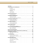
Table of Contents Overview . . . . . . . . . . . . . . . . . . . . . . . . . . . . . . . . . . . . . . . . . . . . . . . 7 Components of the Disk System . . . . . . . . . . . . . . . . . . . . . . . . . . . . . 8 Front Panel . . . . . . . . . . . . . . . . . . . . . . . . . . . . . . . . . . . . . . . . . . . . . . . . . . . . . . . . . . . . . . 8 Disk Module LEDs . . . . . . . . . . . . . . . . . . . . . . . . . . . . . . . . . . . . . . . . . . . . . . . . . . . . . . . . 8 System Power LED. . . . . . .
Table of Contents Regulatory Statements . . . . . . . . . . . . . . . . . . . . . . . . . . . . . . . . . . . 36 Safety Certifications . . . . . . . . . . . . . . . . . . . . . . . . . . . . . . . . . . . . . . . . . . . . . . . . . . . . . . 36 EMC Compliance . . . . . . . . . . . . . . . . . . . . . . . . . . . . . . . . . . . . . . . . . . . . . . . . . . . . . . . . 36 A. FCC Notice for United States . . . . . . . . . . . . . . . . . . . . . . . . . . . . . . . . . . . . . . . . . . . . 36 B.
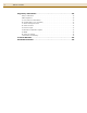
List of Figures Figure 1 Disk Module LEDs . . . . . . . . . . . . . . . . . . . . . . . . . . . . . . . . . . . . . . . . . . . . . . . . . . . . . . . . . . . 8 Figure 2 System Power LED. . . . . . . . . . . . . . . . . . . . . . . . . . . . . . . . . . . . . . . . . . . . . . . . . . . . . . . . . . . 9 Figure 3 Rear View of the Disk System . . . . . . . . . . . . . . . . . . . . . . . . . . . . . . . . . . . . . . . . . . . . . . . . . . 9 Figure 4 Power Button . . . . . . . . . . . . . . . . . .
List of Tables Table Table Table Table Table Table Table Table Table Table Table Table Table Table Table 1 2 3 4 5 6 7 8 9 10 11 12 13 14 15 Disk LED Activity Definitions. . . . . . . . . . . . . . . . . . . . . . . . . . . . . . . . . . . . . . . . . . . . . . . . . . 8 System Power LED Activity Definitions . . . . . . . . . . . . . . . . . . . . . . . . . . . . . . . . . . . . . . . . . 9 AC Power Requirements . . . . . . . . . . . . . . . . . . . . . . . . . . . . . . . . . . . . . . . . . . . . .
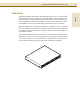
HP StorageWorks Disk System 2100 / 2110 7 Overview Both units support Ultra3 (U160) drives and the new U320 drives. However, the U320 drives are supported at a maximum of 160 MB/s speeds. The Disk System 2100 does not support the U320 73-GB drive (part number A7286A) or the U320 146-GB drive (part number A7287A). For both the DS2100 and DS2110, connectivity to U320 initiators is supported if the speed of the U320 initiator is set to limit negotiations to U160 speed.
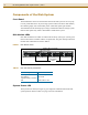
HP StorageWorks Disk System 2100 / 2110 Components of the Disk System Front Panel The disk modules can be accessed from the front of the disk system. It can accept up to 4 low profile disk drives. If your storage system contains less than 4 disk modules, the remaining empty slots contain filler panels. These filler panels (part number A6198-60002) ensure that the proper cooling is maintained within the storage system. Remove filler panels only when a disk module is added to the system.
HP StorageWorks Disk System 2100 / 2110 FIGURE 2 9 System Power LED English System Power LED TABLE 2 System Power LED Activity Definitions LED Activity Indication Blinking Malfunction - either a fan is not operating properly or internal voltage is too low. On solid Disk system is operating properly. Off Disk system is off.
HP StorageWorks Disk System 2100 / 2110 SCSI ID Switch The SCSI ID switch sets the address for the disk drives. There are three possible settings for the SCSI address switch: A, B, and C. Each setting assigns a different set of addresses to the disk modules installed in the disk system. For SCSI address switch setting A, the addresses for the installed disk modules are (from left to right, looking at the disk system from the front) 0, 2, 4, and 6.
HP StorageWorks Disk System 2100 / 2110 11 Power Connector FIGURE 6 AC Power Connector Location English AC Power Connector Electrical Requirements AC Site Requirements Overcurrent protection devices are required for each cabinet where the disk system is installed. They must be positioned between the power source and the disk system. These protective devices must not trip when exposed to an inrush current of 30 amps lasting 5 ms.
HP StorageWorks Disk System 2100 / 2110 Installing the Disk System Hardware Requirements The following hardware is included with the disk system: One power cord comes with each disk system.
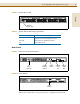
HP StorageWorks Disk System 2100 / 2110 13 Setting the SCSI IDs for the Disk Modules 1 Determine which SCSI addresses are not being used on the host system. 2 Locate the SCSI switch on the back of the disk system. FIGURE 7 SCSI Switch Location C B A SCSI Address Switch Setting A B C Disk Module SCSI Addresses (Viewed from front of storage enclosure) 6 14 15 4 12 13 2 10 11 0 8 9 3 Set the SCSI IDs. Verify that the SCSI IDs you have chosen are available.
HP StorageWorks Disk System 2100 / 2110 Keep in mind that the host bus adapter should have the highest SCSI address priority. See Table 5 below. TABLE 5 SCSI Address Priority SCSI ID 7 Priority 6 5 4 3 2 1 0 15 14 13 12 Highest 11 10 9 8 Lowest Installing the Disk System See the installation instructions enclosed with your rackmount kit. Connect the SCSI Cables 1 Make sure that the host system has been powered down.
HP StorageWorks Disk System 2100 / 2110 15 4 Determine if this disk system is at the beginning or end of the SCSI bus. – If the disk system is at the beginning or middle of the SCSI bus (you are going to daisy-chain another device off this one), consider the following: • Due to SCSI ID restrictions, no more than three of these disk systems can be daisy-chained together. • For the DS2110, use only 0.5-meter cable between enclosures in daisy-chain configurations.
HP StorageWorks Disk System 2100 / 2110 Connecting the Power Cable CAUTION FIGURE 9 Ensure that the connection of multiple units to the supply circuit does not overload the supply overcurrent protection or the supply wiring. Refer to the storage electrical ratings when determining the correct branch circuit rating for your installation. See Table 3 on page 11. AC Power Connector Location AC Power Connector Powering On and Off Power On the Disk System 1 Press the power button and release it.
HP StorageWorks Disk System 2100 / 2110 17 Power Off the Disk System 1 Back up all data if the disk system is still operational. 3 Unmount any file systems associated with the disk system that is going to be powered off. Refer to the system administration manual for your host system’s operating system for the correct procedure for unmounting a file system or stopping access to the disk modules within the disk system.
HP StorageWorks Disk System 2100 / 2110 Adding Disk Modules Disk modules can be added, removed, and replaced while the disk system is running. Because the disk modules can be handled in this way, they are called hot-pluggable. The SCSI addresses for the disks are set using the addressing switches on the back of the disk system. You can determine the assigned SCSI addresses by looking at the SCSI address switch settings at the rear of the disk system.
HP StorageWorks Disk System 2100 / 2110 19 FIGURE 11 Installing a Disk Module English Configure the new Disk Module Configure a new disk module within your application. CAUTION These procedures should be performed only by qualified system administrator. Performing hot-plug operations on an active disk drive can result in data loss or corruption.
HP StorageWorks Disk System 2100 / 2110 2 Prepare the software environment to remove the drive. See your operating system documentation for instructions and procedures required to remove a disk module. It may be necessary to unmount file systems associated with the disk drives installed in the disk system. 3 Unlatch the disk module handle and remove the disk module. Squeeze the latch to unlock the disk module.
HP StorageWorks Disk System 2100 / 2110 21 Remove the Disk System Reverse the installation instructions enclosed with the rackmount kit for your cabinet: ■ ■ ■ ■ A5679A - Hewlett-Packard Rack Systems/E for Enterprise Systems A5680A - all other Hewlett-Packard rack systems for Enterprise Systems purchased before November 1998. A6532A - Hewlett-Packard Rack Systems/E for Commercial Systems A6533A - all other Hewlett-Packard rack systems for Commercial Systems purchased before November 1998.
HP StorageWorks Disk System 2100 / 2110 Setting Up the Hardware Event Monitor (HP-UX Only) Hardware event monitors run on HP-UX hosts, versions 10.20 and later. The Disk Monitor (disk_em) monitors all disks bound to sdisk drivers. Consequently, if the Disk Monitor is active on your host, it is already set up to monitor the disks of a new disk system.
HP StorageWorks Disk System 2100 / 2110 23 Event Notification (HP-UX Only) Event severity ranges from critical to informational: Critical An event that causes data loss, host system downtime, or other loss of service. Host system operation will be affected if the disk system continues to be used without correction. Immediate action is required. For example, read data could not be recovered. Serious An event that may cause data loss, host system downtime, or other loss of service if left uncorrected.
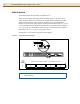
HP StorageWorks Disk System 2100 / 2110 FIGURE 13 Sample Hardware Event Notification Notification Time: Wed Feb 3 11:27:15 1999 yourserver sent Event Monitor notification information: /storage/events/disks/default/10_4_4_0.0 is >=1. Its current value is CRITICAL(5) Event data from monitor: Event Time: Wed Feb 3 11:27:15 1999 Hostname: yourserver.rose.hp.com Event ID: 0x0036b8a313000000002 Event # : 100037 Severity : CRITICAL IP Address : 15.43.213.
HP StorageWorks Disk System 2100 / 2110 25 Status LEDs FIGURE 14 LED Status Indicators Amber LED (not used) Green LED Disk Module LEDs System Power LED TABLE 6 LED Status Indicators LED State Indication System Power Green Power is on Blinking Malfunction - either a fan is not operating properly or internal voltage is too low. OFF Power is off Green Installed and spinning up.
HP StorageWorks Disk System 2100 / 2110 View Disk Status HP-UX and MPE/iX utilities provide descriptive and diagnostic information about disks, including disk type, firmware revision, and errors. On HP-UX and MPE/iX 6.5 or later, the disk utility is Support Tools Manager (STM). For all other operating systems, consult the appropriate system administration manual for disk module status checking procedures. STM Disk Information: HP-UX STM displays the last-generated Information Log for a selected disk.
HP StorageWorks Disk System 2100 / 2110 27 FIGURE 15 Sample STM Information Log (HP-UX) English
HP StorageWorks Disk System 2100 / 2110 STM Disk Information: MPE/iX 6.5 or Later STM displays the last-generated Information Log for a selected disk. Start STM and run the Information tool as follows. 1 Log on the system. 2 At the system prompt (:), type vsclose . This removes the disk from use. 3 At the system prompt (:), type cstm. STM starts. 4 At the cstm prompt, type map. STM displays a list of all the disks installed on the system.
HP StorageWorks Disk System 2100 / 2110 29 FIGURE 16 Sample STM Expert Tool Disk Error Log (MPE/iX 6.5 or Later) Write Error Statistics N/A 0 0 0 0 6.3253e+10 0 Read Error Statistics Errors Corrected Without Delay: Errors Corrected With Delay: Total Retries: Total Errors Corrected: Correction Algorithm Executions: Total Bytes Processed: Total Uncorrected Errors: 23781 0 0 23781 23781 9.
HP StorageWorks Disk System 2100 / 2110 Isolating Faults Table 7 lists the probable causes and solutions for problems you may detect on the disk system. When more than one problem describes your situation, investigate the first solution that applies. The table lists the most basic problems first and excludes them from subsequent problem descriptions.
HP StorageWorks Disk System 2100 / 2110 LED State ioscan (HPUX) lists disk as NO_HW, or Mapper or dstat all (MPE/iX) lists no device type Disk module LED is on solid or off Unable to configure device for use by operating system Disk module LED is on solid or off Probable Cause Solution Disk module is faulty. Replace the disk module. Enclosure is faulty. Replace the enclosure chassis. If the all disks on the bus have Replace the cable. this problem, the cable is faulty.
HP StorageWorks Disk System 2100 / 2110 Reference Information Product Numbers and Options TABLE 8 Product Numbers Disk System 2100 Product Number UPC Code Description A5675A (None) Field-racked disk system with at least one drive A5675AD (None) Desktop disk system with at least one drive A5675AZ (None) Factory-racked disk system with at least one drive A5675AE 0 88698-48848 5 Field-racked disk system, empty enclosure only A5675ED 0 88698-48849 2 Desktop disk system, empty enclosure o
HP StorageWorks Disk System 2100 / 2110 33 Upgrade Disk Products Available Available Upgrade Disk Modules Product Number UPC Code Description1 A6571A 8 08736-45416 2 36-GB 10,000 rpm LVD U320 disk module A7285A 8 08736-45417 9 73-GB 10,000 rpm LVD U320 disk module A7286A2 8 08736-45418 62 73-GB 15,000 rpm LVD U320 disk module A7287A2 8 08736-45419 32 146-GB 10,000 rpm LVD U320 disk module A7328A 8 08736-33052 7 18-GB 15,000 rpm LVD U320 disk module A7329A 8 08736-33053 4 36-GB 15,000 r
HP StorageWorks Disk System 2100 / 2110 TABLE 11 Replaceable Parts Product Number Description Customer Field Replaceable Replaceable Replaceable Part Numbers Unit (CRU) Unit (FRU) A5675A DS2100 Base Disk System Assembly A5675-69003 Yes Yes A6198A Disk Filler Panel A6198-67002 Yes Yes A6571A* 36-GB 10,000 rpm LVD U320 disk mod. A6571-69001 Yes Yes A7285A* 73-GB 10,000 rpm LVD U320 disk mod. A7285-69001 Yes Yes A7286A* 73-GB 15,000 rpm LVD U320 disk mod.
HP StorageWorks Disk System 2100 / 2110 35 Specifications Measure Metric English Width 45.08 cm 17.75 in Depth 38.10 cm 15.0 in Height 4.32 cm 1.7 in Weight without disk modules 4.94 kg 10.90 lbs Weight fully loaded 8.11 kg 17.
HP StorageWorks Disk System 2100 / 2110 Operating Temperatures If the storage system is installed in a multi-unit rack assembly, the operating ambient temperature of the rack environment may exceed room ambient temperature. For the Disk System 2100 the rack environment ambient temperature cannot exceed 40° Celsius (104° Fahrenheit). For the Disk System 2110 the rack environment ambient temperature cannot exceed 35° Celsius (95° Fahrenheit).
HP StorageWorks Disk System 2100 / 2110 37 radiate radio frequency energy and, if not installed and used in accordance with the instruction manual, may cause harmful interference to radio communications. B. Canadian Notice (Avis Canadien) This Class A digital apparatus meets all requirements of the Canadian InterferenceCausing Equipment Regulations. Cet appareil numérique de la classe A respecte toutes les exigences du Règlement sur le matériel brouilleur du Canada. C.
HP StorageWorks Disk System 2100 / 2110 G. BSMI H. Notice for Germany Schalldruckpegel Lp = 55.
HP StorageWorks Disk System 2100 / 2110 39 I. Declaration of Conformity According to ISO/IEC Guide 22 and EN 45014 Manufacturer's Name: Hewlett-Packard Company Manufacturer's Address: 11311 Chinden Blvd.
HP StorageWorks Disk System 2100 / 2110 Product Web Site For the most current information about the HP StorageWorks Disk System 2100, visit the support Web site located at http://www.hp.com/support/ds2100 For the most current information about the HP StorageWorks Disk System 2110, visit the support Web site located at http://www.hp.com/support/ds2110.
HP StorageWorks Disk System 2100 / 2110 41 English
HP StorageWorks Disk System 2100 / 2110