
DCFM Enterprise User Manual (53-1001775-01, June 2010)


378 DCFM Enterprise User Manual
53-1001775-01
FCIP platforms and supported features
16
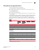
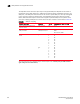
The way FCIP tunnels and virtual ports map to the physical GbE ports depends on the switch or
blade model. The 8 Gbps 16-FC ports, 6-Gbps ports extension switch and 8 Gbps 12-FC port, 10
GbE ports, 2-10 GbE ports blade tunnels are not tied to a specific GbE port, and may be assigned
to any virtual port within the allowed range. The 4 Gbps Router, Extension switch and 4 Gbps
Router, Extension blade require tunnels to be mapped to specific GbE ports and specific virtual
ports. The mapping of GbE ports to tunnels and virtual port numbers is summarized in Table 22.
The
4 Gbps Extension Switch presents only 2 active FC ports and 1 virtual port per GbE interface
(ge0 and ge1 in the table above).
TABLE 22 GbE port mapping
Switch or Blade Model GbE ports Tunnels Virtual ports (VE_Ports, VEX_Ports)
8 Gbps 16-FC ports, 6-Gbps ports
extension switch
GbE ports 0-5 0-8 16-23
8 Gbps 12-FC port, 10 GbE ports, 2-10
GbE ports blade
GbE ports 0-9
10GbE ports 10, 11
0-20 12-21 used by GbE ports (0-9) and by
XGE1
24-31 used by XGE0
4 Gbps Router, Extension switch and
blade
ge0 0
1
2
3
4
5
6
7
16
17
18
19
20
21
22
23
ge1 0
1
2
3
4
5
6
7
24
25
26
27
28
29
30
31