
DCFM Enterprise User Manual (53-1001775-01, June 2010)


DCFM Enterprise User Manual 381
53-1001775-01
Bandwidth calculation during failover
16
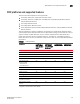
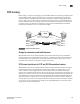
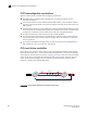
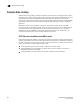
In Figure 151, circuit 1 is assigned a metric of 0, and circuit 2 is assigned a metric of 1. In this case,
circuit 2 is a standby that is not used unless there are no lowest metric circuits available. If all
lowest metric circuits fail, then the pending send traffic is retransmitted over any available circuits
with the higher metric,
FIGURE 151 Failover to a higher metric standby circuit
Bandwidth calculation during failover
The bandwidth of higher metric circuits is not calculated as available bandwidth on an FCIP tunnel
until all lowest metric circuits have failed. For example, assume the following:
• Circuits 0 and 1 are created with a metric of 0. Circuit 0 is created with a maximum
transmission rate of 1 Gbps, and Circuit 1 is created with a maximum transmission rate of 500
Mbps. Together, Circuits 0 and 1 provide an available bandwidth of 1.5 Gbps.
• Circuits 2 and 3 are created with a metric of 1. Both are created with a maximum transmission
rate of 1 Gbps, for a total of 2 Gbps. This bandwidth is held in reserve.
• If either circuit 0 or circuit 1 fails, traffic flows over the remaining circuit while the failed circuit
is being recovered. The available bandwidth is still considered to be 1.5 Gbps.
• If both circuit 0 and circuit 1 fail, there is a failover to circuits 2 and 3, and the available
bandwidth is updated as 2 Gbps.
• If a low metric circuit becomes available again, the high metric circuits go back to standby
status, and the available bandwidth is updated again. For example, if circuit 0 is recovered, the
available bandwidth is updated as 1 Gbps. If circuit 1 is also recovered, the available
bandwidth is updated as 1.5 Gbps.
7800
7800
Circuit 1 - Metric 0 - Active
Circuit 2 - Metric 1 - Standby