
DCFM Enterprise User Manual (53-1001775-01, June 2010)


DCFM Enterprise User Manual 469
53-1001775-01
Configuring a PDCM Allow/Prohibit Matrix
18
2. Select a switch from Available Switches.
Two default configurations (Active and IPL) are displayed in a tree structure below the switch.
Existing configurations are also displayed.
3. Choose one of the following options:
• Double-click a configuration file.
• Select a configuration file and click the right arrow.
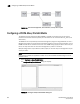
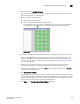
A matrix displays. The switch ports are displayed on both the vertical axis and horizontal
axis. A green circle icon ( ) indicates communication is allowed between the ports.
FIGURE 198 Active Configuration
4. Prohibit a connection between two ports by clicking the intersection point between the ports.
A prohibit icon ( ) displays at the intersection point. If you know the port addresses of the
ports for which you want to prohibit or allow communication and do not want to search the
matrix for the exact port intersection point, use the procedure “Configuring an Allow/Prohibit
manually” on page 470.
5. Repeat step 4 as needed to create the matrix you want to apply. If you want to change a
selection from prohibit to allow, click the intersection point to clear the prohibit icon.
6. When you have completed the matrix, click Save if you started with a new matrix, or Save As to
save a copy of an existing matrix.
7. Clic k Analyze Zone Conflicts.
This operation can be done before or after a configuration is saved. This operation checks the
current zoning settings for conflicts with settings in the PDCM matrix. Zone conflict is analyzed
against the switch for port zoning only. The table cells display in the red background if the two
ports are not in the same zone in an active zone configuration.
8. Click Close on the Configure Allow/Prohibit Matrix dialog box.