
DCFM Professional Plus User Manual (53-1001774-01, June 2010)


DCFM Professional Plus User Manual 375
53-1001774-01
15
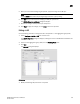
5. Configure the following CEE Map parameters in the CEE Map table:
• Name - Enter a name to identify the CEE map. If the switch is a 10 Gbps CEE/FC switch
module, you cannot change the name.
• Precedence - Enter a value between 1 - 100. This number determines the map’s priority.
• Priority Flow Control check box - Check to enable priority flow control on individual priority
groups.
• CoS - Enter a Class of Service value to correspond to the Priority Group ID rows. All of the
eight CoS values (0-7) must be used in a CEE map. Duplicate CoS values in two or more
priority groups are not allowed.
NOTE
You can only edit CoS fields that are displayed with a green tick mark.
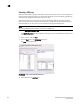
% Bandwidth (optional) - Enter a bandwidth value for priority group (PG) IDs 0-7. You must
map each CoS to at least one of the PG IDs. Use a comma or a space to separate multiple
CoS values, as shown in Figure 115.
Note the following points:
• You cannot define a bandwidth percentage for Strict Priorities (PG ID 15.0 - 15.7). The
total % Bandwidth for PG ID 15.0-15.7 must equal 0%.
• If you set a CoS value to one or more of the PG IDs 0-7, you must also enter a non-0%
bandwidth percentage. The total % Bandwidth must equal 100%.
• For PG IDs 0-7 that do not have an assigned CoS value or PFC enabled, the %
Bandwidth must be 0%.
6. Click the right arrow button to add the map to the CEE Maps table.
If a CEE map exists with the same name, a validation dialog box launches and you are asked if
you want to overwrite the map.
7. Click OK.
The CEE Confirmation and Status dialog box displays.
8. Review the changes carefully before you accept them.
9. Click Start to apply the changes, or click Close to abort the operation. If any configuration
errors exist in the CEE map, an error message displays in the Status area.