
DCFM Professional Plus User Manual (53-1001774-01, June 2010)


408 DCFM Professional Plus User Manual
53-1001774-01
16
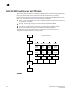
The way FCIP tunnels and virtual ports map to the physical GbE ports depends on the switch or
blade model. The 8 Gbps 16-FC ports, 6-Gbps ports extension switch and 8 Gbps 12-FC port, 10
GbE ports, 2-10 GbE ports blade tunnels are not tied to a specific GbE port, and may be assigned
to any virtual port within the allowed range. The 4 Gbps Router, Extension switch and 4 Gbps
Router, Extension blade require tunnels to be mapped to specific GbE ports and specific virtual
ports. The mapping of GbE ports to tunnels and virtual port numbers is summarized in Table 25.
The
4 Gbps Extension Switch presents only 2 active FC ports and 1 virtual port per GbE interface
(ge0 and ge1 in the table above).
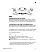
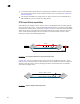
FCIP trunking
FCIP Trunking is a method for managing the use of WAN bandwidth and providing redundant paths
over the WAN to protect against transmission loss. This feature is available only on the 8 Gbps
extension switches and 8 Gbps extension blades. Trunking is enabled by creating logical circuits
within an FCIP tunnel. A tunnel may have multiple circuits. Each circuit is a connection between a
pair of IP addresses that are associated with source and destination endpoints of an FCIP tunnel,
as shown in Figure 129. Each circuit represents a portion of the available Ethernet bandwidth
provided by the GbE ports that are connected to the WAN.
TABLE 25
Switch or Blade Model GbE ports Tunnels Virtual ports (VE_Ports, VEX_Ports)
8 Gbps 16-FC ports, 6-Gbps ports
extension switch
GbE ports 0-5 0-8 16-23
8 Gbps 12-FC port, 10 GbE ports, 2-10
GbE ports blade
GbE ports 0-9
10GbE ports 10, 11
0-20 12-21 used by GbE ports (0-9) and by
XGE1
24-31 used by XGE0
4 Gbps Router, Extension switch and
blade
ge0 0
1
2
3
4
5
6
7
16
17
18
19
20
21
22
23
ge1 0
1
2
3
4
5
6
7
24
25
26
27
28
29
30
31